-
Paper Information
- Next Paper
- Paper Submission
-
Journal Information
- About This Journal
- Editorial Board
- Current Issue
- Archive
- Author Guidelines
- Contact Us
Journal of Mechanical Engineering and Automation
p-ISSN: 2163-2405 e-ISSN: 2163-2413
2016; 6(3): 43-50
doi:10.5923/j.jmea.20160603.01

The Forming Analysis of Two-stage Extrusion for 1010 Fastener
 Abstract
 Reference
 Full-Text PDF
 Full-text HTML
Chih-Cheng Yang, Xuan-Yu Lin
Department of Mechanical and Automation Engineering, Kao Yuan University, Taiwan
Correspondence to: Chih-Cheng Yang, Department of Mechanical and Automation Engineering, Kao Yuan University, Taiwan.
| Email: |  |
Copyright © 2016 Scientific & Academic Publishing. All Rights Reserved.
This work is licensed under the Creative Commons Attribution International License (CC BY).
http://creativecommons.org/licenses/by/4.0/

Cold extrusion forming is usually applied in forging for fastener. In this study, two forming modes of two-stage extrusion forming are studied numerically and experimentally with carbon steel AISI 1010. The forming mode 1 is to extrude a billet into one-stage rod and to upset a head, and the forming mode 2 is to extrude a billet into two-stage rod. The forming experiments are conducted on a 20 tonne universal testing machine with a two-stage extrusion forming die. The numerical analysis of extrusion forming is studied by using FE code of DEFORM-3D. The formability of both forming modes is investigated. It is revealed experimentally and numerically that, for forming mode 1, the forging load increases rapidly as upsetting the head compactly, the maximum load is even larger than forming mode 2. Increasing forging load to achieve complete metal forming into the die filling of head may cause die wear and fracture. However, for the deformation energy, it is only about one third of forming mode 2. For forming mode 2, the forging load of the second extrusion is about twice larger than the first extrusion due to the strain hardening effect. The effective strains in extrusion and upsetting regions of workpiece were higher than the middle region for forming mode 1. For forming mode 2, the effective strains are high in the region of the first extrusion forming, and higher in the region of the second extrusion forming. These effective strain distributions agree with the hardness distributions tested in experiment. Therefore, the strength of workpiece for forming mode 2 is larger than that for forming mode 1.
Keywords: Two-stage extrusion forming, Forging load, Deformation energy, Effective strain
Cite this paper: Chih-Cheng Yang, Xuan-Yu Lin, The Forming Analysis of Two-stage Extrusion for 1010 Fastener, Journal of Mechanical Engineering and Automation, Vol. 6 No. 3, 2016, pp. 43-50. doi: 10.5923/j.jmea.20160603.01.
Article Outline
1. Introduction
- Cold extrusion forming is usually applied in forging for fastener. Cold forging is performed at room temperature and is used to achieve better tolerance, higher mechanical properties, and a better surface aspect that can avoid further machining (Wagoner and Chenot, 2001). In cold extrusion, the tool stresses are quite high. Therefore, the prediction of the forming load and stresses is very important for die design and machine selection. In addition, the distribution of the strains in each deformation stages is significant, since it determines the hardness distribution as well as the formability of the part (Kobayashi et al., 1989). Both strains and stresses are influenced by area reduction, die geometry, extrusion velocity, lubrication, workpiece material, and billet dimensions. The processes of cold extrusion involve forming a billet placed in a die, most commonly for the production of discrete parts. The basic processes involved in cold extrusion are classified depending on their forming direction as forward, backward and lateral extrusion and also according to the final form of workpiece as rod, tube and cup extrusion (SCHULER Group, 1998).Maccarini et al. (1991) investigate the influence of die geometry on cold extrusion forging. The friction phenomenon and the shape of the dies play a fundamental role in determining the plastic flow of the material in the dies. In particular the study concerns the results obtained when the fillet radius of the die was varied and then tested in a process of extrusion forging. The rake angle of the extrusion hole provides a solution similar to the devices actually in use. Cold forging involves typically several pre-forming operations and fracture is often a limiting factor due to severe deformation during cold forging. Oh et al. (1992) discuss the features required to simulate cold forging operations and present example solutions to demonstrate the capabilities of the DEFORM system. Reddy et al. (1995) propose an upper-bound model with strain hardening to predict the extrusion power, which is as accurate as that determined by the finite-element method and is in excellent agreement with experimental results. When combined with the slab method, the upper-bound model also predicts the die pressure distribution, which is in reasonable agreement with FEM results. The proposed combined upper-bound/slab method is applied to compare eight different die shapes, namely, stream-lined, elliptical, hyperbolic, conical and Blazynski's CRHS. Based on the consideration of total extrusion power, it is concluded that third- and fourth-order polynomial dies and the cosine die are the best amongst the profiles considered.Joun et al. (1998) present a computer simulation technique for the forging process having a spring-attached die. A penalty rigid-viscoplastic finite element method is employed together with an iterative force-balancing method, in which convergence is achieved when the forming load and the spring reaction force are in equilibrium within the user-specified allowable accuracy. The significance of metal flow lines for quality control and the effects of spring-attached dies on the metal flow lines as well as the decrease in forming load are investigated. Wu and Hsu (2002) use the finite element method to analyze the influence of die shapes with different draft angles and fillet radii on the extrusion forging deformation. Two sets of dies with different shapes are performed, and the results are compared with the predictions of the finite element method for the same deformation mode. Cho et al. (2003) study the process design of a forward and backward extruded axi-symmetric part with the commercial finite element code, DEFORM. It was found that the shape of the pre-form with 12.5 mm of lower extrusion was favorable. The optimum process for the final product was that final forming has to be carried out with an annealed pre-form.Farhoumand and Ebrahimi (2009) present the analysis of forward–backward-radial extrusion process with the finite element code, ABAQUS, to investigate the effect of geometrical parameters such as die corner radius and gap height as well as process condition such as friction on the process. The finite element results are compared with experimental data in terms of forming load and material flow in different regions. Hardness distribution in longitudinal cross-section of the product is used to verify strain distribution obtained from finite element analysis. Jafarzadeh et al. (2012) study the lateral extrusion process with the FE code of DEFORM-3D to analyze the effects of some important geometrical parameters such as initial billet dimensions, gap height and frictional condition on the required forging load, the material flow pattern and effective plastic strain distribution. A series of experimental tests on commercial lead billets were carried out to verify the FE results. The results revealed that the gap height has the greatest effect on the forming load and material flow.There are many experimental and numerical studies in extrusion forming. This study presents the analysis of two-stage extrusion forming in one die with two distinct forming modes. The forming mode 1 is to extrude a billet into one-stage rod and then upsetting a head. The forming mode 2 is to extrude a billet into two-stage rod. The extrusion forming experiment is conducted on a 20 tonne universal testing machine with a two-stage extrusion forming die. The numerical analysis of extrusion forming is studied by using FE code of DEFORM-3D. The formability of both forming modes is investigated.
2. Two-stage Extrusion Forming
- Two-stage extrusion forming result involves a head and two-step rod, as shown in Fig. 1. There are two forming modes, as shown in Fig. 2, forming mode 1 is to extrude a billet into one-stage rod and then upsetting a head; and forming mode 2 is to extrude a billet into two-stage rod. The dimension of initial billet for forming mode 1 is
 7.72mm×L32.2mm which diameter approaches to the diameter of the first-stage rod, as shown in Fig. 2(a), and the forging stroke, ΔL = 12mm. The dimension of initial billet for forming mode 2 is
  9.76mm×L22.7mm which diameter approaches to the diameter of head, as shown in Fig. 2(b), and the forging stroke, ΔL = 20mm. Fig. 2(c) shows the geometry and dimension of extrusion die cavity.Numerical simulation of two-stage extrusion forming is modeled as three dimension finite element analysis using the code of DEFORM 3D (Fluhrer, 2003). The workpiece is modeled using tetrahedral elements. Since the tool material is typically much harder than the workpiece material, its deformation is neglected and was considered as a rigid object. The workpiece material is solid commercial carbon steel AISI 1010 billet and was considered as a rigid-plastic material with Von Misses yield criterion, isotropic hardening. The constant shear friction is considered between the workpiece and tools, and friction coefficient was m = 0.12.For extrusion experiment, commercial carbon steel AISI 1010 was used as initial workpiece material. The cylindrical billets with dimensions
  7.72mm×L32.2mm and
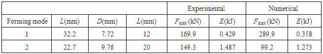
  9.76mm×L22.7mm are respectively for forming mode 1 and forming mode 2.The forming test was conducted on a 20 tonne universal testing machine under a constant ram speed of 2 mm/min at room temperature. The forging strokes are ΔL = 12mm for forming mode 1, and ΔL = 20mm for forming mode 2, respectively. Fig. 3 shows the two-stage extrusion die, punch and die block. The final lengths of workpieces for both forming modes were about 32 mm. The cross-section reduction ratio are r1 = 34.7% for the first extrusion and r2 = 32.6% for the second extrusion, respectively. The deformation energy is
 | (1) |
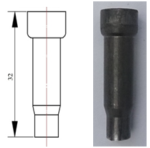 | Figure 1. Two-stage forming fastener |
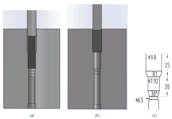 | Figure 2. The schematic illustration of extrusion forming: (a) forming mode 1; (b) forming mode 2; (c) geometry and dimension of die cavity |
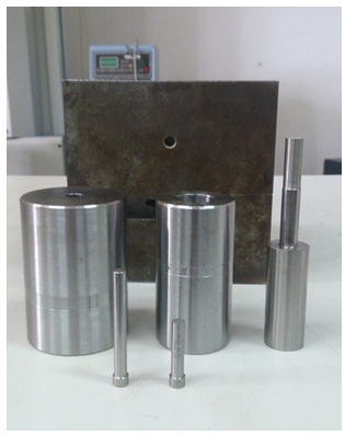 | Figure 3. Two-stage extrusion die, punch and die block |
3. Results and Discussion
- In this section, for two forming modes of two-stage extrusion forming, the effect on progressive forging load, maximum forging load, effective strain distribution and strength will be studied numerically and experimentally.
3.1. The Forging Load and Deformation Energy
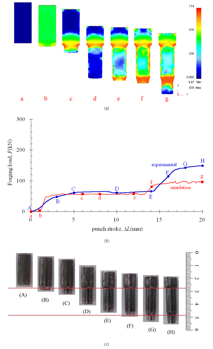
- The numerical and experimental results were obtained for forging load versus punch stroke as shown in Fig. 4 for forming mode 1 and Fig. 5 for forming mode 2, respectively. In the Figs., (a) illustrate numerical simulation of extrusion procedure and effective stress responses; (b) present numerical and experimental forging load-punch stroke curves; and (c) illustrate experimental extrusion procedure. The maximum forging load and deformation energy were listed in Table 1.For forming mode 1, as shown in Fig. 4(b), the experimental and numerical results are close. The difference between experimental and numerical results may be due to the possible measurement errors and modeling assumptions such as, neglecting the variation of friction factor, elastic deformation of the die and workpiece in practice, etc. As related to forming procedure, presented in Fig. 4(a) and 4(c) respectively for numerical simulation and experimental test, the load curves have two regions, namely, the extrusion and the upsetting. As the punch moving down, extrusion formation occurs until the front end of billet touches the knock pin (A-D for experiment and a-c for numerical in Fig. 4). As the punch stroke increasing, upsetting formation begins and continues until the diameter reaches to 9.8 mm (E-H and d-e in Fig. 4), and the forging loads increase rapidly with the increasing stroke because of the die filling of head. The maximum forging load is Fmax = 289.9 kN numerically, while Fmax = 169.9 kN experimentally (Table 1). Increasing forging load to achieve complete metal forming into the die filling of head may cause die wear and fracture. However, the deformation energy is E = 0.358 kJ numerically which is less than the experimental result, E = 0.429 kJ (Table 1) because most of the numerical forging loads were smaller than the experimental loads, as seen from Fig. 4(b). As illustrated in Fig. 4(a), the effective stress is small in the middle region of workpiece. However, the stress responses are obviously large in extrusion and upsetting regions of workpiece, especially in head region. The maximum effective stress is 678 MPa.As illustrated in Fig. 5(b), the experimental and numerical results for forming mode 2 are close, too. As related to forming procedure, presented in Fig. 5(a) and 5(c) respectively for numerical simulation and experimental test, the load curves have also two regions, namely, the first and second extrusions. As the punch moving down, the first extrusion formation occurs until the front end of billet reaches to the second extrusion die cavity (A-E for experiment and a-e for numerical in Fig. 5). In this region, the numerical forging load is relative close to the experimental forging load, as presented in Fig. 5(b). As the punch stroke increasing, the second extrusion formation begins and continues until the forging stroke reaches to 20 mm (F-H and f-g in Fig. 5), and the forging loads increase with the increasing stroke because of the strain hardening effect. The maximum forging load, as listed in Table 1, is Fmax = 99.2 kN numerically, while Fmax = 149.3 kN experimentally. However, the deformation energy is E = 1.273 kJ numerically which is less than the experimental result, E = 1.487 kJ (Table 1) because, as seen from Fig. 5(b), for the second extrusion forming, the numerical forging loads were smaller than the experimental loads. This situation is explained as a consequence of modeling assumption for strain hardening. As seen from Fig. 5(a), except the region of free end of workpiece, the stress response is evidently in overall workpiece, surely in the region of second extrusion forming. The maximum effective stress is 678 MPa, the same with forming mode 1.
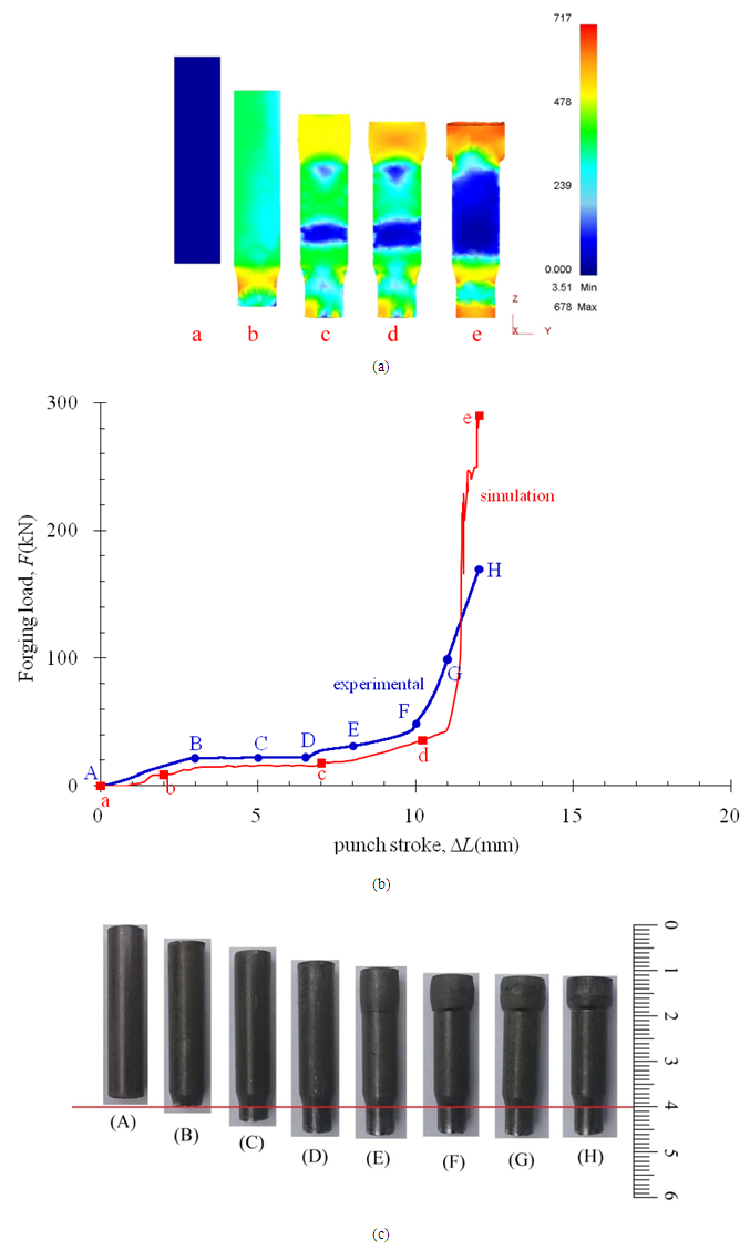 | Figure 4. (a) Numerical simulation of extrusion procedure; (b) forging load vs. punch stroke; (c) experimental extrusion procedure for forming mode 1 ( 7.72mm×L32.2mm, ΔL = 12mm) 7.72mm×L32.2mm, ΔL = 12mm) |
 | Figure 5. (a) Numerical simulation of extrusion procedure; (b) forging load vs. punch stroke; (c) experimental extrusion procedure for forming mode 2 ( 9.76mm×L22.7mm,ΔL = 20mm) 9.76mm×L22.7mm,ΔL = 20mm) |
|
3.2. The Effective Strain and Hardness
- Figs. 6(a)-(b) show the effective strain distribution for forming mode 1 and forming mode 2, respectively, which were obtained from three dimensional simulations. It is obvious that the forming mode affects the flowing of materials. For forming mode 1, the effective strains in extrusion and upsetting regions of workpiece were higher than the middle region, as illustrated in Fig. 6(a), because, in the middle region, the diameter of initial billet is very close to the diameter of die cavity, as shown in Fig. 2(a), and the deformation is so very small. For forming mode 2, as illustrated in Fig. 6(b), the effective strains are high in the region of the first extrusion forming. The region with higher effective strains increases along the die cavity because of the friction resistance on the contact surfaces between die and billet, the material flow along the cavity is not uniform. The effective strains in the front end region are very small because of free end.With cold extrusion forming, the hardness, tensile strength and yield strength of workpiece are increased by plastic flow. Fig. 7 illustrates the average hardness in cross-sections of workpieces for both forming modes, which obtained from Vickers hardness tests. The hardness of initial billets for both forming modes is almost the same (181 HV and 184 HV in Fig. 7). For forming mode 1, the hardness in extrusion and upsetting regions of workpiece (1-3 and 7-8 in Fig. 7) is larger than middle region, which agrees with the effective strain distribution as seen from Fig 6(a). The hardness over all the workpiece (216.6 HV in average) is larger than the initial billet, which increases by up to 20%. The maximum hardness is 245.6 HV, which is observed in the top section of workpiece due to upset forging.
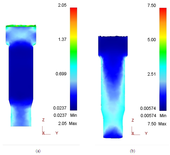 | Figure 6. Effective strain distribution for (a) extrusion forming mode 1; (b) extrusion forming mode 2 |
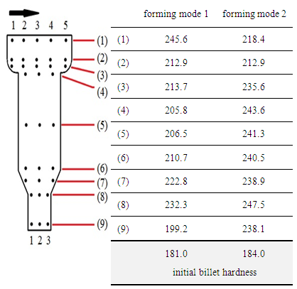 | Figure 7. Hardness in workpieces (average in HV) |
4. Conclusions
- In this paper, two forming modes of two-stage extrusion forming are studied numerically and experimentally with carbon steel AISI 1010. Forming mode 1 is to extrude a billet into one-stage rod and then upsetting a head; and forming mode 2 is to extrude a billet into two-stage rod. The extrusion forming experiment is conducted on a 20 tonne universal testing machine with a two-stage extrusion forming die. The numerical analysis of extrusion forming has been carried out by using FE code of DEFORM-3D. The formability of both forming modes is investigated, such as the effect on progressive forging load, maximum forging load, effective strain distribution and strength.The upsetting load in die cavity is much larger than the extrusion load for forming mode 1. For forming mode 2, both the extrusion loads are larger than the extrusion load for forming mode 1, but still smaller than the upsetting load in die cavity. The maximum forging load for forming mode 1 is larger than that for forming mode 2 due to upset forming. Increasing forging load to achieve complete metal forming into the die filling of head may cause die wear and fracture. While, the deformation energy for forming mode 1 is less than that for firming mode 2.The effective strains in extrusion and upsetting regions of workpiece were higher than the middle region for forming mode 1. For forming mode 2, the effective strains are high in the region of the first extrusion forming, and higher in the region of the second extrusion forming. These effective strain distributions agree with the hardness distributions tested in experiment. The hardness of workpiece for forming mode 1 increases by up to 20%, while increases by up to 28% for forming mode 2. Therefore, the strength of workpiece for forming mode 2 is larger than that for forming mode 1. This effect can be used to replace high-alloy steels by low-alloy grades if no heat treatment is carried out.
ACKNOWLEDGMENTS
- The authors are grateful to the Ministry of Science and Technology of the Republic of China (Taiwan, R.O.C.) for their support of this research under grant MOST 104-2632-E-244-001, also would like to acknowledge the support of HO HONG WORKS CO., LTD. for providing the materials to carry out the forming experimental work.