-
Paper Information
- Previous Paper
- Paper Submission
-
Journal Information
- About This Journal
- Editorial Board
- Current Issue
- Archive
- Author Guidelines
- Contact Us
Journal of Mechanical Engineering and Automation
p-ISSN: 2163-2405 e-ISSN: 2163-2413
2016; 6(2): 30-35
doi:10.5923/j.jmea.20160602.02

Ultrasonic Atomization by Difference between Vibration Displacements of Two Circular Vibrating Plates
 Abstract
 Reference
 Full-Text PDF
 Full-text HTML
Takuya Asami , Ryo Yakou , Takashi Ono , Hikaru Miura
College of Science & Technology, Nihon University, Japan
Correspondence to: Takuya Asami , College of Science & Technology, Nihon University, Japan.
| Email: |  |
Copyright © 2016 Scientific & Academic Publishing. All Rights Reserved.
This work is licensed under the Creative Commons Attribution International License (CC BY).
http://creativecommons.org/licenses/by/4.0/

One method of atomizing liquids is using ultrasound. A characteristic feature of this method is that the median value of the particle size of the atomized liquid is determined by the frequency of the ultrasonic vibrations. This feature means that the particle size can be controlled by using multiple vibration sources with different drive frequencies. However, since regular vibration sources have a single resonant frequency, the particle size is fixed. The authors therefore investigate a new method for controlling the particle size of the atomized liquid that does not depend on the resonant frequency of the vibration source. Specifically, we use the difference in magnitude between the vibration displacements of two vibrating plates to perform atomization using a vibration source consisting of two transverse vibrating plates and supplying water into the gap between these two vibrating plates. Our aim is controlling the atomized particle size, which is conventionally determined by the drive frequency, using the difference in magnitude between the vibration displacements of the two vibrating plates. In this manuscript, we first clarify how water can be atomized using two transverse vibrating plates. Next, we investigate the optimal vibrating plate shape for atomization.
Keywords: Ultrasound, Transverse vibrating plate, Atomization, Liquid
Cite this paper: Takuya Asami , Ryo Yakou , Takashi Ono , Hikaru Miura , Ultrasonic Atomization by Difference between Vibration Displacements of Two Circular Vibrating Plates, Journal of Mechanical Engineering and Automation, Vol. 6 No. 2, 2016, pp. 30-35. doi: 10.5923/j.jmea.20160602.02.
Article Outline
1. Introduction
- Liquids are atomized in a wide variety of applications, from personal products such as humidifiers, insect repellent sprays, and portable heaters to spray drying of foodstuffs, fertilizers, and paints [1-3]. Ultrasound has various usages, and is one method of atomization [4-10]. In this method, liquid is supplied to a source that is vibrating ultrasonically (20,000 times or more per second), causing the strong vibration of the liquid surface. This is advantageous over atomization by heating in that the nature of the liquid is not changed due to heat gain or loss [11]. This method also requires less energy, and because the vibrational frequency determines the median value of the particle size of the atomized liquid, the particle size can be controlled easily using multiple vibration sources with different resonant frequencies [12, 13]. However, since vibration sources generally have a single resonant frequency, the particle size is fixed and is difficult to control.The authors have therefore been investigating a method for controlling the particle size of atomized liquids that does not depend on the resonant frequency of the vibration source. Specifically, the new method employs differences in magnitude between the vibration displacements of two vibrating plates to perform atomization using a vibration source consisting of two transverse vibrating plates and supplying water into the gap between them. This should allow controlling the atomized particle size, which is conventionally determined by the drive frequency using the difference in magnitude between the vibration displacements of the two vibrating plates. In principle, a gap appears at the edges of the vibrating plates due to the difference in magnitude of the vibration displacements. Water enters this gap, and the vibrations apply pressure to the water. A liquid film of water is created by this pressure, and the edge of this liquid film becomes atomized. The pressure can be changed by changing the difference in magnitude between the vibration displacements, which changes the thickness of the liquid film and thus the particle size.In this manuscript, we first show that water can be atomized by the difference in vibration displacement between two vibrating plates using a vibration source consisting of two transverse vibrating plates that have a resonant frequency of around 20 kHz. We then investigate the optimal shape of the vibrating plates for atomization.
2. Ultrasonic Vibration Source
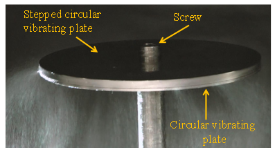
- Figure 1 shows the ultrasonic vibration source consisting of two transverse vibrating plates. It consists of a 20-kHz bolt-clamped Langevin transducer for generating longitudinal vibrations to which are attached an exponential horn (large-end diameter: 55 mm; small-end diameter: 12 mm; amplification factor: 4.6; material: duralumin) for amplifying the longitudinal vibrations and a uniform rod (length: 82 mm; diameter: 12 mm; material: duralumin) for propagating the vibrations to the vibrating plates [14-17]. Two circular transverse vibrating plates (diameter: 95 mm; material: duralumin) for converting the longitudinal vibrations into transverse vibrations and performing the atomization are attached to the tip of the rod. The ultrasonic vibration source has a total length of 1.5 times the wavelength of the longitudinal vibrations. Note that the dimensions of each part of the ultrasonic vibration source are designed such that the resonant frequency of the ultrasonic vibration source is around 20 kHz.
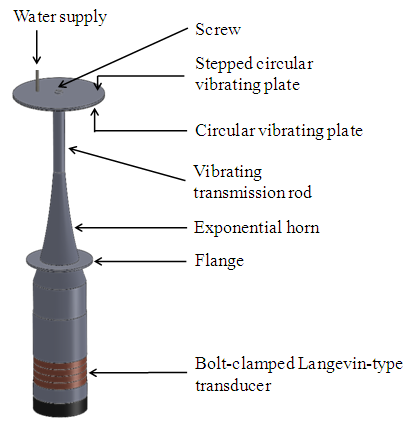 | Figure 1. Schematic drawing of ultrasonic vibration source |
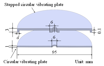 | Figure 2. Sectional view of the vibrating plates |
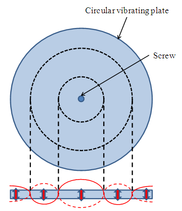 | Figure 3. Schematic of circular vibrating plate vibrations |
3. Vibration Characteristics of Vibration Source
- We investigated the vibration characteristics of the vibration source before performing the atomization experiments to ensure that the ultrasonic vibration source had the desired vibration characteristics. This investigation examined the resonant frequency of the vibration source and the vibrations produced by the two vibrating plates when the width d of the annular part was changed. When performing the atomization experiments, the width d of the annular section was varied to investigate the optimal dimension d for applying pressure to the water.
3.1. Resonant Frequency of the Vibration Source
- We measured the admittance loop of the vibration source to determine the resonant frequency and admittance properties of the vibration source. The measurements were performed by taking a drive voltage of 1 Vrms and varying the drive frequency through a range of ±1 kHz centered on the 20 kHz resonant frequency of the transducer. The measurements were performed by varying the width d of the annular section in the range of 0.5 to 5.0 mm.Figure 4 shows the admittance loop for d = 1.0 mm as an example of the results. In that figure, the vertical axis and horizontal axis show the susceptance and conductance. The figure shows that the resonant frequency of the vibration source is 19.5 kHz. The conductance at this time was approximately 30 mS. From this, it is clear that the vibration source has a single resonant frequency within the measurement range of this experiment. Furthermore, since this resonant frequency is close to the resonant frequency of the transducer alone, it is thought that the power of the transducer can be sufficiently propagated. Furthermore, since the value of conductance is around 30 mS, it is clear that the vibration source exhibits low loss.
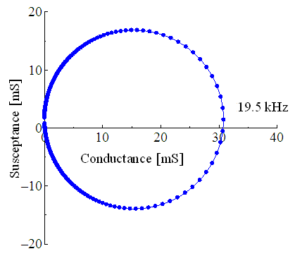 | Figure 4. Admittance loop |
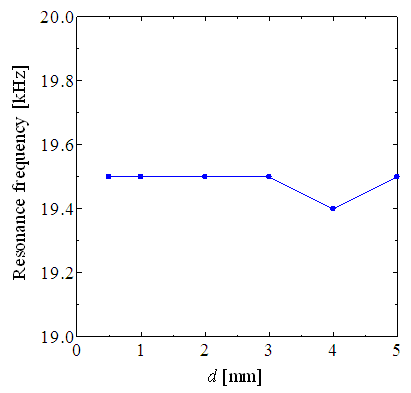 | Figure 5. Relationship between d and resonance frequency |
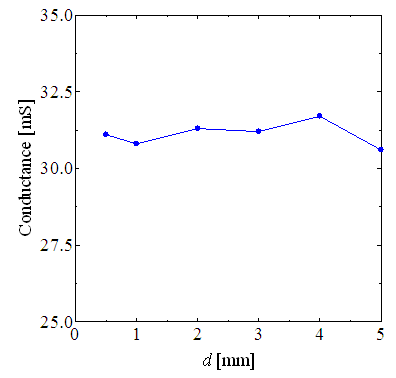 | Figure 6. Relationship between d and conductance |
3.2. Vibration Distribution of each Circular Vibration Plate
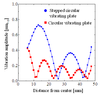
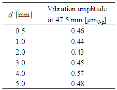
- To clarify that there is a difference in vibration displacement between the edges of each of the vibrating plates, we measured the vibration distributions of each of the vibrating plates. Measurements were performed by driving at the resonant frequencies determined above at a supply power of 0.1 W. Measurement of the vibration distribution was performed in the radial direction from the center to the edge of the circular vibrating plates using a laser Doppler vibrometer. The measurement range was the radius because the circular vibrating plates are symmetric about the center. The width d of the annular section was varied in the range of 0.5 to 5.0 mm.Figure 7 shows the vibration distribution for the case of d = 1.0 mm as an example of the results. In the figure, the vertical axis and horizontal axis show the half amplitude of the vibration displacement and the distance from the center of the circular vibrating plate. From the figure, the vibration distribution on the stepped circular vibrating plate takes maxima at distances of 14, 24, and 47.5 mm from the center, and minima at 26 and 42 mm from the center. This shows that the stepped circular vibrating plate has two nodal circular vibration modes. In the vibration distribution for the circular vibrating plate, there are maxima at distances of 6, 18, 29, 40, and 47.5 mm from the center, and minima at 11, 23, 35, and 45 mm, showing that there are four nodal circle vibration modes. This shows that the maximum values of vibration displacement in both circular vibrating plates are larger in the stepped circular vibrating plate. Furthermore, it also shows that the amplitude at the edge of the stepped circular vibrating plate is approximately twice that of the amplitude at the edge of the circular vibrating plate. This shows that a difference in vibration displacement is obtained at the edges of the vibrating plates, as designed.
 | Figure 7. Vibration distributions |
|
4. Atomization Experiments
- We performed water atomization experiments using an ultrasonic vibration source consisting of two circular vibrating plates. The experiments were performed with the gap between the vibrating plates pre-filled with water and by applying a resonant frequency at a voltage of 15 Vrms to the vibration source. We investigated whether this resulted in atomization. Figure 8 shows the state of water atomization when using a stepped circular vibrating plate with d = 1.0 mm as an example. The broad white area under the circular vibrating plate is atomized water. This shows that that water can be atomized using a vibration source consisting of two circular vibrating plates.
 | Figure 8. State of water atomization |
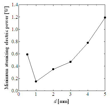 | Figure 9. Minimum atomizing electric power |
5. Summary
- We performed a basic investigation into an atomization method using the difference in vibration displacement between two vibrating plates as a new atomization method using ultrasound. As a result, we clarified that a difference in vibration displacement at the edges of vibrating plates can be produced using different values of thickness for the vibrating plates in a vibration source consisting of two circular vibrating plates. Furthermore, the vibration characteristics of the vibration source were virtually unchanged with varying values of d for the stepped circular vibrating plate, the part that applies pressure to the water. Finally, we performed atomization experiments that showed that atomization can be performed by a vibration source consisting of two circular vibrating plates and found the optimal shape of the stepped circular vibrating plate.In the future, we intend to perform a detailed investigation of atomized particle sizes and particle size control using the magnitude of the difference in vibration displacement.