Yousef Alhouli, Abdullah Alkhaledi, Abdulaziz Alzayedi, Mohsen Alardhi, Nawaf Alhaifi
Automotive and Marine Engineering Technology Dept. / Collage of Technological Studies, Public Authority of Applied Education and Training (PAAET), Kuwait
Correspondence to: Yousef Alhouli, Automotive and Marine Engineering Technology Dept. / Collage of Technological Studies, Public Authority of Applied Education and Training (PAAET), Kuwait.
| Email: |  |
Copyright © 2016 Scientific & Academic Publishing. All Rights Reserved.
This work is licensed under the Creative Commons Attribution International License (CC BY).
http://creativecommons.org/licenses/by/4.0/

Abstract
In this paper a time-frequency analysis method will beapplied with respect to engine vibration signal processing; this is the Continuous Wavelet Transform (CWT), CWT is used to divide a continuous-time function into wavelets, the continuous wavelet transform possesses the ability to construct a time-frequency representation of a signal that offers very good time and frequency localization. The mathematical characteristics of the (CWT) techniques is explained and the (CWT) method is applied to engine vibration signals under different loads, also the cylinder#1 exhaust valve clearance variations is considered in this paper. The analysis and results of the (CWT) are presented based on faults and engine vibration signals.
Keywords:
Diesel Engine, Vibration, Continuous Wavelet Transform, Condition Monitoring, Combustion
Cite this paper: Yousef Alhouli, Abdullah Alkhaledi, Abdulaziz Alzayedi, Mohsen Alardhi, Nawaf Alhaifi, Continuous Wavelet Transform on Diesel Engine Vibration Condition Monitoring, Journal of Mechanical Engineering and Automation, Vol. 6 No. 1, 2016, pp. 18-24. doi: 10.5923/j.jmea.20160601.03.
1. Introduction
Time-frequency analysis is a novel signal processing method making it possible to see both the time and frequency information in the same time. It displays the combined results from the time and frequency analysis in a three-dimensional way which plots the amplitudes against the time and frequency axes.For the applications of engine vibration analysis the time-frequency method is very useful in that most engine vibration related events such as combustion and valve operations have fixed occurring times determined by the crank mechanism. By performing time-frequency analysis these events can be identified according to their occurrence time and frequency locations [1].The most commonly used techniques are the Wavelet transform and the Winger-Ville distribution. They are superior to the conventional Fourier based frequency analysis by giving better time and frequency resolutions and locations. In the frequency analysis, the temporal information is obscured. To overcome this problem short time windows for the frequency analysis are used; but the main drawback here is that it is not possible to obtain high resolution in time and frequency simultaneously. Wavelet analysis overcomes this limitation and is very useful for analyzing non stationary signals such as those from reciprocating machinery. The beginning of the wavelet transform was in analyzing seismic signals for modeling by using a combination of translation and dilations of simple, oscillatory function of finite duration called a wavelet. The early results were related to what is now known as the continuous wavelets transform (CWT). However, wavelets expressions can be found in earlier work done in several fields such as function representation, quantum mechanics and signal processing [1].
2. Literature Review
The development of microprocessors and associated software has totally changed diesel engine condition monitoring. Condition monitoring of diesel engines used in ships has high priority because failure of the engine might result in loss of the vessel. Different faults within the engine and associated driven machinery are normally associated with the increase in the level of vibration. Such faults include abnormal combustion which is due to faulty valve or abnormal injection, wear or partial seizure of plain bearings, defects in engine mountings or drive line, damage to gear teeth, wear and pitting of rolling bearings, damage or fouling of turbocharger, etc. This paper concentrates only on combustion related faults such as change exhaust valve clearance.Vibration accelerometer may be mounted at strategic locations on the engine. In this paper, the accelerometer is located between cylinder #1 and cylinder #2 to sense abnormal combustion. However the analysis of vibration signals is not an easy task particularly with machines such as diesel engines which may have high level of background vibration [2]. In reference [3] Haddad et al. analyzed and calculated the piston slap considering all the possible piston position using engine block vibration. Nurhadi et al. [4] have studied the correlation between the vibrations measured by accelerometers mounted on an engine block with engine components as the sources for the excitations. In their experiment the engine was motored by an electric motor through a v-belt, while compression and combustion were alleviated by moving the spark plug. They concluded that sources of vibrations such as gear pair, chain-sprocket, gudgeon pin and abnormal application could be identified by the application of vibration signature analysis. Gu et al. [5] demonstrated that common injector faults change the vibration energy of the injection pulses and on this basis the monitoring of the injector via the comparison of monitored pulses with a baseline is described. Thomas et al. [6] have also used a pattern recognition technique to detect engine knock based on the vibration signal. Debotton et al. [7] have applied the vibration signature analysis method to determine the condition status of an internal combustion engine. They used accelerometer which is mounted on an operating spark ignition engine. Also they used FFT analyzer to transform the measurements from the time domain to the frequency domain, and the characteristics are analyzed during normal and abnormal operation conditions. Grimmelius and Meiler [8] have developed a feature extraction and pattern recognition algorithm to detect cylinder miss-fire in a diesel engine by applying a base-level signal analysis and torsion peak value analysis on crankshaft torsional signal. Teraguchi et al. [9] investigated the effect of oil film between piston rings and cylinder walls on the induced vibrations. Alhussain et al. [10] extracted useful information about the diesel engine lubricating oil quality and condition by analyzing the measured vibration and airborne acoustic signals caused by piston slap and investigated the effects of load, speed variation and temperatures. They found that the peaks on the frequency range between 1 kHz and 3 kHz associated with the oil level and quality, in other words the piston slap excitation. Alhussain et al. [11] outlined the diesel engine acoustic sources and their fundamental characteristics are studied in time domain, frequency domain, mean value, kurtosis, and RMS values. Also they detected and diagnosed exhaust valve clearance fault by monitoring the spikeness level using the RMS values of the acoustic signals kurtosis for each cylinder. This research study focuses on vibration monitoring techniques and characteristics of the diesel engine to detect and diagnose some combustion related faults in diesel engine. In this research vibration data collected from a Ford FSD diesel engine are used for the detection and diagnosis of specific incipient engine related faults. The real data will be collected from the engine test rig operating under normal and abnormal conditions. In the abnormal condition the fault in the engine will be on cylinder #1 change exhaust valve clearance. The vibration signals will be processed using conventional vibration signal processing techniques namely, time domain (waveforms comparison, RMS value, kurtosis and skweness) and spectral analysis techniques using Fast Fourier Transform under different operating conditions (loads and speeds). Also using some advanced techniques such as: time-frequency domain analysis using wavelets.
3. Definition of the Continuous Wavelet Transform (CWT)
If the function f (t) is square integrable, its CWT with respect to a wavelet Ψ (t) is defined as: | (1) |
Where (a) is dilation factor, (b) is the translation factor and Ψ (t) is the mother wavelet or analyzing wavelet. The factor  is used for energy normalisation.The wavelet transform is a function of two variables. Observe that both f (t) and Ψ (t) belong to
  the set of square integrable functions, also called the set of energy signals. Equation (1) can be written in a more compact form by defining
  .
. | (2) |
By combining the equations (1) and (2) we get: | (3) |
Where The normalising factor of
  ensures that the energy stays the same for all a and b, that is:
 | (4) |
For all a and b. For any given value of a, the function  is a shift of
  by an amount b along the time axis. Thus, the variable b represents time shift or translation. From equation (5).
 | (5) |
It follows that  is a time-scaled and amplitude-scaled version of
  . Since (a) determines the amount of time scaling of dilation, it is referred to as the scale or dilation variable. If a >1, there is a contraction of
  along the time axis, whereas if 0< a <1, there is a contraction of
  . Since the CWT is generated using dilates and translates of the signal function
  , the wavelet for the transform is referred to as the mother wavelet [1]. Continuous wavelet transform has got some properties which make it better than other time-frequency techniques in analysing such impulsive signals like diesel engine vibration signals. These properties are higher resolution and better localization characteristics. Also compared with the discrete wavelet transform (DWT), (CWT) is better for signal detection and feature extraction [12]. Also (CWT) has been reported to give a non-linear representation of the frequency content of a signal, this is why it is a good tool in detecting small transient events. It can also be implemented over several frequency scales [13].
4. Experiment Setup
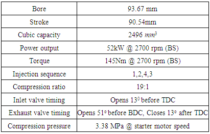
A four stroke four cylinders is tested, in-line OHV, direct injection, FSD 425 type Ford production diesel engine is used in this study. This engine is widely used in generators and commercial vehicles. For the sake of exhaust noise reduction, two exhaust mufflers are attached to the exhaust pipe. Table (1) lists its technical specifications and Figure (1) shows the test rig.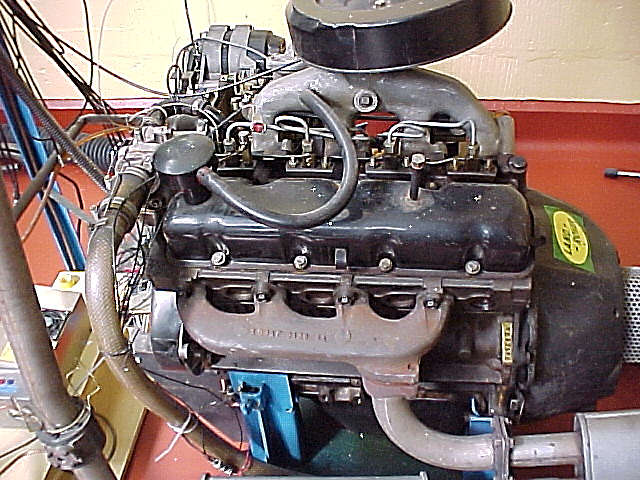 | Figure 1. Diesel engine test rig |
Table 1. Specifications of the test rig
 |
| |
|
To detect and diagnose some combustion related faults based on the vibration of engine block using conventional and advanced analysis process techniques.1. Setup a modern vibration monitoring system.2. Use time domain to represent the vibration signals and relate it to the engine events.3. Study the effects of load and speed variation on these signals; loads of 0,20,40,60 Nm and speeds of 1000, 1500 rpm.4. Seed specific and quantified fault such as exhaust valve clearance (from 0.4 to 0.0 mm).The data acquisition system used to capture the data from the engine featured the following components; In Figure (2) below the connection between the components can be seen.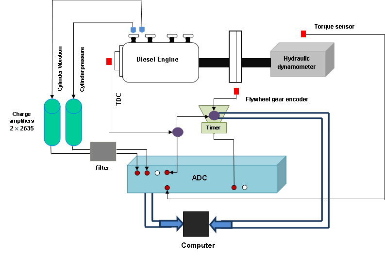 | Figure 2. Monitoring system wiring diagram |
A top mount type 4368 accelerometer is located between cylinder #1 and #2, figure (3) shows the accelerometer position between the first and the second cylinders.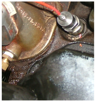 | Figure 3. Vibration accelerator type 4368 location |
The main target of this study is to acquire a real data from the engine test rig operating under normal and abnormal conditions and apply signal processing techniques for the purpose of condition monitoring. For this reason, the engine was tested under different loading conditions of 0, 20, 40 and 60 Nm at different speeds of 1000 and 1500 rpm. Only exhaust valve clearance faults were investigated. As shown in Figure (4); cylinder #1 exhaust valve clearance was altered from 0.4mm (healthy clearance) to 0 mm, 0.25mm, and 0.6mm. This simulates leakage to some extent, exhaust valve timing and in-cylinder pressure.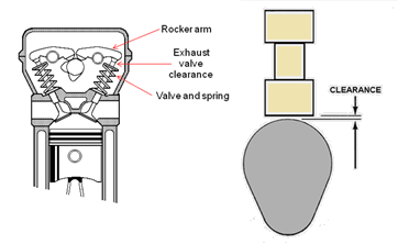 | Figure 4. Exhaust valve clearance alteration |
5. CWT of Engine Vibration Analysis
The spectrum analysis was conducted on the vibration data collected under four operational load conditions of 0Nm, 20 Nm, 40 Nm, and 60 Nm. The engine was operated at constant speed of 1000 rpm and the exhaust valve clearance was changed from 0.4mm (Healthy condition) to 0.0 mm (Faulty condition). Then the engine was operation on the same conditions at speed of 1500 rpm.Figure 5 shows the Continuous Wavelet Transform (CWT) of the diesel engine vibration. From the (CWT) representation it can be seen clearly four peaks representing the combustion events of the engine cylinders in the firing frequency from left to right (1, 2, 4, and 3). The spectral analysis shows that the major part of the energy is located in the lower frequencies (below 5 kHz), this can be seen more clearly in the CWT representation, and also it can be seen that the peak of the CWT extends to around 35 kHz.Figures 6 and 7 represent CWT of the engine vibration signals for different loads and 1000rpm engine speed, the figures show the frequency with crank angle at healthy case and vibration amplitude in meter, as load increases vibration amplitude increases.By changing the operation loads from 0 Nm to 20 Nm to 40 Nm to 60 Nm at two different speeds 1000 rpm and 1500 rpm with 0.4 clearance (healthy condition), the heights of the combustion peaks are proportional to the engine load and speed confirming that the engine vibration signals are load and speed dependent. 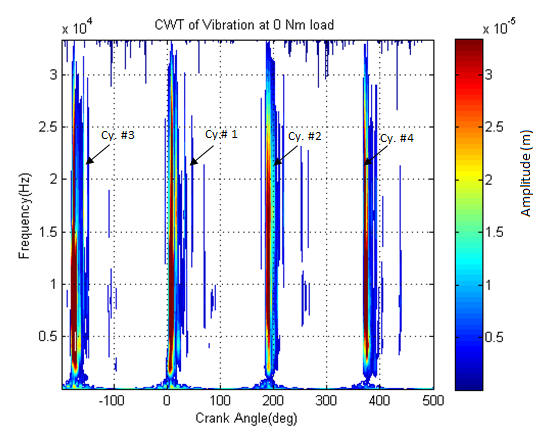 | Figure 5. CWT at 0Nm load, 1000 rpm and 0.4 mm clearance |
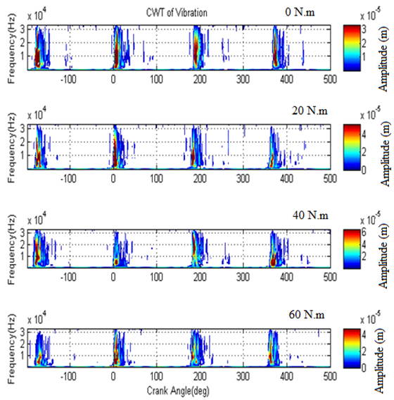 | Figure 6. CWT at 0, 20, 40, 60 Nm load, 1000 rpm and 0.4 mm clearance |
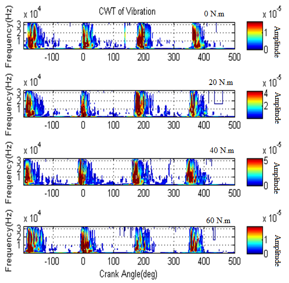 | Figure 7. CWT at 0, 20, 40, 60 Nm load, 1500 rpm and 0.4 mm clearance |
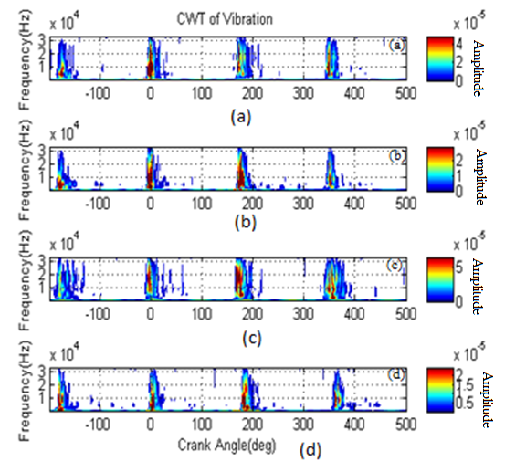 | Figure 8. CWT contour plots at 1000 rpm and 20 Nm load with the engine running (a) healthy Exhaust valve clearance 0.4mm, (b) Exhaust valve clearance 0.0mm, (c) Exhaust valve clearance 0.25mm, (d) Exhaust valve clearance 0.6mm |
6. Fault Detection and Diagnosis
According to the literature review the CWT is able to represent both low and high frequency bands energy levels with good resolution. Figure 8 shows the CWT of the engine vibration signals based on four exhaust valves clearance sets; the healthy 0.4mm contour shapes increase in the vibration signal around zero degree (TDC) at the combustion onset as shown in Figure 8 (a). Contour shapes, higher amplitude combustion excitation and a three degree delay are observed when the exhaust valve changing from 0.4mm to 0.0mm (Figure 8 (b)) which indicated that there is fault in system. The symptoms became clearer when the exhaust valve clearance increasing from 0.0mm to 0.25mm (Figure 8 (c)) and to 0.6mm (Figure 8 (d)).
7. Conclusions
The study of diesel engine vibration signals can be investigated in the time-frequency domain by different methods such as Winger-Ville distribution, conventional Fourier based frequency analysis, and Wavelet transform.Continuous wavelet transform was chosen in this study to because it has got some properties which make it better than other time-frequency techniques in analyzing such impulsive signals like diesel engine vibration signals. These properties are higher resolution and better localization characteristics.CWT time-frequency analysis technique is capable of revealing conditions indicating information embedded in the vibration signals in which the time, frequency and amplitude information can be observed. The CWT determines the signal's energy bands, and the results of the analysis of the engine vibration signals confirm that the CWT is most sensitive to low frequency information. CWT was successful in detecting the exhaust valve clearance faults in diesel engine.Continuous Wavelet Transform (CWT) was the most powerful vibration technique for fault detection and diagnosis, and showed distinctive capability over time and frequency domain.
References
| [1] | Reghuveer M. Rao. and Ajit S. Bopardikar. Wavelet Transform, Add Longman, Inc. 1998, ISBN 0-201-63463-5. |
| [2] | Bernard Challen and Rodica Baranescu, Diesel Engine reference Book, 3rd Edition, Society of Automotive Engineer, 1999, ISBN 0 7506 2176 1, pp.667-670. |
| [3] | S. D. Haddad and D. A. Howard, ‘Analysis of piston slap-induced noise and assessment of some methods of control in diesel engine’, SAE Paper 800517,1980. |
| [4] | Nurhadi, Bagiasna and Wedianto, Signature Analysis of 4-stroke 1-cylinder engine, Society of Automobile Engineers, Warrendale, PA, 1993, SAE technical Paper 932011. |
| [5] | F. Gu, A. D. Ball and K. K. Rao. Diesel injection dynamic modeling and estimation of injection parameters from impact response. Part 2: Prediction of injection parameters from monitored vibration. Proceeding Of Mechanical Engineers Part D-Journal Of Automobile Engineering, University of Manchester, 1996. |
| [6] | J.H Thomas and B. A Dubuission, diagnostic method using wavelets networks application to engine knock detection. In IEEE second International Conference on System, Man and Cybernetics, 1996. |
| [7] | G. Debotton, J. Ben-Ari, R. Itzhaki and E. Sher, Vibration Signature Analysis as a fault Detection Method for SI Engine, 1998, SAE publication 980115. |
| [8] | H.T. Grimmelius, Meiler, P.P, H.L.M.M., H.L. Mass, Bonnier, J.S. Grevink and R.F. Van Kuilenburg, Three Stat-of-the-Art Methods for Condition Monitoring, IEEE Transaction on Industrial Electronics, Issue2, 1999. |
| [9] | S. Teraguchi, W. Suzuki and M. Takiguchi, Effects of lubricating oil supply on reductions of piston slap vibration and piston friction, 2001, SAE Technical Paper Series 2001-01-0566. |
| [10] | A. Alhussain, F. GU, A. Ball and A. Starr, Internal combustion engine lubricating oil condition monitoring based on vibro-acoustic measurements, University of Manchester, July 2007, Dol:10.1784/insi.2007.49.12.715. |
| [11] | A. Alhussain, A. Ball and A. Starr, On acoustic measurement-based condition monitoring of internal combustion engines, Junury 2008, Dol:10.1784/insi.2008. 50.30. |
| [12] | W, Li PhD, Study of Noise for Diesel Engine. University of Manchester 2000. |
| [13] | F. Gu, W. Li, A.D. Ball and A.Y.T. Leung, The condition monitoring of diesel engine using Acoustic measurement, Part 1, Society of Automotive Engineers, 2000. |

 Abstract
 Reference
 Full-Text PDF
 Full-text HTML