Kento Matsusaka1, Mitsunori Uemura2, Sadao Kawamura1
1Department of Robotics, Ritsumeikan University, Shiga, Japan
2Graduate School of Engineering Science, Osaka University, Osaka, Japan
Correspondence to: Kento Matsusaka, Department of Robotics, Ritsumeikan University, Shiga, Japan.
| Email: |  |
Copyright © 2016 Scientific & Academic Publishing. All Rights Reserved.
This work is licensed under the Creative Commons Attribution International License (CC BY).
http://creativecommons.org/licenses/by/4.0/

Abstract
Using resonance-based robot motion control, we design a highly energy-efficient palletizing task for 2-DOF robots. The 2-DOF robot is installed with a variable elastic mechanism that mechanically adjusts the elasticity in each joint. The tested palletizing task must solve two problems. First, it must counteract the sharply fluctuating gravity torque as the robot changes posture. To this end, it must rapidly adjust the elasticity during the robot’s motion. Second, owing to the height difference between the pallet and the table or belt conveyor, an obstacle-avoidance trajectory is required. We also propose solutions to both problems. The high energy efficiency of our motion control is experimentally confirmed in a palletizing task.
Keywords:
Palletizing task, Variable elasticity, Highly energy efficiency
Cite this paper: Kento Matsusaka, Mitsunori Uemura, Sadao Kawamura, Highly Energy-Efficient Palletizing Tasks Using Resonance-Based Robot Motion Control, Journal of Mechanical Engineering and Automation, Vol. 6 No. 1, 2016, pp. 8-17. doi: 10.5923/j.jmea.20160601.02.
1. Introduction
Vertically articulated robots are widely employed in palletizing tasks. Generally, palletizing robots repeatedly stack a pallet with products from a table or a belt conveyor at a different height. In many factories, wherein these repetitive tasks are performed for many hours, improving the energy efficiency of palletizing is crucial.To improve the energy efficiency of repetitive tasks, some researchers have proposed resonance-based robot motion control [1]. This motion control minimizes the drive motor torque required for periodic motion by adaptively adjusting the elasticity of a variable elastic mechanism attached to each joint of the articulated robot [2]. The stability of this robot motion control has been mathematically proven [1]. In the same study, reduction of the drive motor torque was experimentally demonstrated. Generally, the resonance is strictly defined for a linear system with one DOF. In contrast, the classical resonant model is inapplicable to multi-joint robots with multi-DOFs and non-linear dynamics. The non-linear robot dynamics of multi-DOFs were effectively controlled in [1]. In [3] and [4], the resonance-based robot motion control of [1] was applied to the periodic motion in the 2-DOF horizontal plane of a SCARA type robot. Consequently, a highly energy efficient pick-and-place task was realized by point-to-point (PTP) control of practical SCARA robots.The PTP control research of the SCARA type robot suggests that resonance-based robot motion control is applicable to palletizing tasks such as pick-and-place tasks. Therefore, this paper utilizes the resonance-based robot motion control in a palletizing task of vertical articulated robots. However, due to the height difference between the pallet and the table or belt conveyor, the gravity torque greatly fluctuates. Such fluctuation is absent in the SCARA type robot. Moreover, the robot tip must avoid collisions with the table or belt conveyor. Therefore, besides PTP control, a trajectory control for avoiding obstacles is required.Herein, we resolve the problems of (1) sharply fluctuating gravity torque and (2) obstacle-avoidance trajectory control. Once these problems are solved, the resonance-based robot motion control can be applied to robot palletizing tasks. Because both problems are significant in the vertical plane of the robot’s motion, the following discussion is limited to the vertical plane.(1) Sharp fluctuation of gravity torqueUemura et al. [1] theoretically demonstrated that a variable elastic mechanism can achieve highly energy-efficient periodic motions, even under gravity fluctuations. However, because the gravity torque sharply fluctuates as the robot changes posture in palletizing tasks, the elastic value must be greatly changed during the robot’s motion. Varying the elastic value requires energy, reducing the energy efficiency of the control. To solve this problem, we compensate the dominant component of the gravitational torque by a mechanism with a fixed spring constant. Moreover, we combine this mechanism with a variable elastic mechanism and an electromagnetic motor. We experimentally confirm the effectiveness of the proposed method in a 2-DOF robot arm moving in the vertical plane.(2) Trajectory control for avoiding obstaclesIn the resonance-based robot motion control, the motion pattern of the robot is basically a harmonic oscillation. The pick-and-place tasks of the SCARA type robot in [3] and [4] were achieved by setting the pickup and placement points to the peak values of the harmonic oscillation. However, palletizing tasks also require a trajectory for collision avoidance with the table or belt conveyor.To solve this problem for a 2-DOF robot arm in the vertical plane, we set the angular frequency ratio of each harmonic oscillation to 2/1. We also experimentally verify the effectiveness of the proposed method installed in a 2-DOF robot arm.The remainder of this paper is organized as follows. In Sections 2 and 3, we describe the drive system of the robot and propose the gravity countermeasure, respectively. In Section 4, we define the investigated palletizing task and propose the obstacle -avoidance method. The high energy efficiency of the palletizing task is experimentally confirmed in Section 5, and the applicability of the proposed method to other vertical articulated palletizing robots is discussed in Section 6.
2. Robot System
2.1. Parallel Drive System
The electromagnetic motor and variable elastic element installed in each joint of the robot are shown in Fig. 1. The mechanical viscosity, Coulomb friction and static friction are reduced by decreasing the gear ratio of the reduction gear attached to the drive motor. In this mechanism, the driving motor and elastic element are driven in parallel. To achieve a highly energy-efficient periodic motion, we adjust the elasticity of the variable elastic element to a suitable value for the motion.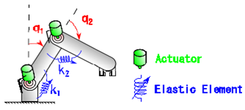 | Figure 1. Parallel drive joint of a palletizing robot |
In Fig. 1, 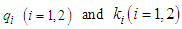 are the angle and elasticity coefficient, respectively, of the ith joint.
2.2. Variable Elastic Mechanism
Among several variable elastic mechanisms that mechanically adjust the elasticity [2], [5]–[12], we employ the variable elastic mechanism in [2]. This mechanism, schematized in Fig. 2, reduces the energy consumption of the variable elastic mechanism motor. It also has a sliding screw with a self-lock function. Therefore, it maintains a constant elastic value in the absence of a motor torque. The elasticity is determined by the geometric relationship shown in the right diagram of Fig. 2. The elasticity around the equilibrium position is uniquely determined by the nut position of the mechanism.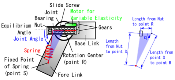 | Figure 2. Variable elastic mechanism |
3. Countermeasure of Gravity
In resonance-based robot motion control [1], the harmonic oscillation has been mathematically proven to converge to the desired trajectory, even under gravitational effects. When the motion is strictly horizontal, as in [1] and [3], the elasticity can be set to a constant value using the variable elastic mechanism of [2] after minimizing the motor torque. Therefore, no energy is consumed in changing the elasticity.In contrast, as seen in Fig. 1, when the drive motor and variable elastic mechanism in each joint operate under gravity, the perceived gravity depends on the robot’s motion. Therefore, we must generate a gravity compensation torque by driving the motor or changing the elasticity of the variable elastic mechanism. This action might significantly reduce the energy efficiency.This problem can be solved by mechanical gravity compensation. Spring-based gravity compensation has already been proposed [13]–[15]. If we can optimally compensate gravity by mechanical means, we can realize a resonance-based robot motion control using the variable elastic mechanism, and hence treat both horizontal motion and motion under gravity. However, mechanical gravity compensation increases the weight of the robot and complicates the robot mechanism. If the robot’s weight is increased by the gravity compensation mechanism, the elasticity must be increased to achieve the same natural frequency. The increased elasticity requires heavier peripheral components, such as the spring of the variable elastic mechanism, further increasing the weight of the robot. In the second-order linear dynamics of a resonant state, the motor torque compensates only the viscous component to maintain periodic motion. However, herein, the robot dynamics are nonlinear, so the inertia and elasticity terms do not completely negate at the desired harmonic oscillation frequency. To realize the desired motion, the motor must compensate the torque component and the viscosity term, which cannot be negated. Therefore, increasing the robot’s weight would increase the necessary motor torque, reducing the energy efficiency.The above discussion clarifies that when the torque component of the robot is largely contributed by the gravity term in the palletizing task, a gravity compensation mechanism is required. However, the weight of the robot increases when gravity compensation mechanisms are installed in all joints of the robot. Therefore, we partially compensate the dominant gravity torque by the gravity compensation mechanisms.Generally, when the robot is to perform various motion patterns of different magnitudes, it is theoretically difficult to select the joints that should use a gravity compensation mechanism.
4. Palletizing Task using the Double Angular Frequency Method
4.1. Palletizing Task
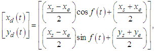
The palletizing task investigated herein is shown in Fig. 3. The shaded area indicates an obstacle such as a table or a belt conveyor (hereafter referred to as the table). The variables in Fig. 3 are defined as follows: | Figure 3. A trajectory of a palletizing task |
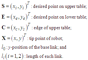 The desired trajectory is a reciprocating motion between point S on the upper table and point E on the lower table. To avoid interference with the table, the spatial trajectory must satisfy the following expressions.
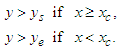 | (1) |
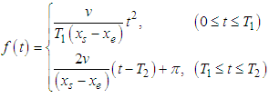
Furthermore, the ranges of the three points S, E and C (at the edge of the upper table) satisfy 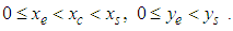 When the harmonic motion of each joint provides PTP control between points S and E, that PTP control might violate the spatial conditions of Eq. (1). This spatial trajectory problem, which arises in the presence of obstacles, was not addressed in the original resonance-based robot motion control.To find a motion pattern that satisfies the spatial conditions of Eq. (1) while maintaining the resonant state, we combine a half-cycle trajectory and a straight line trajectory, as shown in Fig. 3. Industrial robots often follow the trapezoidal velocity profile shown in Fig. 4. Here, we set the motion from time 0 to time
  as the half-cycle trajectory and the motion from time
  to time
  as the straight-line trajectory.
 | Figure 4. A trapezoidal velocity profile |
where 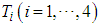 is the switching time.The motion shown in Fig. 4 is given by Eqs. (2)–(5).
 | (2) |
 | (3) |

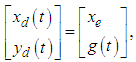 | (4) |
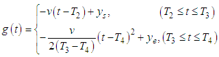 | (5) |
where and
and  denote the desired trajectory and desired velocity, respectively, and
  is the time variable.As an example, we set the points on the upper table, lower table, and edge of the upper table as
  and
and  respectively. We also set the lengths of the base link, first link and second link as
 and
and  m, respectively. These parameter values are used in practical palletizing robots. The resulting tip trajectory of the robot is described in Fig. 5.
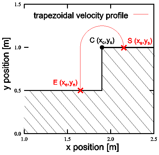 | Figure 5. Trajectory of a palletizing task following a trapezoidal velocity profile |
Fig. 6 shows the trajectories of each joint calculated from the tip trajectory equations (2) and (4). The calculation was performed by inverse kinematics.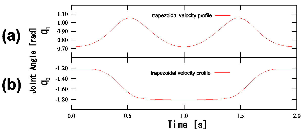 | Figure 6. Joint angle trajectory of a palletizing task following a trapezoidal velocity profile |
In Fig. 6, for every two cycles of the first joint angle (a), the second joint angle completes one cycle (b). Moreover, from their shapes, we can assume that the trajectories of both joints are harmonic oscillations. Accordingly, herein, we set the angular frequency ratio of each harmonic oscillation to 2/1.
4.2. Double Angular Frequency Method
4.2.1. Double Angular Frequency Method
Figure 7 illustrates our proposed trajectory method for connecting the desired points S and E, while preventing the tip of the robot from intercepting the table (shaded area in Fig. 7). On the basis of the results of Fig. 6, we produce the trajectory for avoiding the table by setting the angular frequency ratio of the first and second joints to 2/1.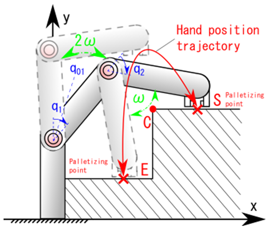 | Figure 7. A palletizing task using the double angular frequency method |
In Fig. 7,  is the first-joint equilibrium angle of the harmonic oscillation. The proposed method is governed by Eqs. (6) and (7) below.
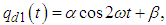 | (6) |
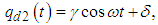 | (7) |
where are the desired joint angle trajectories and
  and
and  are the desired amplitude (offset angles) of joints 1 and 2, respectively,
  is the desired angular frequency.
4.2.2. Range Setting between Two Points
The ranges of points S and E are geometrically limited by the values of the link parameters  Furthermore, we must satisfy the following two conditions:(i) The tip velocity of the robot must be zero when the tip of the robot reaches point S or E. In other words, the proposed method requires that the angular velocity of each joint calculated by Eqs. (6) and (7) simultaneously becomes 0.(ii) In Eqs. (6) and (7), the angular frequency ratio of the first and second joints is 2/1.The two conditions (i) and (ii) ensure that the first joint angle of point S accords with the first joint angle of point E. In this case, the coordinates of points S and E must satisfy the following positional relation within the circle formed by the motion of the second link.
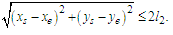 | (8) |
4.2.3. Desired Trajectory
The desired points S and E are set, and the joint angles  of point S and
  of point E are determined from inverse kinematics. In this method, the first joint angle of points S and E is set to
  Therefore, the desired trajectory of the first joint angle calculated by Eq. (6) is represented in terms of the first joint equilibrium angle of harmonic oscillation and the amplitude
  as:
as: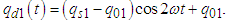 | (9) |
In Eq. (9),  can be set arbitrarily. When
  is large, the amplitude also becomes large, and the tip of the robot tends to move away from the shaded area. Here, we use the first joint equilibrium angle of harmonic oscillation as a parameter for avoiding the shaded area.The desired trajectory of the second joint angle is computed from the joint angles of S and E in Eq. (10).
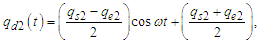 | (10) |
where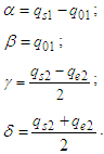 Fig. 8 compares the trajectories of a typical palletizing task and the proposed method with
  set to five different constants.
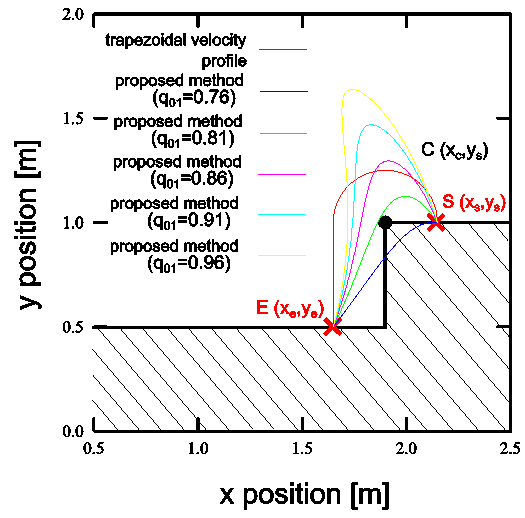 | Figure 8. Trajectories of a standard palletizing task following a trapezoidal velocity profile and the proposed method with five values of  |
As shown in Fig. 8, the y-coordinate of the peak of the tip trajectory is increased with increasing  of the first joint. Accordingly, the tip of the robot moves away from the shaded area.Figure 9 plots the time trajectory of each joint. In Fig. 9(b), the second joint angles
  are determined when points S and E are determined. Therefore, the proposed method implemented by Eq. (10) synchronizes all desired trajectories of the second joint.
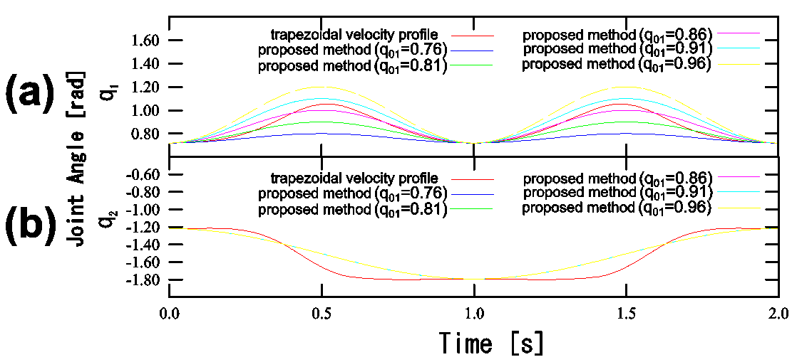 | Figure 9. Joint angle trajectory of a palletizing task following a standard trapezoidal velocity profile and the proposed method with five values of  |
5. Experiment
5.1. Palletizing Robot
The experimental setup of the 2-DOF robot for the palletizing task is shown in Fig. 10. This 2-DOF robot is driven by parallel operation of the drive motor and the variable elastic mechanism. Moreover, the gravity compensation mechanism of the first joint has a fixed spring constant [17], because the first joint is heavier than the second joint. However, in the second joint, the robot is driven by the drive motor and the variable elastic mechanism with no gravity compensation mechanism to restrain its weight. This experiment evaluates the overall performance of the robot, and the energy consumptions of the drive motor and the variable elastic mechanism.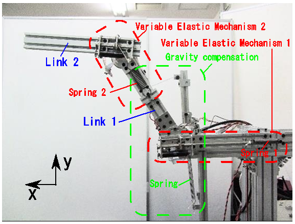 | Figure 10. Palletizing robot system |
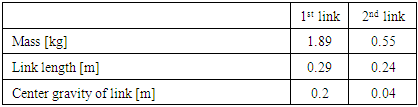
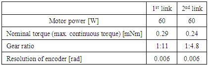
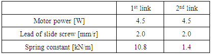
Tables 1, 2 and 3 give the robot parameters, the specifications of the drive motors and the specifications of the variable elastic mechanism, respectively. If the gear ratio of the reduction gear of the drive motor is large, the Coulomb friction and mechanical viscosity are increased; consequently, the heat energy loss increases. Therefore, the driving motor of the robot uses a low reduction gear ratio.The sampling period of the robot system is 0.001 s.Table 1. Parameters of the palletizing robot
 |
| |
|
Table 2. Parameters of the joint drive motors
 |
| |
|
Table 3. Parameters of the variable elastic mechanism
 |
| |
|
In this experiment, the coordinates of points S (on the upper table), E (on the lower table) and C (at the edge of the upper table) are specified as 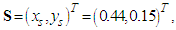
 and
and  The length of the base link is
  In the fixed gravity compensation mechanism, the spring constant is set to 167.7 N / m.
5.2. Controller
5.2.1. Elasticity Adaptation Controller
The elasticity of the variable elastic mechanism is tuned by the following adaptive control law: 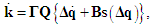 | (11) |
where are the elasticity coefficient vector and its time derivative, respectively,
  is the adaptive gain matrix,
  is the position feedback gain matrix,
 is the desired angular position vector,
  is the saturated function vector [16].The adaptive control law Eq. (11) was proposed in the resonance-based robot motion control described in [1]. The drive motor torque is minimized when the current elasticity converges to the time integrated value of Eq. (11). For convergence to the elasticity, the motor torque control input of the variable elastic mechanism is given by
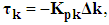 | (12) |
where  and
and  and
and  denote the elasticity calculated by Eq. (11) and the actual elasticity coefficient of the variable elastic mechanism, respectively.
  is the position feedback gain matrix.The motor torque input of the variable elastic mechanism is governed by the P control law because the slide screw has sufficient mechanical viscosity. The actual elasticity coefficient of the variable elastic mechanism is determined by the nut position of the variable elastic mechanism shown in Fig. 2. In our experiment, we control the nut position rather than elastic values.
5.2.2. Motor Controller
The control input for the drive motor torque that generates the desired periodic motion is given by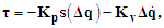 | (13) |
where  are the position and velocity feedback gain matrices, respectively.
5.3. Evaluation of Energy Consumption
To confirm the energy efficiency of the palletizing task, we calculate the energy consumption per cycle by the following equation.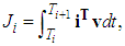 | (14) |
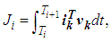 | (15) |
where denote the current vectors of the drive motor and the variable elastic mechanism, respectively. The corresponding voltages are
  and
and 
 is the start time of a motion cycle, and
  is the i-th energy consumption.After one cycle, the tip of the robot has moved from point S to E, and back to point S.
5.4. Results
The experimental results of the palletizing task are shown in Fig. 11. The results are divided into two time sections. The first section is the time of periodic motion, during which the elasticity of the variable elastic mechanism is adaptively tuned to minimize the drive motor torque by Eqs. (13) and (15). In the second section, the robot uses the elasticity converged from the first section to perform the palletizing task. In this experiment, the first section was executed for 50, providing sufficient time for the elasticity to converge to a constant. The results of Fig. 11 are detailed below.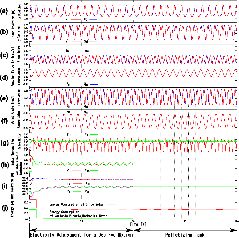 | Figure 11. Experimental results of the palletizing task (details are given in Section 5) |
In panels (a) and (b), the tip trajectory of the robot in the Cartesian coordinate system converges to the desired trajectory after the first cycle. At points S and E, the mean squared error of the tip position is approximately 10 mm.In panels (c) and (d), the noise in the actual and desired angular velocities was reduced by a digital low-pass filter. The cut-off frequency was set to 8.0 rad/s.In panels (e) and (f), the second joint angle accurately follows the desired trajectory, but the tracking accuracy of the first joint is degraded. Because the first joint’s gravity torque depends on the attitude of the second link, we attribute this deterioration to error in the gravity compensation torque.In the first cycle, of panel (g), the drive motor torque of the first joint reached the upper and lower limits of the possible output torque. However, these limits were not reached after the second cycle, indicating a reduction in the drive motor torque. Here, the absolute value of the negative direction of the motor torque exceeds the absolute value of the positive direction. Again, we attribute this effect to the attitude of the robot, which changes the gravity torque. The drive motor torque of the second joint also reduced after the second cycle.In the first time section of panels (h) and (i), the motor torque of the variable elastic mechanism is higher in the second joint than in the first joint, because there is no gravity compensation mechanism in the second joint. Therefore, the variable elastic mechanism works to reduce the output of the drive motor torque. Consequently, in the first section of Fig. 11(i), the desired nut positions corresponding to the elasticity of the second joint fluctuates periodically. The actual nut position also fluctuates periodically, and the motor torque of the variable elastic mechanism is enlarged in the second joint.In contrast, after convergence to the desired nut position in the first joint, the actual nut position settles to a constant value, and the motor torque of the variable elastic mechanism is low.In the second time section, because the nut positions of each joint are fixed as shown in Fig. 11(i), the motor torque of the variable elastic mechanism becomes 0 (Fig. 11(h)). However, because the motors of each joint must output the torque generated by the variable elastic mechanism in the first section, the drive motor torque of the second joint slightly increases in the second section.In the first time section, of panel (j), the energy consumptions of the drive motor and the variable elastic mechanism motor are both reduced after the first cycle. Furthermore, the variable elastic mechanism motor consumes much less energy than the drive motor. We confirmed that this robot approximately compensates the gravity torque even without mounting the gravity compensation mechanism in the second joint.Moreover, because of its characteristics, the variable elastic mechanism maintains a constant elasticity without outputting a torque. Therefore, in the second section, the energy consumption of the variable elastic mechanism motor falls to zero.Here, the energy consumptions of each element are calculated from the motion and the torques generated by the driving motor, the variable elastic mechanism and the gravity compensation mechanism. To achieve periodic motion in the second section, the driving motor consumes 16.8 J/cycle. Assuming that the drive motor outputs the torque generated by the variable elastic mechanism, the average required energy consumption is 176.6 J/cycle. Similarly, if the drive motor outputs the torque generated from the gravity compensation mechanism, the average required energy consumption is 167.9 J/cycle. Thus, the total energy consumption is 361.3 J. The proportion of each energy consumption is 5% (the drive motor), 49% (the variable elastic mechanism) and 46% (the gravity compensation mechanism).
6. Discussion
In this paper, we applied resonance-based robot motion control to a 2-DOF robot moving in the vertical plane, and experimentally confirmed the effectiveness of our method. However, palletizing tasks in three-dimensional space require a vertically articulated 3-DOF robot. Here, we discuss the possibility of applying the resonance-based robot motion control to such a robot by the proposed method. Therefore, we must overcome the following problems.(1) Changing moment of inertia in the pivotAs mathematically proven in [1], resonance-based robot motion control [1] realizes highly energy efficient periodic motions of nonlinear multi-DOF robots. For this reason, we consider that the proposed method is applicable to vertically articulated 3-DOF robots. However, changing the posture of a link in the vertical plane alters the moment of inertia of the pivot. These shifts might compromise the energy efficiency. In future work, we will experimentally measure the performance of the specific energy efficiency because this performance depends on the robot system.(2) Trajectory control for avoiding obstacles in three-dimensional spaceThe motions of 3-DOF vertically articulated robots in three-dimensional space can be divided into pivoting motions (first joint) and vertical plane motions (second and third joints). Therefore, the proposed method is applied to the desired trajectories of the second and third joints, which move in the vertical plane. The first joint, which performs pivoting motions, is governed by a harmonic oscillation. The angular frequency ratio of each joint is set to 1:2:1, relative to the first joint (pivot). In this case, the obstacle avoidance trajectory can be selected as shown in Fig. 8.
7. Conclusions
Applying resonance-based robot motion control, we generated periodic motions under gravity by driving the variable elastic mechanism, the drive motor and the gravity compensation mechanism in parallel. The periodic motions performed a palletizing task with high energy efficiency. For the palletizing task, we set the angular frequency ratio of each harmonic oscillation to 2/1 as the desired periodic motion. The energy efficiency of the proposed method was experimentally verified in a vertical palletizing task performed by a 2-DOF robot.
References
| [1] | M. Uemura, H. Goya and S. Kawamura, “Motion Control With Stiffness Adaptation for Torque Minimization in Multijoint Robots,” IEEE Transaction on Robotics, Vol. 30, No. 2, pp. 352-364, 2014. |
| [2] | M. Uemura, K. Matsusaka, Y. Takagi and S. Kawamura, “A stiffness adjustment mechanism maximally utilizing elastic energy of a linear spring for a robot joint,” Advanced Robotics, Vol. 29, No. 20, pp. 1331-1337, 2015. |
| [3] | H. Goya, K. Matsusaka, M. Uemura, Y. Nishioka and S. Kawamura, “Realization of High-Energy Efficient pick and place Tasks of SCARA Robots by Resonance,” Proc. of the IEEE/RSJ International Conference on Intelligent Robots and Systems, pp. 2730-2735, 2012. |
| [4] | K. Matsusaka, M. Uemura and S. Kawamura, “High Energy-Efficient SCARA Robots based on Resonance: A New Motion Control Method by using Variable Elasticity,” Proc. of the 2014 International Symposium on Flexible Automation, No. ISFA2014-55, pp. 1-6, 2014. |
| [5] | G. A. Pratt, M. M. Williamson, “Series elastic actuators,” IEEE International Conference on Intelligent Robots and Systems, pp. 399-406, 1995. |
| [6] | J. W. Hurst, J. E. Chestnutt and A. A. Rizzi, “An actuator with physically variable stiffness for highly dynamic legged locomotion,” IEEE International Conference on Robotics and Automation, pp. 4662-4667, 2004. |
| [7] | K. Koganezawa, “Mechanical stiffness control for antagonistically driven joints,” IEEE International Conference on Intelligent Robots and Systems, pp. 1544-1551, 2005. |
| [8] | A. Albu-Schaffer, O. Eiberger, M. Grebenstein, S. Haddadin, C. Ott, T. Wimbock, S. Wolf and G. Hirzinger, “Soft robotics,” IEEE Robotics & Automation Magazine, Vol. 15, Issue, 3, pp. 20 - 30, 2008. |
| [9] | Byeong-Sang Kim and Jae-Bok Song, “Hybrid dual actuator unit: A design of a variable stiffness actuator based on an adjustable moment arm mechanism,” IEEE International Conference on Robotics and Automation, pp. 1655-1660, 2010. |
| [10] | B. Vanderborght, N. G. Tsagarakis, C. Semini, R. V. Ham and D. G. Caldwell, “MACCEPA2.0: Adjustable Compliant Actuator with Stiffness Characteristic for Energy Efficient Hopping,” Proc. of the IEEE International Conference on Robotics and Automation, pp. 544-549, 2009. |
| [11] | R. Schiavi, G. Grioli and A. Bicchi, “VSA-II: a novel prototype of variable stiffness actuator for safe and performing robots interacting with humans,” Proc. of the IEEE International Conference on Robotics and Automation, pp. 2171-2176, 2008. |
| [12] | T. Menard, G. Grioli and A. Bicchi, “A Stiffness Estimator for Agonistic-Antagonistic Variable-Stiffness-Actuator Devices," IEEE Transaction on Robotics,” Vol. 30, No. 5, pp. 1269-1278, 2014. |
| [13] | N. Ulrich and V. Kumar, “Passive Mechanical Gravity Compensation for Robot Manipulators,” Proc. of the IEEE International Conference on Robotics and Automation, pp. 1536-1541, 1991. |
| [14] | Y. Ono and T. Morita, “Vertical Planar Underactuated Manipulation Using a Gravity Compensation Mechanism,” Journal of Robotics and Mechatronics, Vol, 17, No.5, pp. 553 - 559, 2005. |
| [15] | T. Nakayama, Y. Araki and H. Fujimoto, “A New Gravity Compensation Mechanism for Lower Limb Rehabilitation,” Proc. of the IEEE International Conference on Mechatronics and Automation, pp. 943-948, 2009. |
| [16] | S. Arimoto, “Control Theory of Non-Linear Mechanical Systems,” Oxford University Press, 1996. |

 Abstract
 Reference
 Full-Text PDF
 Full-text HTML