Fagner Luis Goulart Dias, Marco Antonio Rosa do Nascimento, Lucilene de Oliveira Rodrigues
Federal University of Itajubá, UNIFEI, Mechanical Engineering Institute, Itajubá, Minas Gerais, Brasil
Correspondence to: Fagner Luis Goulart Dias, Federal University of Itajubá, UNIFEI, Mechanical Engineering Institute, Itajubá, Minas Gerais, Brasil.
| Email: |  |
Copyright © 2015 Scientific & Academic Publishing. All Rights Reserved.
Abstract
Despite the significant advances achieved through the years, researchers in numerical simulation has investigated symmetry and periodicity conditions to reduce the computational time. Especially, it becomes essential this assessment in problems involving both combustion and detailed reactions mechanisms, as well as when new technologies are being evaluated. Therefore, aerothermodynamics conditions in a given periodic section, will be considered in the opposite section, assuming identical conditions in other sectors that compose the full scale domain. At this point, the definition of this representative region has been a major source of errors once the selected sector can not represent the full domain, leading to coarse approximations of the real phenomenon. In this context, this paper investigates the effects of periodicity and symmetry condition in a burner designed for flameless combustion regime. This new combustion system exhibits a strong internal recirculation and very specific characteristics that can contribute to the flow profile. Numerical simulations were performed in ANSYS FLUENT®. Based on the results, the periodicity condition in a 1/16 sector showed discordant results with those obtained in the simulations with a full scale burner and by comparing with the experimental data available. However, by employing the symmetry condition, numerical results were close to those results involving a full scale domain, reinforcing the importance of investigate carefully the use of such strategies.
Keywords:
Flameless combustion, Mild combustion, Periodicity, Symmetry, HiTAC, Low NOX burner
Cite this paper: Fagner Luis Goulart Dias, Marco Antonio Rosa do Nascimento, Lucilene de Oliveira Rodrigues, Aerodynamic Assessment of Periodicity and Symmetry Conditions in a Flameless Burner, Journal of Mechanical Engineering and Automation, Vol. 5 No. 2, 2015, pp. 80-87. doi: 10.5923/j.jmea.20150502.03.
1. Introduction
The Computational Fluid Dynamics, CFD, corresponds to a group of techniques and numerical models used in the most varied analyses involving flow. Therefore, the applications of this tool are wide, including aircraft aerodynamics research, turbo machinery, ships hydrodynamics, vehicles, power plant generation, industrial processes, biomedical engineering and others [1]. Such techniques also have a great potential in the development of new equipment and technologies.The use of CFD codes was evaluated in the design of propellers for ships [2]. In general, the numerical models for this case are developed in large cavitation tunnels, which requires great time and cost. The authors analysed the results both for a complete geometry and only one third of domain, did not find differences in the results obtained.The heat transfer was investigated the heat transfer in a group of tubes immersed in a temperature controlled environment [3]. Due to the symmetry of the tube bank and its periodicity, just one part of the geometry was modelled. However, the authors did not present in this article the effect of these simplifications in numerical results, which can be questioned the accuracy of their results.The best practices to reduce the computational time spent are assembled in analysis of thermo oscillations [4]. Among the various simplifications raised, according to the authors, the conditions of symmetry and periodicity must always be preferred. However, the authors warn that the results, especially for acoustic analysis, can suffer great changes, for example, affecting the acoustic behaviour under study.Pandey and Sivasakthivel [5] investigated the aerodynamics of the supersonic flow in a scramjet burner, fuelled with hydrogen. Analysis of injection site was done with only three injection nozzles, simplifying the problem by the periodicity condition. Despite the good results obtained, the authors did not presented a investigation or comparison about the three nozzles choice. Thus, perhaps the representation of the phenomenon presents even better results if used a different configuration.Given the studies presented, it was noted the use of periodicity conditions and simplifications in the domain geometry. However, in general, certain papers are not presented or publish clearly an discussion about the results with other possible configurations, which can be confirmed the choice of that sector as representative of full domain. In this context, although this analysis should be part of the simulation process, many researchers can be found errors by the use of these simplifications.In the case of numerical simulation involving reactive flow or combustion phenomena, the use of periodicity and symmetry conditions are even more relevant, in order to reduce the computational time and the complexity of their calculations. Thus, this paper investigates the numerical behaviour of flameless burner, based on experimental data available [6], in order to identify the most representative sector of the physical phenomenon. This combustion regime is complex, mainly due to the strong recirculation of the combustion products to the flame region. Because of the lower temperatures, the use of complex combustion codes and detailed kinetic models are required, which both greatly increases the computational time spent. Thus, it is important to investigate these assumptions, especially considering the advantages of low emissions and high burning efficiency of the flameless combustion regime.Therefore, a preliminary investigation of the symmetry and periodicity conditions was carried out. Based on the existence of 16 fuel injectors, the periodicity condition with further simplification for a 1/16 sector was investigated by comparing both the conditions of a half domain as a full domain. It was identified that the condition of maximum periodicity, 1/16, showed different results in comparison with the full domain to the velocity profile along the central axis. However, the results involving half domain showed values close to those obtained in full domain, but with reduced computational time, indicating that the use of simplifications should be used with prudence. The following are described in detail the procedure applied.
1.1. Periodicity and Symmetry Conditions
The reduction of computational time spent in the numerical simulations can be obtained through the use of the concepts of periodicity and symmetry. Basically, periodicity refers to a repeating or recurrence of a given phenomenon or a specific value within a regular interval, called the epoch, whether intervals of time or space. The periodicity can be divided into two types:
1.1.1. Translational Periodicity
In the periodicity translation, there is a definite direction where repetition can be seen, beyond a finite spatial distance associated with or given period. Thus, scalar fields and vector field components related to an overall rectangular Cartesian coordinate system, on any surface, S, in the domain are identical to the respective scalar fields and vector fields rectangular components on all surfaces obtained, corresponding to the result of translational periodicity along the S direction by an integer multiple of the period.
1.1.2. Rotational Periodicity
Considering a rotation periodicity, there is a definite periodicity axis, related to an angular period. If the domain comprises the whole section, or 2π radians, relative to the axis, the period should correspond to a fraction. In this case, the scalar and vector fields components of a global cylindrical Cartesian coordinate system, with defined periodicity axis, are considered identical to the respective scalar and vector fields of each area (domain) obtained by rotation around the axis S of an integer multiple of the angular period.
1.1.3. Symmetry
The symmetry condition is used when the physical geometry and pattern expected for flow or thermal solution has some kind of equality. In this case, can be used axes and planes present in the domain in order to allow the adoption of symmetry condition. Figures 1(a) and Figure 1(b) illustrate two regions with symmetry condition is indicated [7].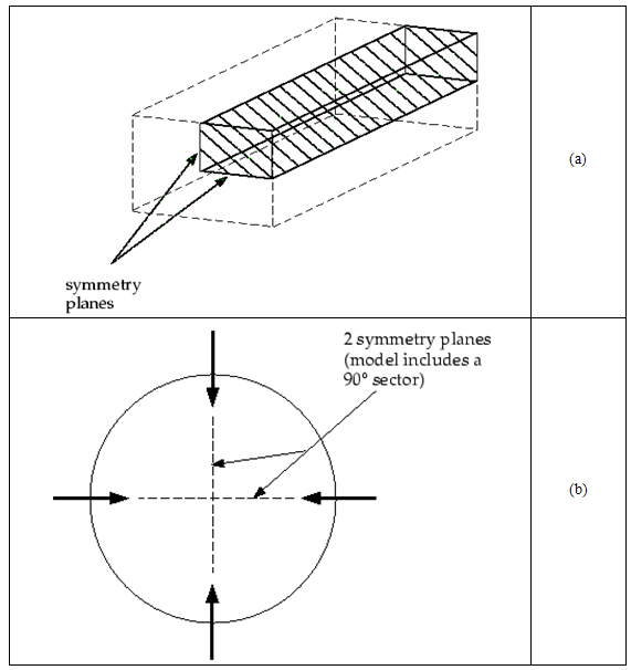 | Figure 1. Symmetry conditions applied in 1/4 domain: a) rectangular duct b) circular section (ANSYS INC., 2011) |
Figure 2a shows two cases where there is no symmetry condition. In both examples, the geometry of Figure 1.2a has symmetry, but the flow does not follow this condition, due to the effects of gravity forces that create making it asymmetrical flow. In Figure 2b the recirculation created by the injectors results in a normal flow at the desired symmetry plane, requiring the use of rotational periodicity conditions, but not symmetry.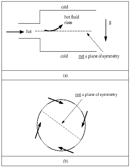 | Figure 2. Inappropriate use of symmetry (ANSYS INC., 2011) |
2. Case Study
Considering that the numerical simulations must be compared with experimental results in order to identify the behaviour of models and employed boundary conditions, was investigated the conditions of periodicity and symmetry, discussed above, in a burner designed for flameless combustion regime [6].The numerical simulations were obtained using a cluster of 40 cores, arranged in five computers, each one with eight Intel Xeon Quad-core 5420 2.5GHz / 12MB, with 16 GB RAM. The solution of the numerical equations were obtained in Second Order and the convergence criteria for residuals was 10-6 between iterations.
2.1. Initials Conditions
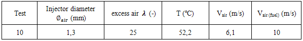
It was used for aerodynamics analysis the experimental conditions of test 2i, isothermal [6]. This test was chosen because the flameless combustion regime was later verified in combustion conditions. Table 1 contains the conditions used.Table 1. Isothermal experimental conditions [6]
 |
| |
|
The fuel input condition has been replaced by air injection at the same velocity planned in order to represent the corresponding aerodynamics condition.Table 2. CFD boundary conditions
 |
| |
|
2.2. CFD Boundary Conditions
The parameters required by the ANSYS FLUENT® as boundary conditions are shown in Table 2.
2.3. Main Burner Characteristics
The burner used in the simulations was investigated in Veríssimo doctoral thesis [6]. It is a cylindrical geometry with a central air injection and 16 fuel injectors in a radial arrangement at a distance of 15 mm from the center of burner. For burner design, the main dimensions is shown in Figure 3a.The burner is built of quartz in order to allow optical access to the interior of the combustion chamber, particularly to the reaction zone. The combustion air injection takes place from a central hole of 10 mm internal diameter and 80mm of length. The fuel injection system carried out with 16 holes, positioned around the central jet with 2mm of diameter. More details on the disposition of the injectors and the insulating material used to minimize heat losses can be seen by Figure 3b.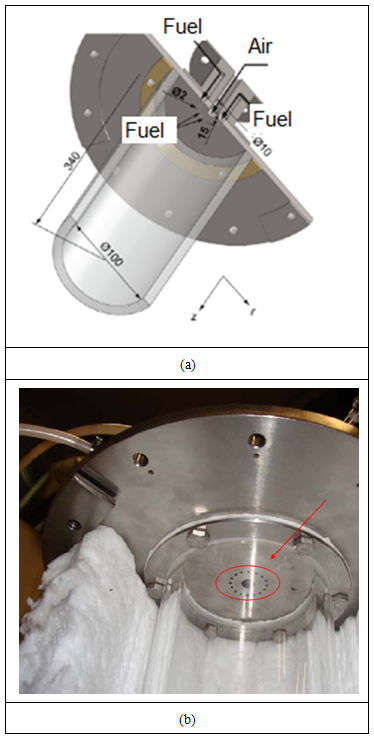 | Figure 3. Burner details: a) three-dimensional perspective b) positioning of the injectors and insulation [6] |
3. Periodicity Analyses
In the present work although simple geometry suggests the maximum periodicity in a sector containing a single fuel injector, resulting in a division of 1/16 burner should be investigated this proposition, since there may be strong distortion by internal aerodynamics. It was initially investigated a burner sector, i.e., 1/16 of the total section as SolidWorks® geometry shown in Figure 4.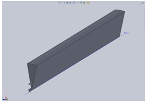 | Figure 4. Sector 1/16 of burner |
Figure 5 corresponds to simulated isothermal this sector (1/16) for the condition of 30% excess air and 25°C, as presented in Table 1.1. It is noted the presence of a strong recirculation, from which the flow has been developed. It can be seen even a small recirculation region near the wall also highlighted in Figure 5.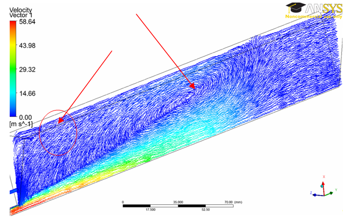 | Figure 5. Velocity vectors considering 1/16 of burner |
By the Figure 5, just it can be estimated that the flow will behave identically in other sectors to compose the complete domain. In this case, it becomes important make a comparative analysis with a full burner in order to identify possible variations in the flow along the other sectors. The full scale burner is shown in Figure 6 used in periodicity analyses.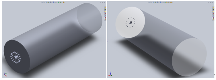 | Figure 6. Design of a full scale burner with SolidWorks® |
4. Results and Discussion
Figure 7 shows the distribution of velocity vectors in a longitudinal plane of the full burner. Note that the upper section of the plan is very similar to the profile of the flow shown in Figure 5. However at the bottom, it is observed a different flow profile, especially by the presence of secondary recirculation zones, indicating the non-periodic condition. So, consider the 1/16 sector representing whole domain can result in incorrect representation of the flow physics.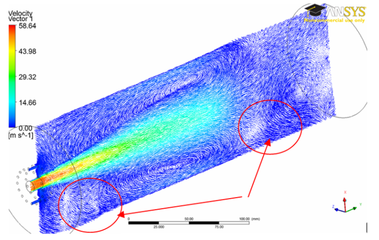 | Figure 7. Velocity vectors for the full burner |
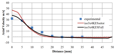
Figure 8 shows a comparison between the experimental and numerical values for the velocity vector v (considered in the main flow direction) along the central axis of the burner for both the sector and the full domain. While the measures in the central axis are independent of the reporting sector, the numerical simulation involving the entire domain will affect the flow in this region. Given the Figure 8, the numerical simulation considering full scale domain, shown by the solid line (iso3x4KESFull), was in good agreement with the experimental data.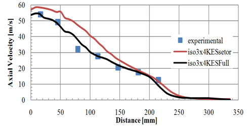 | Figure 8. Sector versus whole domain to the velocity vector along the central axis |
One of the key points that could have negatively influenced the simulations involving the sector is the quantity and quality of the mesh elements presents in this region, named vertex, as can be seen in Figure 9. In the vertex region formed by the sector, there is an enormous difficulty in filling it by tetrahedral elements, which may impair the correct solution of the transport equations in this region.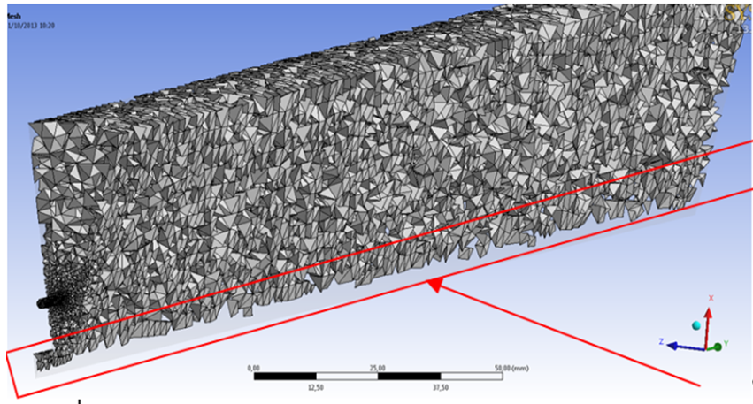 | Figure 9. Detail of mesh elements present in the central axis |
Different mesh sizes were tested, varying the number of elements and applying a local refinement, particularly in this region. In the first case, a larger amount of elements produced a very large computational time, although the results along the central axis are not improved substantially. In the second case, a refinement was carried out using smaller elements, in order to better fill the vertex region. However, despite this solution visually have solved the problem, the number of reverse flows in the output region are increased. In this case, the small size elements required to fill this region, affected also the refining of outlet zone, increased of the locations for occurrence of reverse flows.It is also observed that the numerical results of the distribution of velocity vectors in other positions, by dividing the whole domain into eight parts, not shown significant variation in the values. Other results can be analysed from this research in another planes, as shown in Figure 10, located at 45 mm of injector. The whole domain and the sector, are respectively represented by line named (iso3x4KESFull) and line named (iso3x4KESsetor).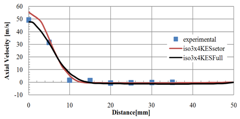 | Figure 10. Sector versus full domain for the vector radial velocity at 45 mm of injector |
In Figure 11 to Figure 15 shows the results obtained in other radial planes. It is noted that better agreement was obtained by the simulation involving the whole domain (iso3x4KESFull), although the results close to the injector, positioned at 16 mm, were in good agreement both in cases, a sector or full scale domain.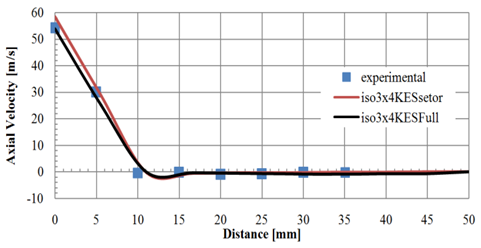 | Figure 11. Sector versus whole domain for the velocity vector at 16 mm of injector |
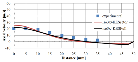
 | Figure 12. Sector versus whole domain for the velocity vector at 79 mm of injector |
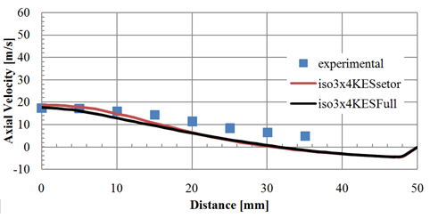
Figure 16 represents half of the burner. In the region called Symmetry (E), the symmetry condition was imposed on ANSYS FLUENT® in order to minimize the computation time.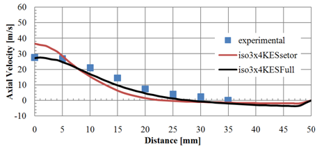 | Figure 13. Sector versus whole domain for the velocity vector at 113 mm of injector |
 | Figure 14. Sector versus whole domain for the velocity vector at 147 mm of injector |
 | Figure 15. Sector versus whole domain for the velocity vector at 181 mm of injector |
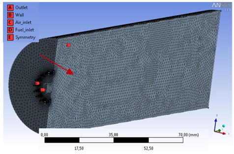 | Figure 16. Mesh used in the simulations involving half of the burner |
Figure 17 presents the distribution of the velocity vector v along the central axis. Note that the behavior of velocity vectors is similar when considering the full burner, but using a smaller computational effort. Furthermore, the choice of half burner contributes to reduced the simplifications present in the analysis of only one 1/16 sector.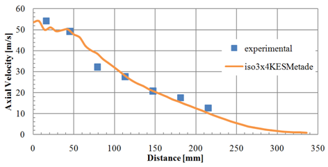 | Figure 17. Velocity vector for half burner along the central axis |
The numerical results in a radial plane 45 mm of injector are presented in Figure 18 emphasizing the good agreement with the experimental data. 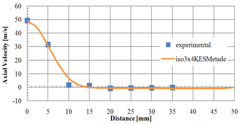 | Figure 18. The radial velocity vector to half burner in a 45 mm of injector |
5. Conclusions
It was investigated numerically the periodicity and symmetry conditions in a burner designed for flameless regime, by comparing with experimental data. Based on the results, it can be concluded that the use of the periodicity condition should be always investigated, since they showed different results when compared to the full domain, such as can be identified in this paper However, the computational effort becomes higher and may limit future combustion analysis when applied chemical reactions with detailed kinetics. One possible detailed analysis can be made with GRIMech 3.0 library [8], containing 325 intermediate reactions and 53 different chemical species, requiring enormous computational effort. In this case, as can be observed in this work, the use of symmetry condition indicated good agreement by comparing with the full domain, besides employing a reduced computational time. Also, according to results, it was noted the importance of prior analysis in order to prevent possible errors in the numerical simulation process, which can lead to erroneous interpretations.
ACKNOWLEDGEMENTS
The authors gratefully acknowledge funding agencies CAPES, CNPq and FAPEMIG for their financials supports, which were essentials to the development of this work.
References
| [1] | Choi, H.J., Zullahb M.A, Rohc H.W., Had P.S., Ohd S.Y., Leee Y.H. 2013. CFD validation of performance improvement of a 500 kW Francis turbine. Renewable Energy, v. 54, p. 111–123,doi:http://dx.doi.org/10.1016/j.renene.2012.08.049. |
| [2] | Trejo, I., Terceño, M., Valle, J., Iranzo, A., Domingo, J., 2007. Analysis of a Ship Propeller using CFD Codes. Congreso MARINE 2007, Barcelona, España, 2007. |
| [3] | Priya, M.S. and Rani, G.J. 2012. Periodic Flow Simulation and Heat Transfer. International Journal of Engineering Research and Applications, v. 2, n. 3, p. 2133–2144. |
| [4] | Toffole, A., Masi, M. and Lazzaretto, A. 2009. Low computational cost CFD analysis of thermoacoustic oscillations. Applied Thermal Engineering, v. 30, n. 6-7, p. 544–552, doi:10.1016/j.applthermaleng.2009.10.017. |
| [5] | Pandey K.M., and Sivasakthivel, T. 2011. CFD Analysis of a Hydrogen Fueled Mixture in Scramjet Combustor with a Strut Injector by Using Fluent Software. International Journal of Engineering and Technology, v. 3, n. 2, p. 109–115. |
| [6] | Veríssimo, A.S. 2011. Estudo Experimental de uma Câmara de Combustão Operando no Regime de Combustão sem Chama Visível. Tese de Doutorado, Lisboa, Portugal. |
| [7] | ANSYS INC. ANSYS FLUENT Theory Guide Release 14.0. 2011. Ansys Inc - Canonsburg, PA. |
| [8] | Gregory P. Smith, David M. Golden, Michael Frenklach, Nigel W. Moriarty, Boris Eiteneer, Mikhail Goldenberg, C. Thomas Bowman, Ronald K. Hanson, Soonho Song, William C. Gardiner, Jr., Vitali V. Lissianski, and Zhiwei Qin GRIMech 3.0. http://www.me.berkeley.edu/gri_mech/. |
 Abstract
 Reference
 Full-Text PDF
 Full-text HTML