-
Paper Information
- Previous Paper
- Paper Submission
-
Journal Information
- About This Journal
- Editorial Board
- Current Issue
- Archive
- Author Guidelines
- Contact Us
Journal of Mechanical Engineering and Automation
p-ISSN: 2163-2405 e-ISSN: 2163-2413
2015; 5(1): 56-66
doi:10.5923/j.jmea.20150501.07
Force Modelling in High Speed End- Milling of Super Alloys
 Abstract
 Reference
 Full-Text PDF
 Full-text HTML
Sunday J. Ojolo1, Olumuyiwa J. Agunsoye2, Oluwole Adesina3, Gbeminiyi Musbau Sobamowo1
1Department of Mechanical Engineering, University of Lagos, Akoka-Yaba, Nigeria
2Department ofMetallurgical and Materials Engineering, University of Lagos, Akoka-Yaba, Nigeria
3Department of Mechanical Engineering, Yaba College of Technology, Yaba, Nigeria
Correspondence to: Sunday J. Ojolo, Department of Mechanical Engineering, University of Lagos, Akoka-Yaba, Nigeria.
| Email: |  |
Copyright © 2015 Scientific & Academic Publishing. All Rights Reserved.
Temperature field in metal cutting process is one of the most important phenomena in machining process. Temperature rise in machining directly or indirectly determines other cutting parameters such as tool life, tool wear, thermal deformation, surface quality and mechanics of chip formation. The variation in temperature of a cutting tool in end milling is more complicated than any other machining operation especially in high speed machining. It is therefore very important to investigate the temperature distribution on the cutting tool–work piece interface in end milling operation. The determination of the temperature field is carried out by the analysis of heat transfer in metal cutting zone. Most studies previously carried out on the temperature distribution model analysis were based on analytical model and with the used of conventional machining that is continuous cutting in nature. The limitations discovered in the models and validated experiments include the oversimplified assumptions which affect the accuracy of the models. In metal cutting process, thermo-mechanical coupling is required and to carry out any temperature field determination successfully, there is need to address the issue of various forces acting during cutting and the frictional effect on the tool-work piece interface. Most previous studies on the temperature field either neglected the effect of friction or assumed it to be constant. The friction model at the tool-work interface and tool-chip interface in metal cutting play a vital role in influencing the modelling process and the accuracy of predicted cutting forces, stress, and temperature distribution. In this work, mechanistic model was adopted to establish the cutting forces and also a new coefficient of friction was also established. This can be used to simulate the cutting process in order to enhance the machining quality especially surface finish and monitor the wear of tool. The cutting force model developed can be used to predict the various forces during machining of end milling through Mechanistic approach. The model gives room for understanding of the cutting patterns and surface integrity, tool life and machine stability. The model would be useful to simulate the cutting process in order to enhance machining quality.
Keywords: Force, Temperature, Machining
Cite this paper: Sunday J. Ojolo, Olumuyiwa J. Agunsoye, Oluwole Adesina, Gbeminiyi Musbau Sobamowo, Force Modelling in High Speed End- Milling of Super Alloys, Journal of Mechanical Engineering and Automation, Vol. 5 No. 1, 2015, pp. 56-66. doi: 10.5923/j.jmea.20150501.07.
Article Outline
1. Introduction
- Machining process is one of the branches of manufacturing system that involves metal removal from a work piece to give a desired shape or geometry. It represents a substantial part of manufacturing industry today. Most manufacturing industries engaging in metal cutting processes in their operations include aerospace, automobile, chemical processing and die-mould factories as well. Machining operation comprise of substantial portion of the world’s infrastructure [1]. It is estimated that 15% of the cost of all mechanical components manufactured worldwide is derived from machining operation [2, 3]. The domestic expenditure on machining was estimated between 3% and 10% of the annual United State’s gross domestic product (GDP) i.e. $240 to $350 billion for 1998 [4, 5]. It is obvious that machining is very important in technical and economic development of a nation. Machining operations consume a huge amount of money annually worldwide. Over US$ 100 billion is spent annually worldwide on metal parts finishing processes such as turning, milling, boring and other cutting operations. It has also been noted that the machining industry converts about 10% of all the metals produced into swarfs [6].In order to improve the performance of metal cutting process, the throughput and the quality of the components produced, there is need to establish the relationship between the output variables such as tool life, cutting force, surface roughness, through the optimization of some input variables such as feed rate, depth of cut, cutting speed and this may lead to appreciable performance of machine operation. The cutting force is one of the variables that have direct or indirect effect on other output variables and is also one of the factors that influence the performance of milling operation, the tool life as well as the dimensional accuracy of the work piece. Many attempts were made in the past in analysing force patterns as an indication of tool wear of the end milling process. Comprehensive review of cutting force modelling for milling process have been done by Smith [7] and Ehman et al [8]. The first analytical approach was presented by Merchant [9], based on the shear angle determination using minimum energy principle. The model analysed the geometric relation between the shear and chip flow directions. Stephenson and Wu [10] proposed an upper bound model for oblique cutting based on numerical minimisation of weighted sum of plastic and friction work. Armaego and Whitfield [11] used the single shear plane model and assumed that chip length ratio in the oblique cutting is the same as that in orthogonal cutting obtained from the normal shear angle. Shamato and Altintas [12] proposed theoretical shear angle prediction approach in oblique machining by employing minimum energy principle with basic assumptions that the deformation occurs on a single shear plane produced discontinuity velocity. Oxley [13] introduced a new parallel sided shear zone model for the machining predictive theory by considering geometric method and influence on temperature, strain rate and strain on flow stress. Mourfki et al [14] developed a thermo mechanical model of oblique cutting for HSM; this model makes an assumption that hydrostatic pressure is constant in primary shear zone. Fontaine et al [15] applied Mourfki et al [16] model to cutting force prediction in ball end milling.The plastic deformation of metal cutting process is regarded as quasi-static since it is assumed that the inertial forces due to plastic flow may be neglected. Johnson and Mellon [17]; Yang and Park [18]; Budak et al [19]; Yun and Shao [20]; and Lazoglu [21] used mechanistic model to predict the cutting force, where the cutting force is estimated by dividing the cutting edge into small elements and applying a simple mathematical formulation. This system requires large amount of data gathered and stored in the cutting databases, the limitation is that the databases do not provide physical mechanism on the cutting process. However due to complex mechanisms such as high strain rates, high temperature gradients and combined elastic and plastic deformations the analytical models are unable to completely characterize the phenomena that occur on the rake and flank face of the cutting insert. Mechanistic model considered the effect of process noise factor (run out tool, tool wear, and inhomogeneity of the material in the process response. Montogomery and Altintas [22]; Yucesan and Altintas [23] used mechanistic models to predict the cutting force based on a method developed by Sabberwal [24] based on the assumption that the cutting force is proportional to the chip cross sectional area. Kline et al [25]; Budak and Altintas [26] used mechanistic model for force predictions and has been extended to predict associated machine component deflection and form error. Budak [27] developed a model of force prediction that was used to check available machine power but process optimization cannot be carried under unstable conditions. Based on all the analysis of the available model enumerated, and in order to predict and optimize accurate milling process, a mechanistic cutting forces model need to be developed
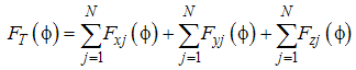
2. Model Development
- Braghini et al [28] and Vizan et al [29] stated that mechanistic model can be further divided into analytical and numerical depending on the method of solution. It has been adopted by many researchers in the analysis of the milling process. This process generally refers to the estimation of cutting force by means of the uncut chip thickness and the calibration coefficient known as the speed cutting force. To develop the mechanistic model the following assumptions were used: (i) the run out effect is ignored since the rigid system is used, (ii) there is no built up edge formation on the cutter and,(iii) wear occur at high speeds is negligible.
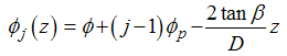
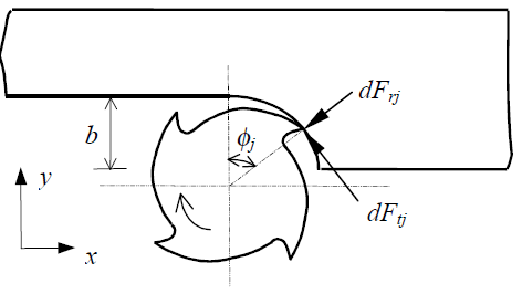 | Figure 1. The shematic diagram of the milling process |
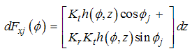
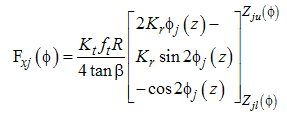
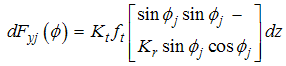
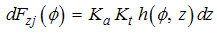
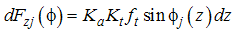
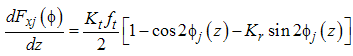
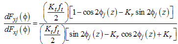
 cutting tooth, the differential milling forces,
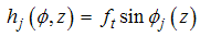
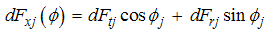
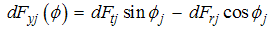
 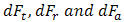 correspond to an infinitesimal element thickness in the tangential, radial and axial direction respectively. The dFtj is the differential milling force in tangential direction
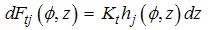 | (1) |
 | (2) |
 is the differential milling force in radial direction.
 | (3) |
 | (4) |
 | (5) |
 | (6) |
 | (7) |
 | (8) |
 | (9) |
 | (10) |
 | (11) |
 | (12) |
 is given by the equation (5)
 Then substitute for
  in equation (9),
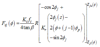 | (13) |
 | (14) |
 | (15) |
 | (16) |
 | (17) |
 | (18) |
 in equation (19) and integrate between the lower and upper limits, so we have:
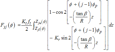 | (19) |
 | (20) |
 | (21) |
 | (22) |
 | (23) |
 | (24) |
 is given by:
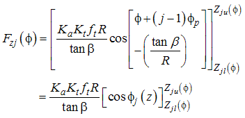 | (25) |
 | (26) |
 | (27) |
 | (28) |
 | (29) |
 | (30) |
 | (31) |
 , we have
 In this work, Arrazolla (2008) expression for coefficient of friction was adopted
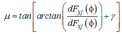 | (32) |
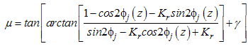 | (33) |
3. Results and Discussions
3.1. Effect of Number of flute Engagement on the Milling Operation
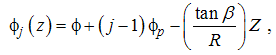
- Figure 2a-2c show the variation of axial engagement of the cut portion of the flute with immersion angle at different angular orientation of the cutter, 0°, 90° and 180° respectively. From the figure, as axial engagement of the cut portion of the flute increases, the immersion angle decreases. Also, it can be observedthat, as the cutter rotates, it generates points on the surface of work piece, these points move along the axial direction due to helical flutes, completing the surface profile at certain feed position along x-axis. This indicates that the first flutes would be the first to disengage while the fourth flute would be the last to disengage. The same result for figure 2(b) and 2(c) but only that the cutting tool engaged the work piece at different immersion angle. The immersion angle increased from -3.5 to 0 for first flute; -2.0 to 1.6 for second flute; -0.2 to 3.1 for third flute; and 1.1 to 4.8for fourth flute as the axial distance decresed from 30 mm to 0 mm.
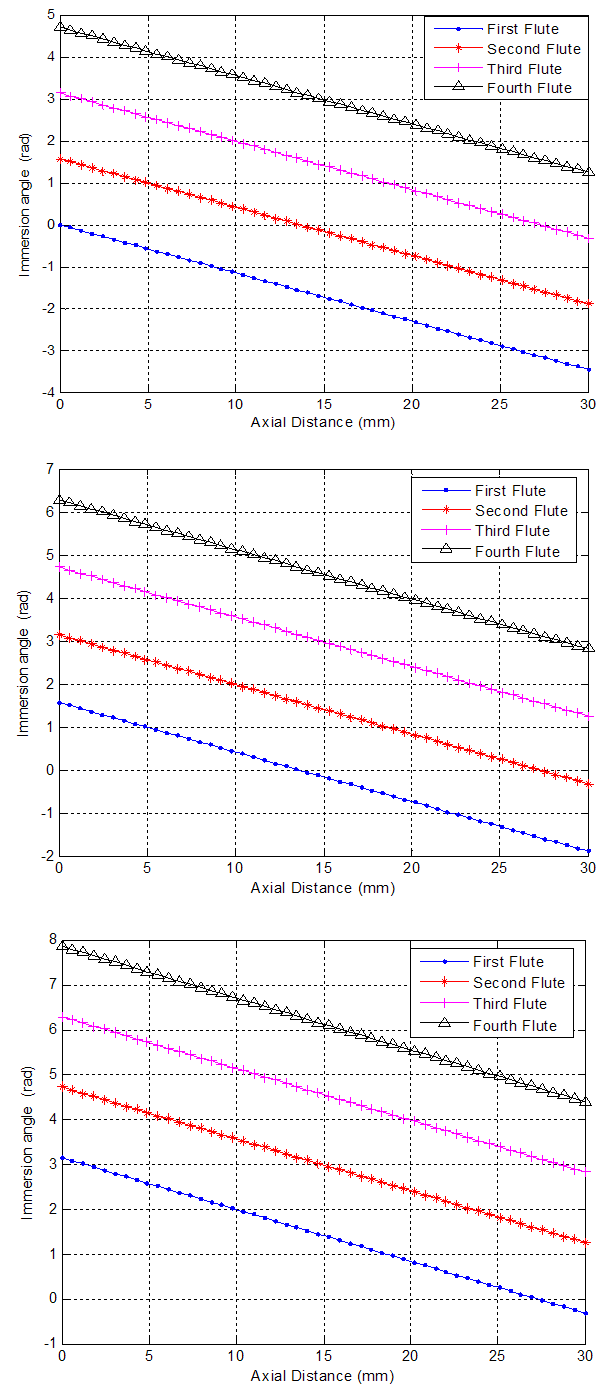 | Figure 2(a-c). The graph of immersion angle against Axial Distance |
3.2. Effect of Tool Geometryonthe Cutting Force
- Figure 3a-d show the profile of the cutting forces of different flutes with respect to the axial distance travelled by the cutting tool. The sinusoidal wave pattern shows the directional movement of the cutting tool on the work piece while is being engaged for the four number of flutes considered. The model shows that cutting forces in end milling operation may periodically fluctuate with the number of tooth passes and also cutting forces are significantly influenced by the trochoidal trajectory of the cutting tool. The cutting force fluctuates between -200N and +200N when the first and second flutes are in engagement; and -350N to +350N when the third and fourth flutes were engaged in cutting.
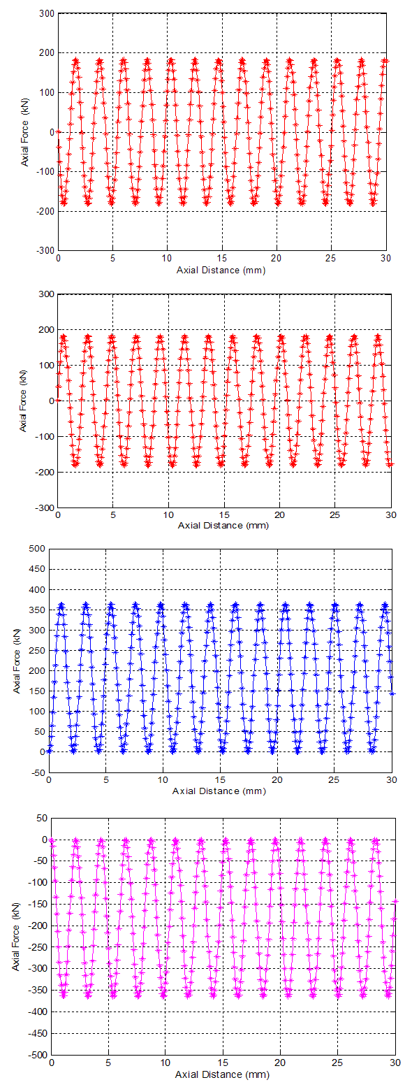 | Figure 3(a-d). Axial force against axial distance |
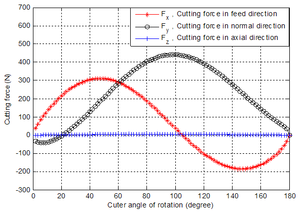 | Figure 4. Cutting forces against cutter rotation angle |
3.3. Effects of Cutting Force on the Angular Rotation of the Cutter
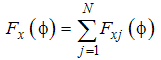
- Figure 4 shows the cutting action of the 4- flutes. The cutting force in feed direction (Fx) is a combination of tangential and radial forces,so also the normal directional force (Fy) and axial force is only force acting in axial direction. The amplitude is well predicted in Fx and Fy components while an offset appears in Fz. It is due to material flow that occurred around the cutting edge. This material flow associated with shearing occuring at the clearance face leads to ploughing force. The direction of this ploughing is mainly normal to the tool envelope and at the tool tip, this directionis very close to the z- direction. The charactristics of Fx and Fy are sinusoidal while Fz is about the straight line. In Fx and Fy cutting system, there is an intermittent cutting action of one cutting edge after another during half revolution, so that the cutting forces are varied in one revolution of the cutter. However, in Fz system cutting edges cuts simultaneously during one revolution of the cutter and there is superposition of two opposite and symmetrical forces with respect to tool axis. The result is that there is a constant z axis force.This is attributed to the fact that two cutting edges perform cutting action simultaneously during every 100° of cutting range, so there is a force during every 100° of rotation angle. The cutting force in the feed direction was maximum (300N) at 40° cuter rotation and minimum (-200N) at 150° cutter rotation. The highest cutting force (400N) was obtained in the normal direction when the cuter rotaion was 100°.
3.4. Effect of Friction on the Axial Distance in Milling Operation
- The graph in fig 5a–b show a linear relationship between the coefficient of friction and axial distance of the cutting tool, thus the higher the axial distance when the flutes are engaged in cutting action the higher the coefficient of friction between the work piece due to different immersion angle. From figure 5a it can be deduced that the coefficient of friction of first flutes is between 0.22-0.33 which means the friction along the cutting tool is not constant but varied.Lower values of friction coefficients (0.01-0.15) were obtained when the fourth flute is engaged in cutting.
4. Conclusions
- Modeling of friction and forces in end milling represents a very useful tool for predictions of operational behavior of the system. A cutting force model was developed that can be used to predict the various forces during machining of end milling through Mechanistic approach. The model gives room for understanding of the cutting patterns and surface integrity, tool life and machine stability. The model would be useful to simulate the cutting process in order to enhance machining quality.
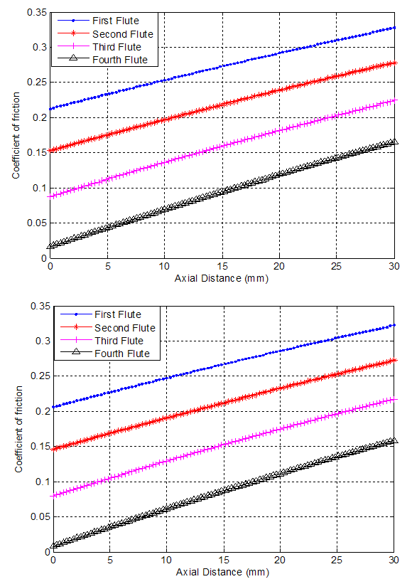 | Figure 5(a-b). Coefficient of friction against axial distance |