Tadashi Horibe, Kotaro Mori
Department of Mechanical Engineering, Ibaraki University, Ibaraki, Japan
Correspondence to: Tadashi Horibe, Department of Mechanical Engineering, Ibaraki University, Ibaraki, Japan.
| Email: |  |
Copyright © 2015 Scientific & Academic Publishing. All Rights Reserved.
Abstract
In this paper, an analytical solution for a J-shaped beam deflection is given when the beam, which is clamped at one end and free at the other, is subjected to a point load (both in-plane and out-of-plane load). We assume that the J-shaped beam is made up of two parts, i.e., a straight beam and an elliptically curved beam and that the beam is clamped at a straight end. The solution which is based on Castigliano’s theorem is deduced by using numerical integration of the modified elliptical integral and the differentiation of the beam’s strain energy. The solutions are shown in exact expressions and the effects of the curvature on the J-shaped beam deflection are clarified.
Keywords:
Beam theory, Elliptically curved beam, Deflection, Castigliano's theorem, Numerical analysis
Cite this paper: Tadashi Horibe, Kotaro Mori, In-plane and Out-of-plane Deflection of J-shaped Beam, Journal of Mechanical Engineering and Automation, Vol. 5 No. 1, 2015, pp. 14-19. doi: 10.5923/j.jmea.20150501.02.
1. Introduction
Curved beams are widely used as parts of many kinds of machines and tools. Figure 1 is an example of a curved beam, which is generally called a J-bolt or hook bolt. The curvature of the J-bolt can be represented by the elliptical curve.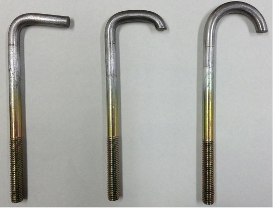 | Figure 1. Example of J-shaped beam, or hook-bolt |
For structural design, stresses and deflections of the curved beams are summarized in a textbook, e.g. [1]. For the analytical convenience, many researchers have been assumed that the curved beams have a circular curvature, e.g. [2]. The deformation of curved elastic beams including the effect of large displacement is also discussed by A. Shinohara et al. [3] and C. Gonzalez et al. [4], assuming the curvature as a circular arc. Only Dahlberg analyzed the elliptically curved beams [5] and considered both statically determinate and statically indeterminate problems for the beams.In spite of the practical use of elliptically curved beams as parts of structures, very little data on the beam with elliptical curvature is available.The purpose of the present paper is to obtain exact solutions for both in-plane and out-of-plane deflections in a J-shaped beam due to a concentrated load based on the Castigliano’s theorem and to demonstrate the accuracy and usefulness of the present approach. The solutions obtained from these formulae are compared with the alternative solutions available, including the results of a three dimensional finite element method (3- D FEM).
2. Method of Solution
2.1. In-plane Bending of J-shaped Beam
The J-shaped beam, made up of two parts, a half ellipse curve and straight line, is investigated in this paper as shown in Figure 2. The half-axes of the ellipse are denoted a and b. The beam is clamped at one end and loaded with a force P at the free end. The force P acts parallel to the plane of the ellipse. The bending stiffness of the curved beam is. The equation of the ellipse is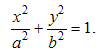 | (1) |
And we introduce the following θ as a parameter.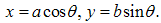 | (2) |
Therefore infinitesimal arc length ds on the ellipse is 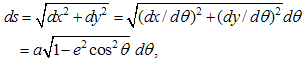 | (3) |
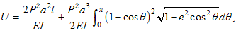
where,  is the eccentricity [6]. Here, the aspect ratio b/a = β has the relationship with e by
  .
.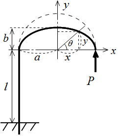 | Figure 2. Configuration of J-shaped beam |
 | (4) |
where, l is the length of straight portion of the beam. The contribution of the axial force and the shear force to the strain energy U has been neglected and we assume that cross-section of the beam is constant. Defining the integral term in Eq. (4) as 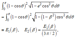 | (5) |
and applying the Castigliano's theorem, we obtain the deflection at load P as 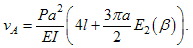 | (6) |
 | (7) |
Introducing the deflection 8Pa3/(3EI), which is the maximum deflection of the cantilever beam of span 2a, we have a normalized deflection of Eq. (6) as The integral term E2(β) is function of the parameter β only and can be evaluated by the numerical integration. The case β=1 or β=0 gives that the ellipse becomes a circle or a straight line, respectively. In those cases, the definite integral E2(β) can be analytically integrated as  | (8) |
Since the axial rigidity kiJ is defined by P/vA, we obtain  | (9) |
2.2. Out-of-plane Bending of J-shaped Beam
In this section out-of-plane deformation of J-shaped beam will be investigated. The beam is clamped at one end and loaded with a force P at the free end, see Figure 3.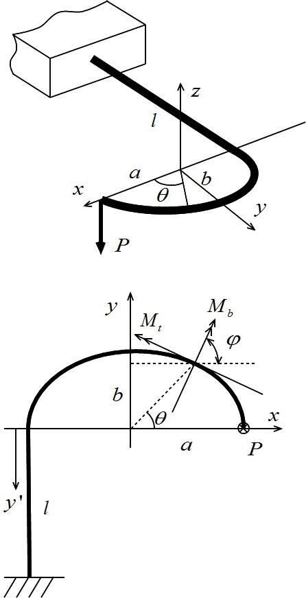 | Figure 3. Out-of-plane loading of J-shaped beam |
The force P acts perpendicular to the plane of the ellipse. The bending stiffness of the curved beam is EI and the torsional rigidity GKt.Differentiation of Eq. (1) gives: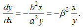 | (10) |
The infinitesimal length of the beam ds is also given: 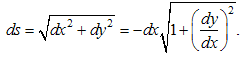 | (11) |
Introducing the angle  as shown in Figure 3, one obtains
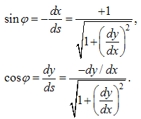 | (12) |
Next, we study the bending moment on the beam cross-section situated at angle  . The bending moment Mb and the torsional moment Mt are acting at this cross-section. Assuming its influence on the beam deflection is negligible, the shear force has been omitted. At the cross-section at angle
  , the moment equilibriums hold as follows:
 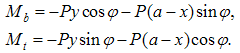 | (13) |
The elastic strain energy stored in the beam can now be calculated. We have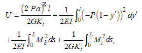 | (14) |
where L is the total arc length of the beam.Following the Castigliano's theorem, the deflection wA of the beam end at the loaded point can be calculated. Then we obtain, 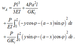 | (15) |
Substitution Eq. (12) into Eq. (15) yields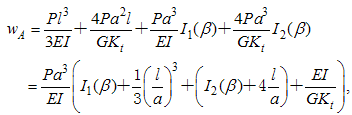 | (16) |
where I1(β), I2(β) are the integral terms in Eq. (15) and are rewritten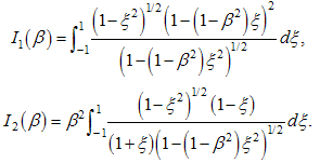 | (17) |
After inserting the values of β, which determines the configuration of the ellipse, the values of the definite integrals in Eq. (17) are obtained through the numerical integration. For the limiting case β=0 (the arc reduce to the straight line) and β=1 (circular curvature), we have | (18) |
Dividing Eq. (16) by (8Pa3)/(3EI), one obtains the following non-dimensional deflection. 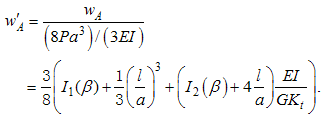 | (19) |
Axial rigidity of the beam is given as 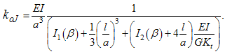 | (20) |
3. Numerical Calculation
Based on the above derivations, the deflections for both the in-plane and the out-of-plane behavior of the J-shaped beam are calculated by a closed form solution. The deflections are evaluated as a function of aspect ratio b/a or a function of beam length l/a and numerical results are compared with the 3D-FEM solutions.
3.1. In-plane Bending of J-shaped Beam
First, we evaluate the integral E2(b/a), expressed by Eq. (5). Figure 4 shows the definite integral values as function of b/a. When b/a=1, one obtains E2(1)=1. This agrees with what can be found in some handbooks. The non-dimensional displacement curves provided by Eq. (7) for J-shaped beams are plotted in Figure 5 and Figure 6. It can been seen that the deflection is proportional to the parameter b/a and have maximum values when b/a=1, i.e., circular arc. 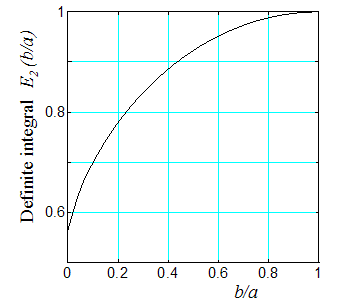 | Figure 4. Definite integral E2(β) |
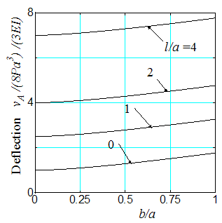 | Figure 5. In-plane non-dimensional deflection as function of b/a |
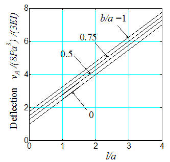 | Figure 6. In-plane non-dimensional deflection as function of l/a |
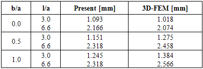
In order to validate the proposed method, the three dimensional finite element results are compared with those obtained by the present method under the following dimensions and physical properties:Young's Modulus: E=206GPa,the Poisson's ratio: ν=0.3,In-plane load: P=1000N,Beam length of straight portion: l=75, 165mm,Major axis of the ellipse: a=25mm (l/a=3.0, 6.6), Beam diameter: d=12mm,Minor axis of the ellipse:b=25, 12.5, 0.0mm.The J-beam is divided into about 10,000 quadratic tetrahedra elements as shown in Figure 7. The results obtained by the two methods are compared in Table 1 and Figure 8. Good agreement between the two methods can be observed. The difference between the two theory is mainly caused by the shear force acting on the cross-section.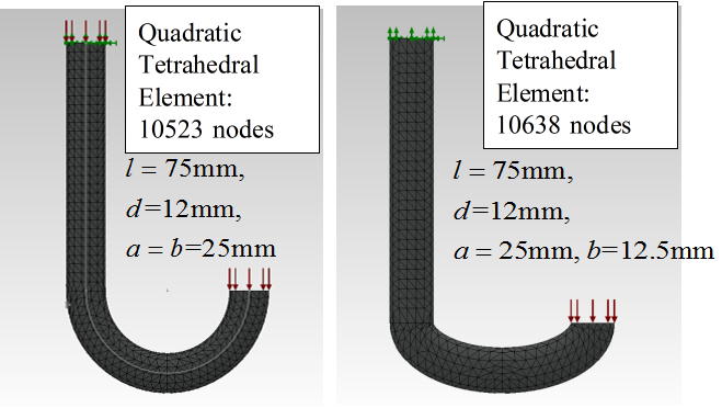 | Figure 7. 3D-FEM mesh examples of J-shaped beam (Quadratic tetrahedral element is employed) |
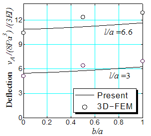 | Figure 8. Comparison between present theory and 3D-FEM results in in-plane deflection of J-shaped beam |
Table 1. Comparison of in-plane deflection at loading point
 |
| |
|
3.2. Out-of-plane Bending of J-shaped Beam
Next, we consider out-of-plane deflections of J-shaped beam. Figure 9 shows the definite integral values of I1(b/a), I2(b/a), expressed by Eq. (17). The integrals I1(b/a) and I2(b/a) are related to the bending and the torsional deformation, respectively. Hence, it is found that the torsion contributes to the deflection when b/a → 1.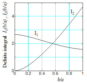 | Figure 9. Definite integrals I1(b/a) and I2(b/a) |
For a beam with a circular cross-section, we have, using ν=0.3: | (21) |
The normalized out-of-plane displacement provided by Eq.(19) for J-shaped beams are plotted in Figure 10 and Figure 11. When l/a=0 and b/a=0, the J-shaped beam coincides with the straight one of the length 2a. It can be seen that the deflections increase as the parameters b/a and l/a increase. 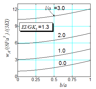 | Figure 10. Out-of-plane non-dimensional deflection of the J-shaped beam as function of b/a |
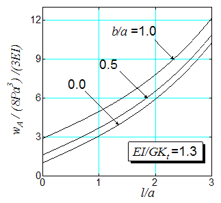 | Figure 11. Out-of-plane non-dimensional deflection of the J-shaped beam as function of l/a |
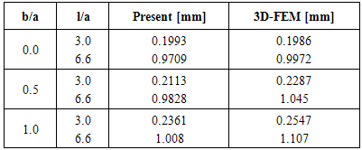
Comparison of 3D-FEM solutions with present solutions are tabulated in Table 2 and plotted in Figure 12. The J-shaped beam has the same geometrical and physical properties as those given in previous section other than out-of-plane load P=100N. In spite of concise calculation of the present approach, good agreements are again observed between the present results and the 3D-FEM ones.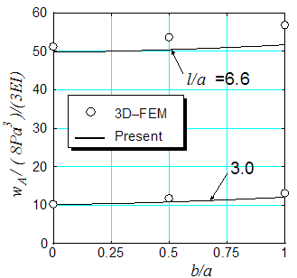 | Figure 12. Comparison of present theory and 3D-FEM results in out-of-plane deflection |
Table 2. Comparison of out-of-plane deflection at loading point
 |
| |
|
4. Conclusions
In this paper, analytical expressions are obtained for both in-plane and out-of-plane displacement of a J-shaped beam subjected to a concentrated load at free end. In the analysis, the Castigliano’s theorem is employed and the deflections of the beam are given including definite integrals and are evaluated through a numerical integration algorithm.Comparing with the three dimensional finite element method, it is demonstrated that the present method is useful and accurate, while requiring only a limited calculation.If in-plane and out-of-plane load act on a J-shaped beam simultaneously, we can estimate the deflections or stresses of the beam by superposing each results.
References
| [1] | W. C. Young, and R. G. Budynas, Roark’s Formulas for Stress and Strain (7th ed.), (2002), McGraw-Hill. |
| [2] | A Shinohara and M. Hara, “Large deflection of a circular C-shaped spring”, Int. J. Mech. Sci.. Vol.21, (1978), pp.179-186. |
| [3] | C. Gonzalez and J. LLorca, “Stiffness of a curved beam subjected to axial load and large displacements”, Int. J. Sol. and Struct., Vol.42, (2005), pp.1537-1545. |
| [4] | K, Kang and J. Han, “Analysis of a curved beam using classical and shear deformable beam theories”, KSME Int. J., Vol. 12, No.2, (1998), pp.244- 256. |
| [5] | T. Dahlberg, “Procedure to calculate deflections of curved beams”, Int. J. Engng. Ed., Vol.20, No. 3(2004), pp. 503-513. |
| [6] | M. Toda, Introduction of elliptic function (in Japanese) (2003), Nippon-hyouron-sha |
| [7] | S. Timoshenko and D. H. Young, Elements of strength of materials (5th ed.), (1974), van Nostrand Co. |
| [8] | A. Austin and J. H. Swannell, Stresses in a pipe bend of oval cross-section and varying wall thickness loaded by internal pressure, Int. J. Pres. Ves. and Piping, Vol.7 (1979), pp.167-182. |
 Abstract
 Reference
 Full-Text PDF
 Full-text HTML