-
Paper Information
- Paper Submission
-
Journal Information
- About This Journal
- Editorial Board
- Current Issue
- Archive
- Author Guidelines
- Contact Us
Journal of Mechanical Engineering and Automation
p-ISSN: 2163-2405 e-ISSN: 2163-2413
2014; 4(3): 92-100
doi:10.5923/j.jmea.20140403.02

Enhancing Cylinder Deactivation through a Clutch Concept for Mechanical Cylinder Disconnection
 Abstract
 Reference
 Full-Text PDF
 Full-text HTML
Patrick D. Fischer 1, Johannes Bergmaier 2, Hermann Pflaum 1, Karsten Stahl 1, Georg Wachtmeister 2
1Institute of Machine Elements / Gear Research Centre (FZG), Technische Universität München, Garching (Munich), Germany
2Institute of Internal Combustion Engines (LVK), Technische Universität München, Garching (Munich), Germany
Correspondence to: Patrick D. Fischer , Institute of Machine Elements / Gear Research Centre (FZG), Technische Universität München, Garching (Munich), Germany.
| Email: |  |
Copyright © 2014 Scientific & Academic Publishing. All Rights Reserved.
This work is licensed under the Creative Commons Attribution International License (CC BY).
http://creativecommons.org/licenses/by/4.0/

Losses in conventional automotive and hybrid powertrains can be reduced on both the engine and the transmission side. On the engine side for instance, cylinder deactivation can reduce the fuel consumption of an internal combustion engine (ICE). Friction losses of the non-firing cylinders still remain. Therefore, ICEs which are mechanically divided into two individual engines promise an even higher potential in terms of fuel economy. The objective of this paper is to present the concept of a clutch unit that is able to connect two ICEs. Thus, it is possible to create an innovative, cost- and fuel-efficient powertrain architecture for automotive applications: This is the concept of the Split-Crankshaft Engine (SCE). In a first step, this powertrain architecture and its particular requirements will be discussed. In a second step, a selection of proposals for crankshaft connecting clutches that have been presented in recent years will be detailed. The clutch concept of the SCE will be depicted in a third step: a switchable, electromechanically actuated clutch unit for load-dependent activation of the secondary engine. In order to reduce costs and weight as well as to minimize activation durations, the secondary engine will be started through a friction clutch. When the two sub-motors are synchronized, a form-locking, second clutch will be engaged in order to ensure the connection of both engines at high torque.
Keywords: Active Downsizing, Angular Synchronization, Cylinder Deactivation, Electromechanical Clutch Actuation, Split-Clutch Unit (SCU), Split-Crankshaft Engine (SCE)
Cite this paper: Patrick D. Fischer , Johannes Bergmaier , Hermann Pflaum , Karsten Stahl , Georg Wachtmeister , Enhancing Cylinder Deactivation through a Clutch Concept for Mechanical Cylinder Disconnection, Journal of Mechanical Engineering and Automation, Vol. 4 No. 3, 2014, pp. 92-100. doi: 10.5923/j.jmea.20140403.02.
Article Outline
1. Introduction
1.1. Motivation
- Not only the established markets USA and Europe are facing challenges in terms of reducing emissions, but also the promising automotive markets PR China and India aim for ambitious targets, as a policy update of the International Council on Clean Transportation (ICCT) [1] shows. Different technical measures can be taken to encounter this challenge on the powertrain level. On one hand, the electrification of powertrains seems to be a reasonable solution. On the other hand, the optimization of ICEs can unleash further potentials.
1.2. Objectives
- The objective of the DFG-funded research project “Development of a cost- and fuel-efficient Split-Crankshaft Engine” is therefore the reduction of fuel consumption and emissions in ICE driven automotive powertrains through a new engine layout: the Split-Crankshaft ICE (SCE). Two ICEs – a permanently firing primary engine (PE) and a secondary, switchable engine (SE) with independent crank- and valve trains – are to be serially arranged and (dis-)connected through a special coupling unit, the Split-Clutch Unit (SCU). The Institute of Internal Combustion Engines (LVK) is responsible for the PE and SE whereas the Gear Research Centre (FZG) – also at the Technische Universität München – develops the SCU.The matters presented in this paper extend the results previously published from Fischer et al. [2] by new acknowledgments and recent investigation results. Additionally a special focus is put on the state of the art as well as on the explanation of the clutch engagement process.
1.3. Method and Basic Potential
- The principle utilized in this powertrain layout is not completely new: shifting the load point of the ICE by deactivating some of its cylinders is already state of the art. But unlike conventional cylinder deactivation, the SCE concept avoids friction losses originating from the not-firing cylinders. Therefore, the powertrain efficiency is increased compared to conventional cylinder deactivation. Simulation results of Bergmaier et al. [3] regarding the possible reduction of fuel consumption in different cycles over a specified reference engine are shown in figure 1. The calculated improvements represent a compromise between drivability, comfort and reduction of fuel consumption, cf. Bergmaier et al. [3].
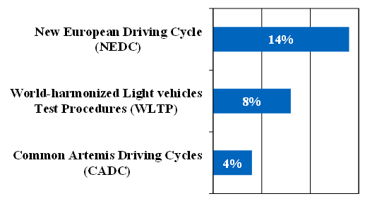 | Figure 1. Reduction in fuel consumption for the SCE concept over a reference engine for different cycles according to Bergmaier et al. [3] |
2. Concept of a Split-Crankshaft Engine (SCE)
2.1. The Powertrain-layout of the SCE Concept for a Vehicle Application
- The inline arrangement is a basic system requirement for an acceptable engine package of the SCE, although optimization for serial production is not the main focus of this research project.In order to keep the overall system complexity and therefore potential series productions costs low, the serially arranged engines have the following characteristics according to Bergmaier et al. [3]:§ Supercharged PE and naturally aspirated SE§ Both engines are 2-cylinder gasoline engines with similar dimensions§ 270° CA or 90° CA crankshaft layout for superior mass balancing§ Both engines have a 1st order mass balancing§ None of the engines has a variable valve train§ Only the PE has an electric starting device
2.2. The Powertrain-Layout of the SCE Concept for a Test Bed Application
- The previously mentioned characteristics apply for the concept engine designed to quantify the general potential of the SCE concept under consideration of a potential vehicle integration, cf. Bergmaier et al. [3]. The planned prototype for a test bed application has another crankshaft layout. It features a 180° CA “twin”-crankshaft layout with even firing intervals for better crankshaft manufacturability and lower testing costs compared to a 270° CA crankshaft layout. The engine oil characteristics are also specified (0W40), which are relevant for the frictional behavior of the SCU. The following figure shows the SCE’s powertrain-layout for its test bed application (schematically depicted).
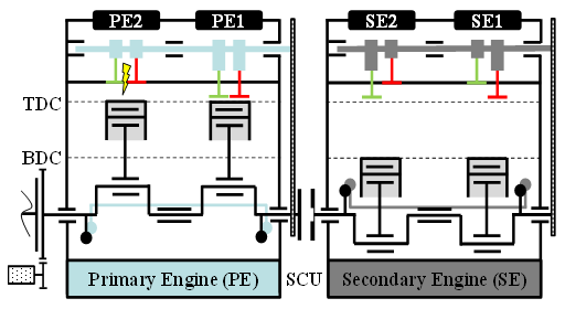 | Figure 2. Powertrain layout of the SCE concept for its test bed application (schematically depicted) |
2.3. Requirements for the Split-Clutch Unit (SCU)
- Whether the SCE concept or the test bed application is considered, the general requirements for the SCU stay the same. Not having an additional starter for the SE, for instance, brings up the two following challenges at the same time for the SCU.
2.3.1. Necessity of at Least One Friction Interface within the SCU
- The start-up functionality of the SE has to be integrated within the SCU, as the SE has to be accelerated to higher rpms than would be possible with a conventional starter. Therefore, the SCU needs at least a friction interface.
2.3.2. High Performance Friction Material for the SCU’s Friction Interface
- Furthermore, while starting-up the SE, higher overall differential speeds than in conventional start-up clutches between the primary and the secondary clutch sides occur. A high performance friction material is therefore necessary to withstand these higher sliding speeds.
2.3.3. Low Fading Tendency for the Friction Coefficient of the SCU’s Friction Interface
- The wish to keep the costs of the SCE low generates additional challenges: There should not be an oil chamber division between the SCU and the SCE, which means, that the SCU is a wet running clutch. As the engine oil 0W40 is not typical for use in clutches, a friction material with low fading tendency for the friction coefficient is necessary, which implies the use of a woven carbon friction material.
2.3.4. Closed Axial Load Loop within the SCU
- Negative effects on the engine mechanics should be as minimal as possible. Axial forces of the SCU should therefore not be introduced into the crankshafts. This can be achieved either by using additional axial load carrying bearings for the crankshafts or by implementing a closed axial load loop through a fixed shaft-in-shaft bearing.
2.3.5. Backlash-freeness in the SCU’s Circumferential Direction is Advantageous for the SCU’s Components
- As two ICEs have to be connected together, the principle of a piston engine with its positive and negative torque peaks represents a special challenge. A backlash-free connection of the torque transmitting and the axially travelling components, e.g. through diaphragm springs, is advantageous, as it prevents possible surface distress caused by alternating loads. Additionally, freedom from backlash in circumferential direction ensures a very accurate position between the crankshafts and therefore enables better NVH behavior of the powertrain.
2.3.6. Angular-Synchronization of the Engines over 720° through the SCU and its Control Unit
- Finally, getting the correct angle between the two crankshafts is probably the most important requirement of this project. In order to always keep the same firing order and particular firing intervals when switching the SCE from 2-cylinder (SCE-2) into 4-cylinder mode (SCE-4), the SCU must be capable of synchronizing both crankshafts into the right angular position. The last requirement for the SCU is therefore a 720°-angular-synchronization between the crankshafts.
2.4. Analyzing the Angular Synchronization of the Engines through the SCU for the Test Bed Application
- In order to illustrate the last requirement, it may be helpful to imagine in a first step the SCU as a simple disc clutch. Closing this clutch without any angular control system would generate a random angle between the two crankshafts. Thus, the generated 4-cylinder crankshaft layout could be wrong, as shown in figure 3. Taking into account, that the considered engine is a four-stroke engine, not only would the firing intervals be very long (360°), but two cylinders would always fire at the same time, which is unacceptable in terms of crankshaft loading.
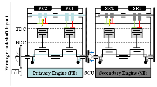 | Figure 3. Wrong 4-cylinder crankshaft layout when using a simple disc clutch without angular controlling device for the SCU (schematically depicted) |
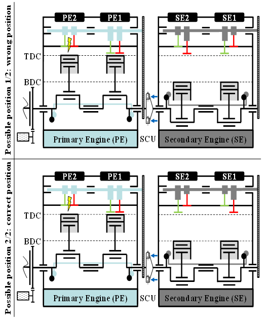 | Figure 4. Possible crankshaft positions when using a coded face gear coupling (schematically depicted) |
3. Concepts for Crankshaft Connecting Clutch Units
3.1. State of the Art
- The idea of using clutches to connect two independent ICEs is not entirely new. While some patents focus more on the connection of parallel arrangements of ICEs (cf. Bauer & Schick [4] or Yamakawa [5]), more recent patents focus also on serial arrangements of ICEs and crank trains (cf. Hofbauer & Heidemeyer [6], Huber [7] or Huber & Friedmann [8]).One of the most interesting patents for a crankshaft connecting device is certainly a self-synchronizing clutch with 720°-angular synchronization, as shown in figure 5, as it meets at least most of the previously defined requirements. This patent from Kaniut [9] is the result of many previous studies and patents beginning in the mid 1980s (cf. Kaniut & Kaniut [10], Kaniut [11] and Kaniut [12]) and ending in the 1990s with this particular patent. In the following figure, the secondary crankshaft no. 5 is started through a hydraulically actuated friction clutch (rotary feed through no. 27 and clutch plates no. 53, 54 and 55). An in-between cross helical gear pair (no. 86 and 87) connecting both the primary and the secondary side of the clutch drives a shaft no. 85 with a cam profile no. 88 – this mechanism is installed in circumferential direction of the whole clutch device – which shifts a dog clutch with pawls no. 60 every two relative revolutions between the primary crankshaft (no. 4) and the secondary crankshaft (no. 5). Because of the design of the pawls (no. 60), the dog clutch can only engage when the SE is overtaking the PE, cf. Kaniut [9].
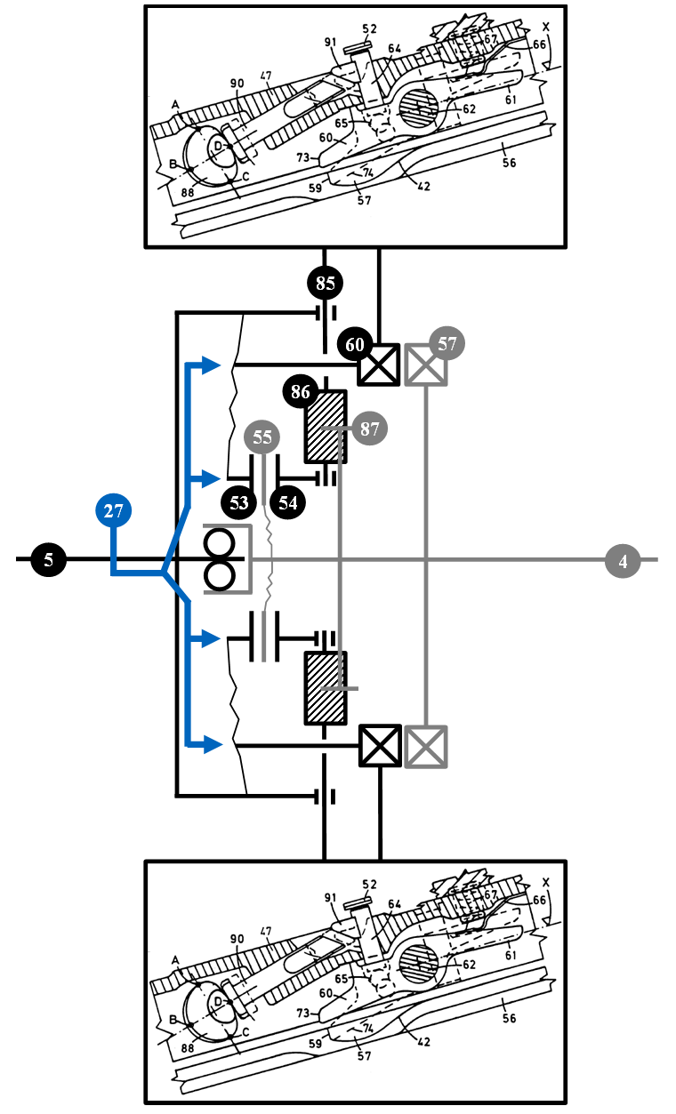 | Figure 5. Principle sketch of a self-synchronizing clutch concept for SCEs with 720°-angular synchronization according to a patent from Kaniut [9] |
3.2. Concept Analysis for the SCU’s Basic Functionality
- Because in the known literature, no clutch concept responds to the previously explained requirements, one of the objectives of this research project is to develop, design, manufacture and test a new, simple connecting clutch unit, the so-called Split-Clutch Unit (SCU), which meets all of these requirements.A concept analysis has been done for this purpose. Some of the concepts analyzed are shown in figure 6. The concepts are divided into purely friction-locking (FL) concepts and combined friction- and form-locking (FFL) concepts. The main difference between these two concept groups are that the FL concepts both start-up the SE and transmit the torque during 4-cylinder operation, whereas for FFL concepts, the friction-locking clutch only starts-up the SE while a form-locking clutch overrides the friction-locking clutch for torque transmission in 4-cylinder operation. As simulations have shown, the friction clutch in the FL concepts must transmit about four times the torque transmitted by the friction clutch for the combined FFL concepts.
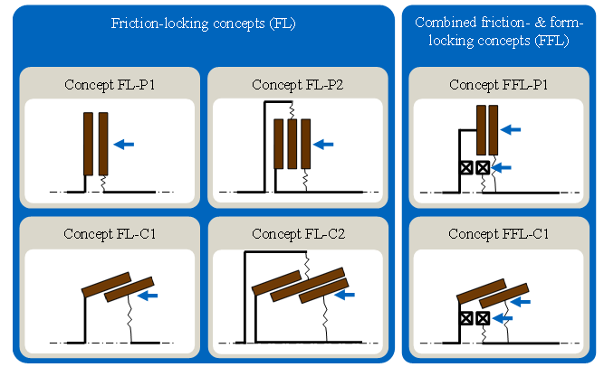 | Figure 6. Analyzed clutch concepts for the use-value analysis |
3.3. Concept Analysis for the SCU’s Actuation System
- Regarding the actuation system, another use-value analysis was performed. Possible actuation systems were:§ Hydraulic actuation§ Pneumatic actuation§ Electromagnetic actuation§ Electromechanical actuationThe electromechanical system was assessed the best, as it has numerous advantages compared to the other actuation concepts, e.g. availability of standard energy source onboard with a sufficient power density (12V network), on-demand energy consumption of the clutch actuation, etc. Furthermore, an electromechanical system allows a much simpler integration of the clutch module into potential hybridized versions of the SCE.
4. Concept of an Electromechanically Actuated Split-Clutch Unit (SCU)
4.1. Components of the SCU Concept
- As already mentioned, the most appropriate concept to meet all of the previously determined requirements is a combination of an electromechanically actuated friction- and form-locking clutch. A principle sketch of the clutch is shown in figure 7.
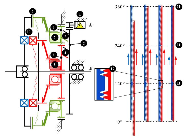 | Figure 7. Principle sketch of the SCU concept |
4.2. Engagement of the SCU Concept
- The clutch engagement begins when the BLDC motor (1) is activated and starts to revolve the rotating plate (2). In figure 8, the axial travel of the considered mechanical elements is plotted on the abscissa whereas the axis of ordinates shows the revolution of the rotating plate (2). The resulting engagement phases are explained below.
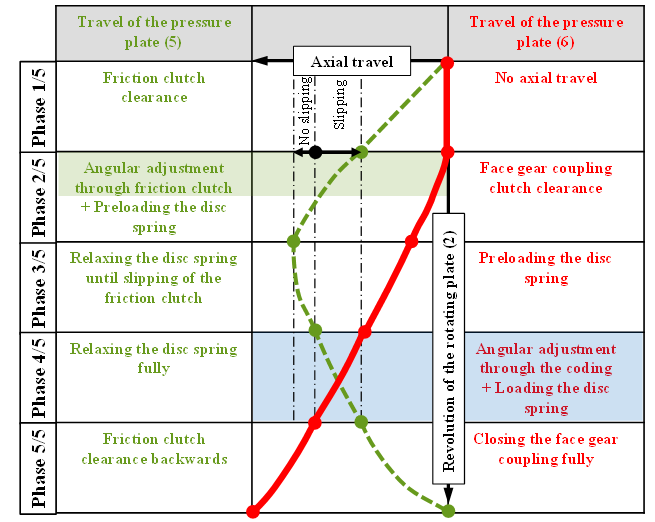 | Figure 8. Clutch engagement diagram of the SCU concept (schematically depicted) |
4.2.1. First SCU Engagement Phase
- At the end of the first phase of the SCU-engagement, the pressure plate (5) travelled the friction clutch clearance. The pressure plate (6) did not move in axial direction, as the ramp pitch of the inner ball ramp mechanism (4) is equal to zero within the revolved circle segment of the rotating plate (2).
4.2.2. Second SCU Engagement Phase
- At the beginning of the second phase of the SCU-engagement, the kiss-point for the friction plates (9) has been reached. The disc spring of the friction clutch begins to be loaded, because the pressure plate (5) is continuously travelling axially. During this time step, the acceleration of the SE to the PEs number of revolutions takes place, as well as the presetting of the right angle between the primary and the secondary crankshafts (360°-angular synchronization through the friction clutch and its control unit). Since the rotating plate (2) is still revolving, the ramp pitch of the form-locking clutch’s ball ramp mechanism (4) begins to increase slightly, so that the corresponding pressure plate (6) travels the corresponding clutch clearance.
4.2.3. Third SCU Engagement Phase
- In the third phase, the disc spring of the friction clutch (9) begins to be relaxed (changing ball ramp mechanism pitch sign) until this clutch begins to slip. At the same time, the disc spring of the form-locking clutch (10) is preloaded.
4.2.4. Fourth SCU Engagement Phase
- During the fourth phase, the disc spring of the friction clutch (9) is partly released. The secondary and the primary side of the form-locking clutch (10) still need to pass the angular offset in order to reach the right position. During this short time, the disc spring of the form-locking clutch (10) continues to be loaded.
4.2.5. Fifth SCU Engagement Phase
- During this engagement phase, the friction clutch clearance is travelled backwards by the pressure plate (5). At the same time the coded face gear coupling (10) closes fully in its only possible angular engagement position through firing the SE (superimposing of an additional, mechanical 360°-angular synchronization to reach in sum a 720°-angular synchronization).The BLDC motor has an integrated brake that is activated when the transmitted current stops at the end of the clutch engagement. The clutch actuation system therefore represents a very efficient on-demand system, as there is no need for energy to keep the SCU closed. Such a clutch actuation system and its very low energy consumption has already been investigated by Stahl et al. [15] in the EMKII-project (“Elektromechanische Kupplungsbetätigung”: Electromechanical Clutch Actuation) with a single ball ramp mechanism on a test bench at the FZG with very good results in terms of shifting time and shift reproducibility.
5. Conclusions
5.1. Summary
- As shown in this paper, the special powertrain-layout of the Split-Crankshaft Engine (SCE) generates several unconventional requirements for the connecting clutch unit – the Split-Clutch Unit (SCU) – compared to typical multidisc or start-up clutches. These requirements are e.g. higher differential speeds, untypical friction behavior because of the use of engine oil on the wet running SCU and a 720°-angular synchronization between the primary and the secondary clutch side.The idea of crankshaft connecting clutches is not new. Various patents in this field exist, but none of them meets all of the previously explained requirements at the same time, and/or they are too complex for wide use in serial production.In a use-value analysis, several concepts have been analyzed. A clutch concept with electromechanically combined friction-locking and form-locking clutches has finally been assessed as the most appropriate clutch unit concept.
5.2. Outlook
- The presented “first stage” concept has been designed and is currently being optimized in a “second stage” SCU, as shown in figure 9. It features several improvements, e.g. withstanding higher rpms, higher shifting rpm, less actuation energy because of an innovative in-between transmission, fewer parts and therefore a much better package. The basic mode of operation stays the same as the first stage clutch, as presented in this paper.
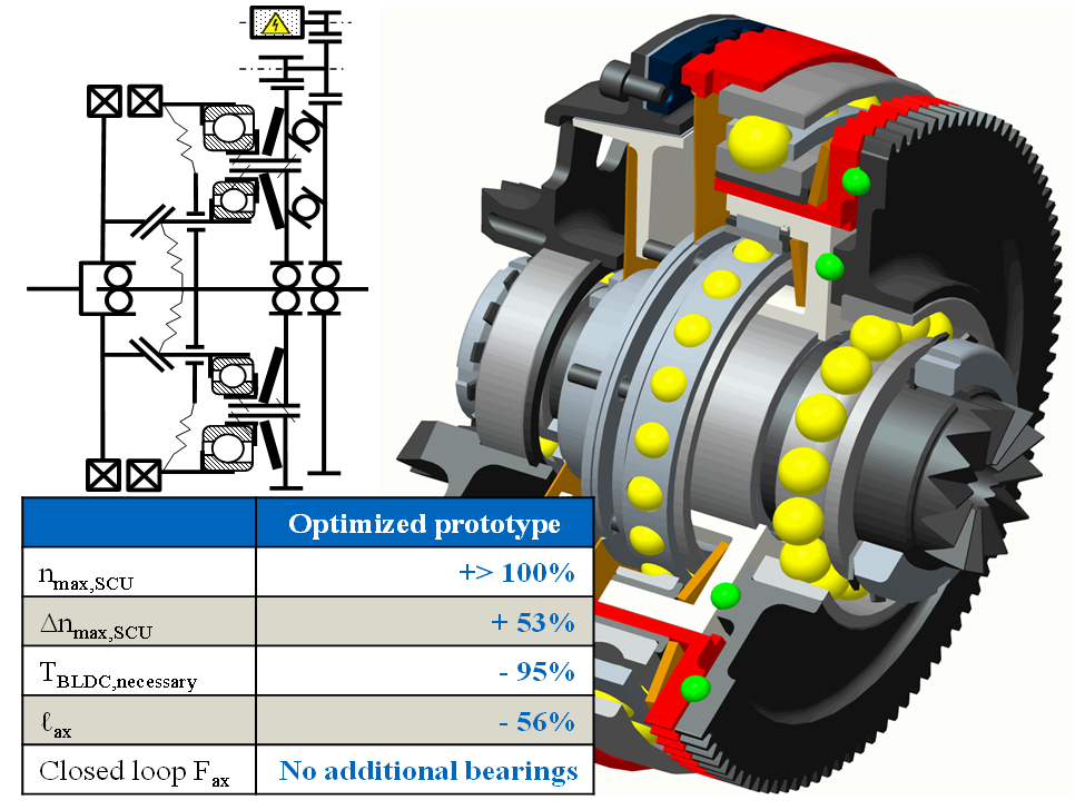 | Figure 9. Optimized “second stage” clutch concept of the SCU |
ACKNOWLEDGEMENTS
- The authors would like to thank the DFG (Deutsche Forschungsgemeinschaft / German Research Foundation) for the research grant of the project “Development of a cost- and fuel-efficient Split-Combustion Engine” STA 1198/2-2.