-
Paper Information
- Paper Submission
-
Journal Information
- About This Journal
- Editorial Board
- Current Issue
- Archive
- Author Guidelines
- Contact Us
Journal of Mechanical Engineering and Automation
p-ISSN: 2163-2405 e-ISSN: 2163-2413
2014; 4(2): 55-62
doi:10.5923/j.jmea.20140402.02
The Effect of High Temperature on Engine Performance in Kuwait Conditions
 Abstract
 Reference
 Full-Text PDF
 Full-text HTML
Mukhtar M. A. Morad, Jasem Alrajhi
Department of Automotive, And Marine Engineering Technology, College of Technological – PAAET, Studies, Kuwait
Correspondence to: Mukhtar M. A. Morad, Department of Automotive, And Marine Engineering Technology, College of Technological – PAAET, Studies, Kuwait.
| Email: |  |
Copyright © 2014 Scientific & Academic Publishing. All Rights Reserved.
There are a number of things that can go wrong with vehicles cooling system, causing the engine to run warmer than it should. Most engines today are designed to operate within a normal temperature range of about 90-115 degree℃. relatively constant operating temperature is absolutely essential for proper emissions control, good fuel economy and performance.
Keywords: Engine Performance, Kuwait Temperature
Cite this paper: Mukhtar M. A. Morad, Jasem Alrajhi, The Effect of High Temperature on Engine Performance in Kuwait Conditions, Journal of Mechanical Engineering and Automation, Vol. 4 No. 2, 2014, pp. 55-62. doi: 10.5923/j.jmea.20140402.02.
Article Outline
1. Introduction
- The demands on engine cooling systems have risen dramatically over the past two decades. Factors that have driven this rising demand are an increase in the number of the fluids that need cooling, a push for higher power output, and the implementation of stricter emission regulations. However internal combustion engines run on heat to produce energy in a mechanical form due to conversion chemical energy to heat energy. Thus all heat engines need cooling to operate, and remove energy fast enough to keep temperatures low so the engine can survive, the basic concept of the liquid cooling system is generally understood, that there is excess heat generated in the engine that must be expelled through the radiator, and that heat is carried from the engine to the radiator by the flowing liquid inside.
2. Cooling System Theory
- An Internal Combustion engine is very good at converting chemical energy to heat energy. When gasoline and air is burned with proper mixture ratio, about 14.5 parts of air for each of fuel by mass, the result is very near to 100% efficiency of the conversion in making all possible heat with minimal fuel remaining. Unfortunately the same internal combustion engine is not so good at converting heat energy into mechanical energy. Typical thermal to mechanical conversion efficiency is in the range of 25% to 35% with 50% being to the current world record (but not in a car engine). The remaining 65% or more of the available heat which is not converted to mechanical output has to be expelled or disposed of in some manner. Much of it goes out the tail pipe as heated exhaust gas. Some of it is radiated away from the exhaust system and other engine parts as infrared energy, while some more is carried away by thermal conduction to surrounding air.The science of heat transfer provides the basis for cooling system as
 Whereq= heat transferredm= massΔT=difference in temperaturecp= specific heatThe amount of heat that can be transferred from one part to another is directly proportional to the difference in temperature between the two parts. (ΔT). For the radiators, as the difference between ambient air and engine coolant temperature increases, the volume of air required to cool the fluid decrease. This law has a dramatic effect on air flow requirements as the temperature of the air approach the temperature of the fluids being cooled by radiator. The heat transfer formula from above can be re-written to apply directly to a radiator. As
 Cfmr = the required airflow generated by the cooling fan Q= the required amount of heat rejected into the air to maintain proper engine temperature.
 Mechanic Of Airflow The energy required to move something varies with the square of the speed with which it moves. The formula that describes this relationship can be written as
  Where e=energym=massv= velocityThe implication of this relationship on airflow through a radiator is straight forward.It is necessary to move more air through a radiator, it is necessary to increase the speed of the air since the effective area of the radiator remains static.Power Requirements of Airflow:The empirical relationship between airflow and the power required to generate that airflow is displayed by a well-known Fan Law, Written as
  Where hp1= power draw of the existing airflow hp2=power draw of the desired airflowcfm1 =the existing airflowcfm2=the desired airflow The implications of the above formula are far-reaching. The power draw to an increase in airflow is directly proportional to the cube of the ratio of airflow increase. Therefore, in order to increase the airflow through a radiator by 2 times, an increase in power of 8 times will be required.Impact of Fan Diameter:By increasing the diameter of the cooling fan, the same amount of airflow can be generated at a lower velocity. Since area varies with the square of diameter, velocity varies with the square of diameter, and as earlier stated, energy varies with the square of velocity. Therefore, it follows that the fan power varies inversely with the diameter to the fourth power. This relationship is expressed as
  Where hp1= power draw of the existing fanhp2= power draw of the desired fan
 = the diameter of the existing fan
 = the diameter of the desired fanThis means 10% larger fan/radiator will use 32% less horse power to move the same volume of air. It is important to use the largest radiator and fan arrangement that design constraints will allow.
3. Engine Overheating Causes
- Understand that overheating problems may be caused by a low cooling level, the radiator being plugged, the thermostat may be stuck, or other related common cooling system problems. Overheating can be caused by decreases the cooling system’s ability to absorb, transport and dissipate heat. Poor heat conductivity inside the engine because of accumulated deposits in the water jackets, a defective thermostat that does not open, poor airflow through the radiator, a slipping fan clutch, an in operative electric cooling fan, a collapsed radiator hoses, an eroded or loose water pump impeller, or even a detective radiator cap. High ambient temperature, driving at high thermal load causes consequences of overheating. The first phenomenon if gasoline engine operates at high temperature engine will start to detonate, and start to lose power under load as the combustion of heat and pressure exceed the octane rating of the fuel. Overheating can also cause pre ignition. Hot spots develop inside the combination chamber that becomes a source of ignition for the fuel. This will leads to auto-ignition even without the electric spark.
4. Test Rig and Experimentation
- The test rig as shown in Fig (1) was further developed and commissioned. The values of thermal conductivity for different compositions of radiator liquid (a mixture of Ethylene Glycol and water) were obtained by empirical relations and the liquid tested on the rig, so the function of the liquid cooling system as a whole is to precisely control and expel only the exact amount of heat, necessary to keep the engine operating in thermal equilibrium, at or near a fixed desired temperature, this temperature control function is performed by the thermostat.
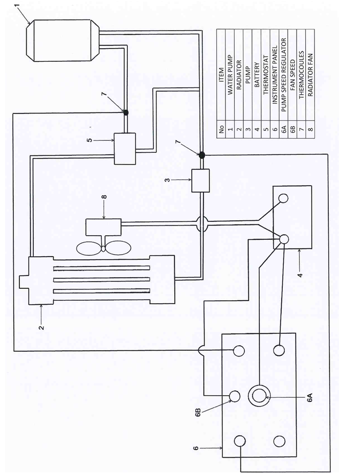 | Figure (1). The Test Rig |
5. Radiators
- A radiator is basically a heat transfer core to transfer waste heat from cooling media to the atmosphere through fins. Radiator types:Fig (2) shows the two main types of radiators
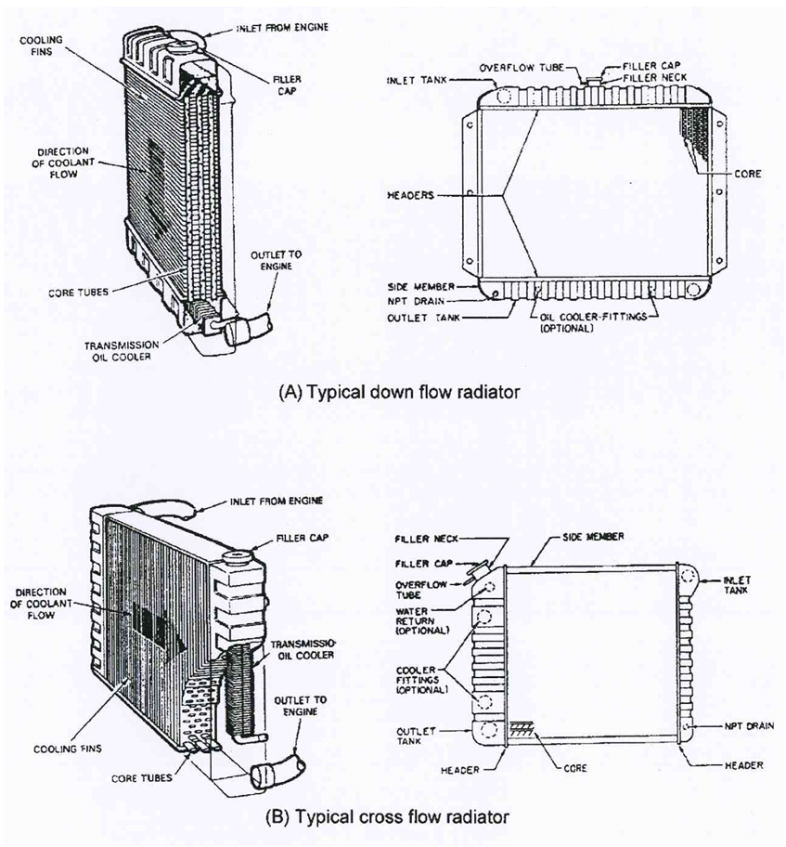 | Figure (2). Two types of radiators |
6. Results and Discussion
- In order to select the suitable coolant mixture g Ethylene- glycol and water were considered. Liquid Ethylene- Glycol has greater density than water and is performed for it's anti-freeze and anti corrosion properties. Fig (3) gives the values of thermal conductivity of the mixtures that were obtained empirically (12). It is seem from this figure that the thermal conductivity decreases with the increase in the percentage of Ethylene- Glycol with a compromise to attaining abetter anti-corrosion - anti- freeze properties and thermal conductivity, a mixture of 25% Ethylene-Glycol and 75% water is recommended for use. Although the use of propylene Glycol is becoming promising (6.8), yet it has been popular so far in Kuwait. The temperature were obtained by means of two thermocouples which were located at the inlet of the inlet of water pump and the exit of the thermostat as show in fig (1). Thus the temperature difference, ΔT, for that coolant was measured under different conditions. The inlet temperature of a mean increase of 90℃ was drived by heating the water in the boiler. The increased temperature difference could be interpreted as the increase in engine load. These different types of radiators, fans and thermostats were employed there were.
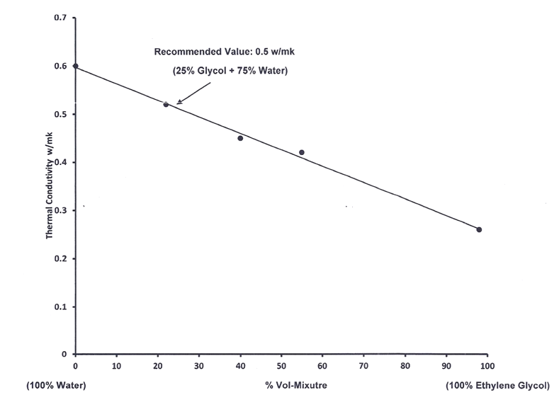 | Figure (3). Values of thermal conductivity for different coolant compositions |
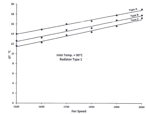 | Figure (4). Temperature Differences Against Fan Speed For Different Fans |
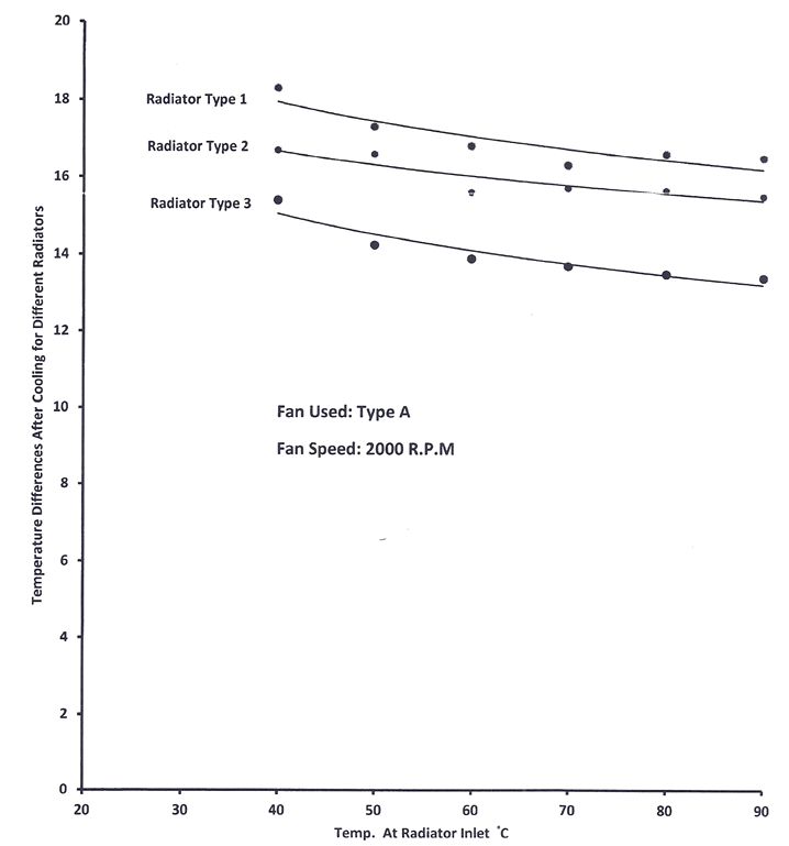 | Figure (5). Temperature Differences Against Temperature At Radiator Inlet For Different Radiators |
7. Conclusions
- A Suitable coolant, 25% Ethylene- Glycol and 75% water has been selected on the basis of it's thermal conductivity and anti-freeze properties and tested for these different types of radiators, fans and thermostats.Fan of type A. seems to be provide effective cooling of the coolant and with this fan in use, radiator of type 1, is recommended for use under Kuwait condition.Different types of thermostats do not seem to show significant effect in the cooling process. It would be worthwhile to conduct test on car engine test bed to achieve, the cooling performance with the recommends coolant, and components such as radiator and fan.