Dumitru Catalin Bursuc1, Stefan Amado2, Lucian Capitanu3, Virgil Florescu4
1“Carol I” National Defance University, Bucharest, Postcode 060173, Romania
2Technical Military Academy, Bucharest, Postcode 050141, Romania
3Tribology Department, Institute of Solid Mechanics of the Romanian Academy, Bucharest, Postcode 010141, Romania
4Mechanical Departatment, Institute of Civil Engineering, Bucharest, Postcode 050153, Romania
Correspondence to: Lucian Capitanu, Tribology Department, Institute of Solid Mechanics of the Romanian Academy, Bucharest, Postcode 010141, Romania.
| Email: |  |
Copyright © 2012 Scientific & Academic Publishing. All Rights Reserved.
Abstract
Although Metal-On-Metal (MOM) Total Hip Prostheses (THP) with self directed balls have as its greatest advantage the replacement of the sliding movement between the femoral head and the acetabulum socket specific to regular hip prostheses with the rolling movement between the balls, the socket and the femoral head, the lubrication is not well known. Laboratory tests on the ball on the flat rig showed maximum values of the coefficient of friction under 0.05, and studies of lubrication with saline solution have indicated a lubrication schedule EHL, the minimum value for the thickness of the lubrication film (hmin), measured through the contact resistance methodology, being 0.06 μm, in the operation of these prostheses are obvious trends of seizure. This paper presents some preliminary studies on lubrication in Metal-On-Metal (MOM) Total Hip Prostheses (THP) with self directed balls. Lubrication studies were made on the basis of the Spalart - Allmaras turbulence flow model, using the software Fluent. Lubricating fluid was considered incompressible. The studies were conducted in three different contact versions between the femoral head, balls and acetabular socket. The conclusion of these preliminary studies is that the lubrication (in experimental conditions adopted) is generally transient, based on rotation axes positions of femoral head and balls.
Keywords:
Metal on metal total hip prosthesis, Balls, Self directed movement, Lubrication, Femoral head rotation speed, Contact pressure
Cite this paper: Dumitru Catalin Bursuc, Stefan Amado, Lucian Capitanu, Virgil Florescu, Preliminary Study on the Lubrication in a Total Hip Prosthesis with Balls in Self-Directed Motion, Journal of Mechanical Engineering and Automation, Vol. 4 No. 1, 2014, pp. 10-42. doi: 10.5923/j.jmea.20140401.02.
1. Introduction
Given the need to continuously improve the sustainability of total hip prostheses, advances in the technology of biocompatible metal alloys and processing techniques of the surfaces, potential metal-on-metal (MOM) of total hip replacements was recently reconsidered. Although often it was reported that the first generation of hip implants used in the 1970s was a failure due to high friction moment, the new generation implants showed an encouraging clinical performance in the short and medium term, with little wear and high survival duration, so now they are increasingly used. In 1970, in a reference paper, D. Dowson[1] was the first to appreciate the lubrication of MOM total hip prosthesis is elastohydrodynamic (EHL). This approach is considered also today. Thus, Leiming Gao, Fengcai Wang, Peiran Yang and Zhongmin Jin[2] presented a simulation of elastohydrodynamic (EHL) lubrication of a metal-on-metal (MOM) total hip implant, considering both equilibrium state and the physiological load transient state, as the movement during the gait cycle in all three directions. Numerical calculations presented, based on simulations are able to easily and accurately reproduce loading and 3D movement. Because lubrication is closely related to the friction and wear of MOM hip bearings, lubrication analysis provides a better understanding of the high difference in the wear test results.In 2010 Leiming Gao et al[3] reported on the effect of surface texturing on the elastohydrodynamic lubrication analysis of metal-on-metal hip implants, that shows an advanced numerical model to simulate the mixed EHL problem of a MOM hip prosthesis with surface textured with pits. The results showed that this surface texture can have a beneficial effect on the reduction potential of the asperities contact ratio and the improvement of lubrication performances in MOM hip replacements.Qingen Meng, Leiming Gao, Feng Liu, Peiran Yang John Fisher and Zhonming Jin[4] reported that the diameter and diameter tolerance of the bearing surfaces of metal-metal hip implants and the structural supports are key factors to reduce dry contact pressures and improve the performance of hydrodynamic lubrication. On the other hand, the application of aspheric bearing surfaces can also significantly affect both contact mechanics and lubrication performance by changing the radius of curvature of a bearing surface and consequent improvement of conformity between head and cup. Pourzal R. et al[5] published a paper on micro-structural alterations in different areas of the articulated surfaces of metal on metal system, wherein show that nanoscale wear particles produced represent a limitation due to the harm of the human body. Y. Yana, A. Neville, D. Dowson, S. Williams and J. Fisher[6] published a paper related to the effect of metallic nanoparticles on biotribocorrosion behavior of metal on metal hip prostheses, which focuses on the particles in the third body and their effect on tribology and corrosion processes of bearing surfaces. A hip motion simulator integrated with an electrochemical cell was used to study the biotribocorrosion system.C.X. Li, A. Hussain and A. Kamali[7] presented some considerations on non-bearing surfaces conditions and their potential effect on the results of simulation tests for hip wear. It is shown that the potential mass loss on the non-bearing surfaces (specimens) and its contribution to the total results of gravimetric measurements are rarely mentioned in the specialized literature.Osterle W. et al[8] published a paper about the wear resistance potential of the layers deposited on Ti-6Al-4V alloy for artificial hip joint bearing surfaces, where reports on the tribological tests (sphere/ plane) that were made by them, in order to identify a suitable coating for articulated surfaces of artificial hip joints whose acetabular cups and femoral stems are made of Ti6Al4V alloy. This alloy is highly appreciated for its low weight, good compatibility and elastic properties similar to those of natural bone.With all the studies and improvements presented, the wear continues to be presented in the latest generation of THP-MOM. Nowadays, the design solutions for Total Hip Prostheses are diverse encompassing for improving the materials used for prostheses elements and reshaping geometrically and/or tribologically the load transfer path. In such context Total Hip Prostheses with rolling balls have been found as a possible viable alternative design to current industrial products, based on low friction of rolling contact, against sliding one (now used in most industrial designs). Different designs of Total Hip Prostheses with rolling bodies have been developed in order to improve the tribological performances of the artificial joint. We could mention here the design with ball train, proposed by Katsutoshi and Kiyoshi[9], the French “Supertête” prosthesis[10], or the design with conical rolling elements proposed by Imperial College of Science, Technology and Medicine of London[11]. The French design, obtained by “Fondation de l’Avenir” in collaboration with “Ministère de la Défense, Mission Innovation”, propose the insertion of a frictional contact inside a bearing. The design suggested by Imperial College of Science, Technology and Medicine of London consists in a major modification of elements between the femoral part stem neck and the modular hip prosthesis by introducing a rolling bearing with conical femoral artificial head. The bearing rotation axis corresponds with the axis of femoral stem neck, the rolling elements being guided by both the external surface of stem neck and the internal surface of the ball replacing the femoral head. But changing the contact mechanism from sliding to rolling in a hip prosthesis is not an easy task due to difficulties encountered in establishing the load transfer path, a critical characteristic of tribological behavior of joint with large influence in functionality and durability of prosthesis active elements.In the present paper, the authors focus on the original design proposed by them in[12], i.e. a MOM THP with self directed rolling balls. This constructive solution has been described in detail in[13]. Although experimental tests highlighted very low values of the rolling friction coefficient (below 0.05) and seizure tendencies have been reported[14].
2. Material and Methods
For the study of fluid flow within the joint, three variants of calculation were considered, with several cases each.1. Variant I studies the flow for a ball located between the cup and head of the joint, with consideration of undeformed geometry of surfaces in contact. The ball is tangent to spherical surfaces of the head and the cup.2. Variant II analyzes the flow for a ball in the contact area with the head, considering the strain of the two surfaces, due to an interaction force between the ball and the head of 30 N. It is considered that although deformed, the ball is not in contact with the head, between them being a gap of 0.01 mm. The assumptions adopted are: geometries bide spherical except the contact area that is considered as a flat surface normal to the centers line (like a bevel).3. Variant III analyzes the flow into the entire joint, considering some undistorted geometries. Small balls with radius lower with 0.01 mm were considered due to the FEM meshes difficulties.In all cases presented above the wall of the cup is stationary, the wall of the femoral head is rotating and balls walls are also rotating around their centers in the directions specified in each computing case.The lubricant fluid, synthetic, SBF (Simulated Body Fluid) with density 1183 kg/m3 and viscosity 0.84 Pa s (HyClone, SH30212.03) is considered incompressible. Computational Fluid Dynamics (CFD) is becoming more popular day by day, while on the other hand, the advanced technologies with huge memory and powerful processors at very low prices, which are able to solve large bi or tri dimensional numerical problems only in a few days. In another train of thoughts, commercial packages for CFD, such as FLUENT, make efficient numerical simulations easier than ever.In this paper we considered that the flow is turbulent, turbulence model being the standard Spalart-Allmaras (SA) with an equation[15].The linear model used by the Boussinesq hypothesis is: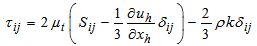 where the last term is generally ignored for Spalart-Allmaras, because k is not easily available (the term is sometimes ignored for unsupersonic flows of speeds for other models). The model with an equation is given by the following equation:
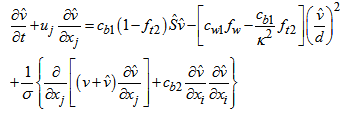 viscosity of the turbulent swirl being calculated from:
 where
where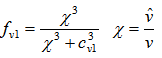 and ρ is the density, v = μ / ρ is the kinematic molecular viscosity and μ is dynamic molecular viscosity. Additional definitions are given by the following equations:
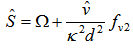 where
where 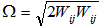 is the magnitude of the turbulence and d is the distance from the flow point to the closest wall and
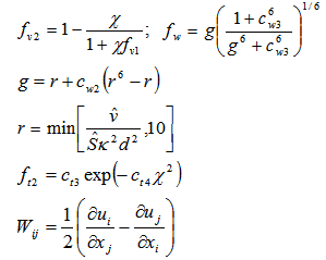 The boundary conditions are:
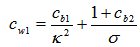
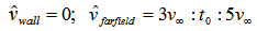 Constants are:

3. Results and Discussion
To study the flow for a ball located between the cup and head of the joint, by considering the undeformed geometry of surfaces in contact, was represented in Fig. 1 the computing domain, a fluid cell considering the ball walls, the femoral head (spherical surface with smaller radius) and the acetabular cup (spherical surface with larger radius), represented in black.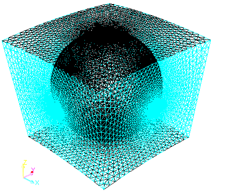 | Figure 1. The lattice with tetrahedral elements |
In blue are represented the boundary surfaces of the fluid, considering areas with atmospheric pressure. By considering this cell, the influence of neighbor balls movement on the fluid flow in the cell considered is neglected, at least in the contact area with the head and the cup, the area that presents interest.
3.1. Variant 1
Six angular speeds of the head are considered: 0.5; 1; 1.5; 2; 2.5; 3 rad/s and six slope angles of the angular speed of the ball as against the head: 0, 15, 30, 45, 60 and 750. 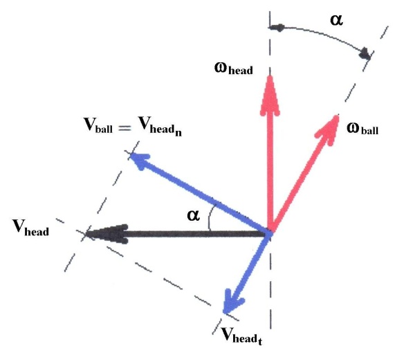 | Figure 2. Linear speeds peripheral in the contact geometric point and angular speeds of the head and the ball |
 | Figure 3. Case 6.5. The rotation velocity of the head 3 rad/s, the rotation axis of the ball inclined by 600 with respect to the rotation axis of the head |
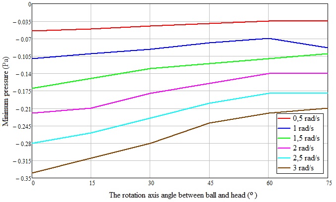
Corresponding to these values, the angular speed of the ball, as against its center, results from the kinematic condition that the peripheral speed of the head in the contact area projected in the direction normal to the rotation axis of the ball to be equal to the peripheral speed of the ball. In this plane normal to the rotation axis of the ball passing through the contact point between the ball and the head, the ball rolls without slipping on the head (Fig. 2). In the plane containing the rotation axis of the balls and their centers, sliding without rolling exists, the relative speed between the contact surfaces being Vcap t.In the following we present only the results for 3 rad/s and the rotation axis of the ball inclined by 600 with respect to the rotation axis of the head (case 6.5 Figs. 3).In Figs. 4 and 5 is presented the variation of maximum and minimum gauge pressure in the contact area depending on the angle between the rotation axis of the ball and the head and on the angular speed of the head.One can note a decrease of the maximum gauge pressure and an increase of the minimum gauge pressure in the contact area with increasing the angle between the two rotation axes.If the angular velocity of the head increases, the maximum gauge pressure increases in the contact area and the minimum gauge pressure decreases. As is observed in the pressure field represented on the surface of the ball, both in the contact area with the head and with the cup, the overpressure has a distribution area approximately equal to the depression, the forces resultant being very small.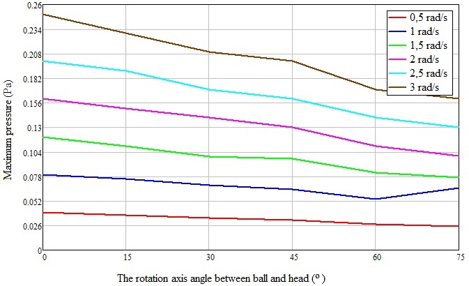 | Figure 4. Variation of maximum gauge pressure in the contact area of the cup, depending on the angle between the rotation axis of the ball and the head and on the angular speed of the head |
 | Figure 5. Variation of minimum gauge pressure in the contact area of the head, depending on the angle between the rotation axis of the ball and the head and on the angular speed of the head |
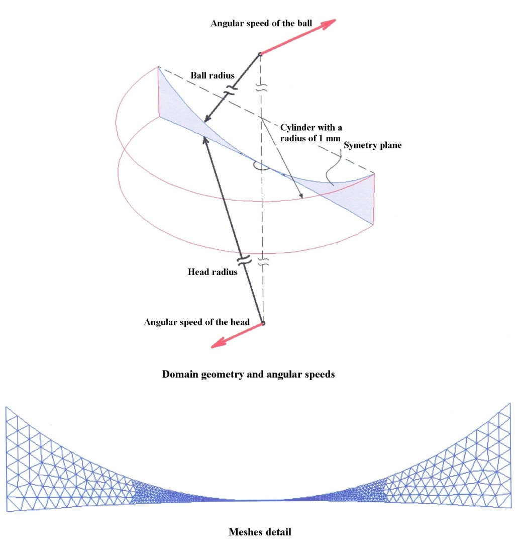 | Figure 6. The geometry of the field, angular velocities (top) and a detail of the meshes (bottom) |
3.2. Variant II
To better capture the flow in the deformed area, axes of rotation of the ball and the head were considered parallel, with the following scenarios: the ball to roll without slipping on the surface of the head (the angular velocity of the ball being thus maximum), the ball to slip and to roll on the surface of the head, the ball to not roll over the surface of the head but only to slide (its angular velocity being zero). In the figure below the angular speed vectors are perpendicular on the symmetry plane (Fig. 6).For all cases, the angular speed of the head is 0.5 rad/s, angular speed vector being oriented in the positive direction of the Oz axis. Angular speed vector of the ball is oriented in the opposite direction of the positive direction of the Oz axis.For brevity, we present below only if ωball = 4.667 rad/s (rolling without sliding) –(figs. 7 - 8).3.2.1. For the Case ωball= 4.667 rad/s (Rolling without Sliding; Figs. 7-8)Net force on the surface of the ball considered is 4.219546 e – 05 N. Figure 9 show the variation of the minimum and maximum pressure in contact area.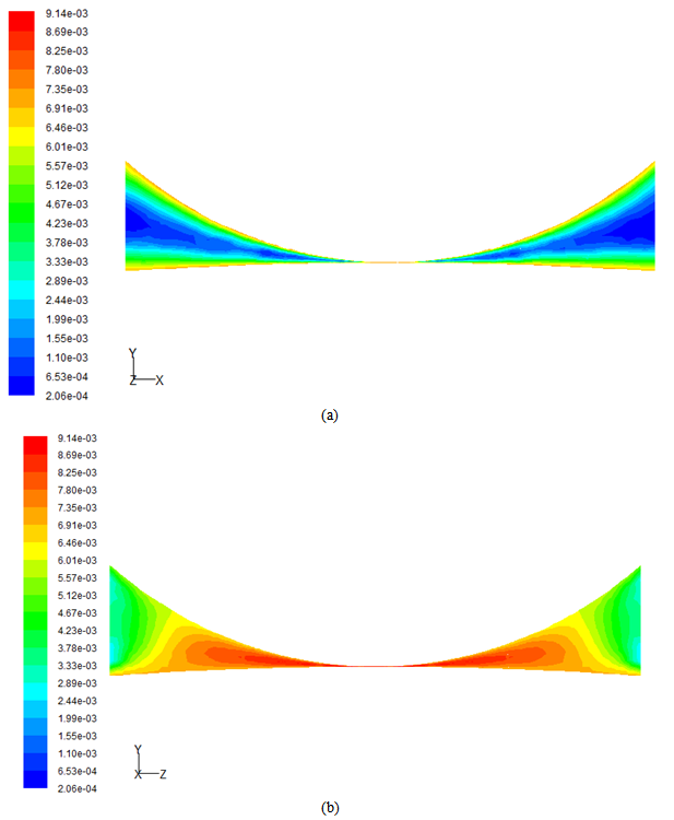 | Figure 7. The contour of the resulting speed (m/s) on the symmetry plane (a) and (b) perpendicular to it |
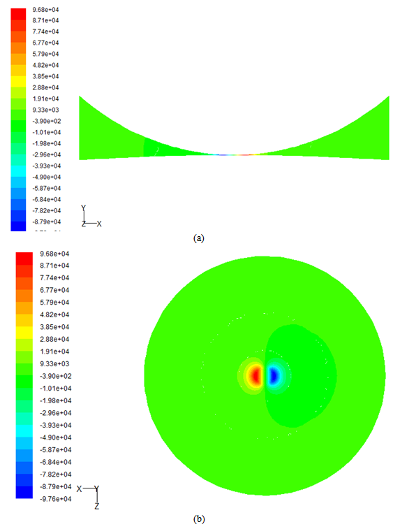 | Figure 8. The contour of the pressures (Pa) on the symmetry plane (a) and (b) on the wall of the ball |
 | Figure 9. Variation of minimum and maximum pressure (Pa) in the contact area |
As in the case of considering the undeformed geometry, the pressures distribution in the contact area is approximately symmetric, leading to a cancellation of the pressure effects. It is noted that for the ball sliding on the head, the maximum gauge pressure has the lowest value for all studied cases. Along with the angular speed increasing, the pressure gauge increases, the highest value being achieved for the case of the ball rolling without slipping over the head.
3.3. Variant III
3.3.1. Modeling the Joint Assembly
In the modeling it is considered the joint space consisting of fixed and movable walls. The movable wall that strikes the movement to the entire assembly is the head. As in the cases previous studied, six cases are considered: angular speed of the head has the values 0.5; 1; 1.5; 2; 2.5; 3 rad/s, angular speed vector is oriented along the Ox axis, in the positive sense.Figure 10 show he meshes with tetrahedral elements (a) and (b) a detail of the queue. Balls, located between the head and the cup, are driven in rotational motion by articular head, rotating around some axes that depend on the position of the balls and the intensity of contact forces between them. Considering that the intensity of the contact force between the balls is larger with the adjacent ball located to the basis of the head, the rotation axis of the ball is established on the direction of the center and the contact point with the neighbor ball, the closest to the head. Thus, the ball rotates around this direction, being actuated by the head. The angular speed of the ball is measured as in the 1st variant of computing.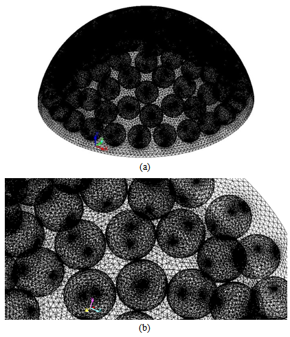 | Figure 10. The meshes with tetrahedral elements (a) and (b) a detail of the queue |
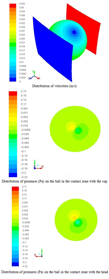
Also for conciseness, in Figs. 11 and 12 we present only the records for the speed of 3 rad/sec. 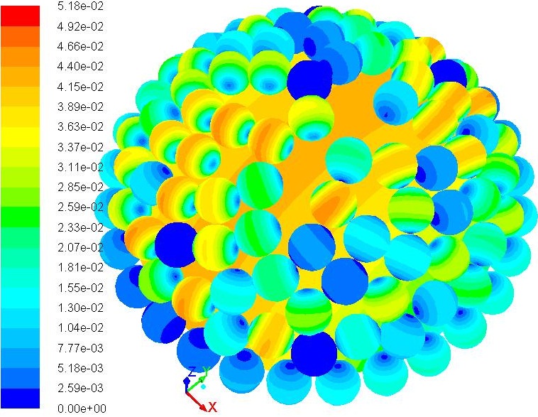 | Figure 11. Distribution of velocities (m/s) on the balls and head surfaces |
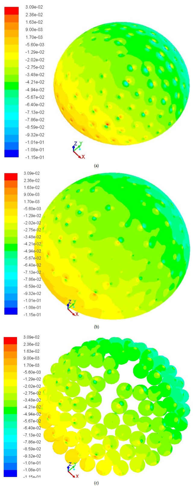 | Figure 12. Distribution of pressures (Pa) on the head (a), cup (b) and balls (c) |
3.3.2. Case 6 – Rotation Speed of the Head 3 rad/s
An increase of the pressure in the entire assembly in the direction of the angular speed of the head is observed, due to fluid actuation to that area by the rotation movement of the head and a decrease of the pressure in the opposite direction, decrease due to the same aspect - the fluid is "off" from this area by the rotation movement of the head.Considering that the natural joint, femoral head - acetabular cup is closed in the synovial capsule which secrete the sinovial fluid, an excess pressure certainly appears. In the literature there are not data reported about its value. In this situation, it was taken into consideration in the first instance, an excess pressure of 0.1 MPa, increasing in steps of 0.01 MPa, up to the value of 0.14 MPa.To represent the variation of pressure in contact areas between the ball, femoral head and the cup (Fig. 13), two surfaces with a width of 0.2 mm were defined, placed in the yOz plane (Oz axis passing through the centre of the head, the contact point between the head and the ball, the centre ball and point of contact between the ball and the cup). The variations in pressure on these areas will be represented according to the variable y. The contact area between the head and the ball and that of cup and ball is characterized by y = 0.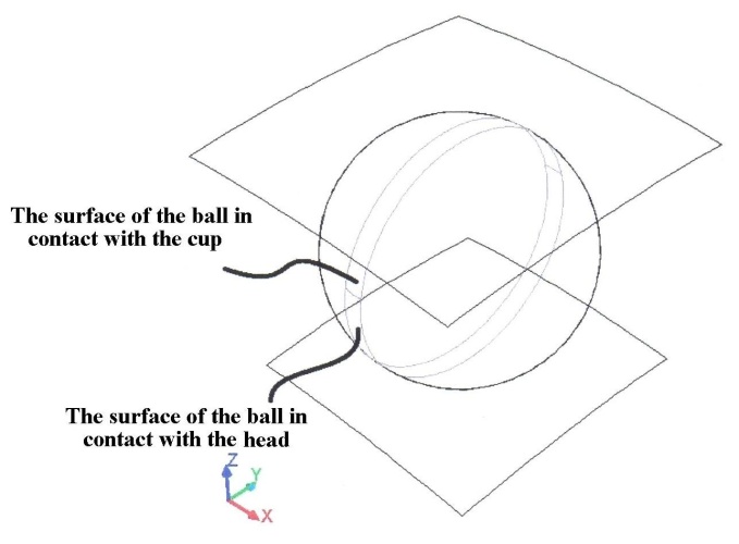 | Figure 13. Definiteness of areas taken into account |
They studied two cases: the case of newtonian fluid considered, in which the viscosity is constant, and the nenewtonian fluid case, where the viscosity depends on the speed (Fig. 14).Also, on the side surfaces of the fluid domain is considered a known pressure owing to a pressure of 0.11 MPa to 0.14 MPa, with a step of 0.01 MPa.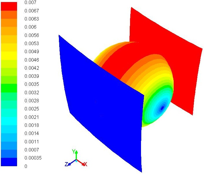 | Figure 14. The speeds at the walls distribution for all cases considered |
3.4. Newtonian Fluid with Constant Viscosity
The fluid had the density of 1118 kg/m3 and 0.8 kg/ms viscosity. a. 0.11 MPa pressure (Fig. 15)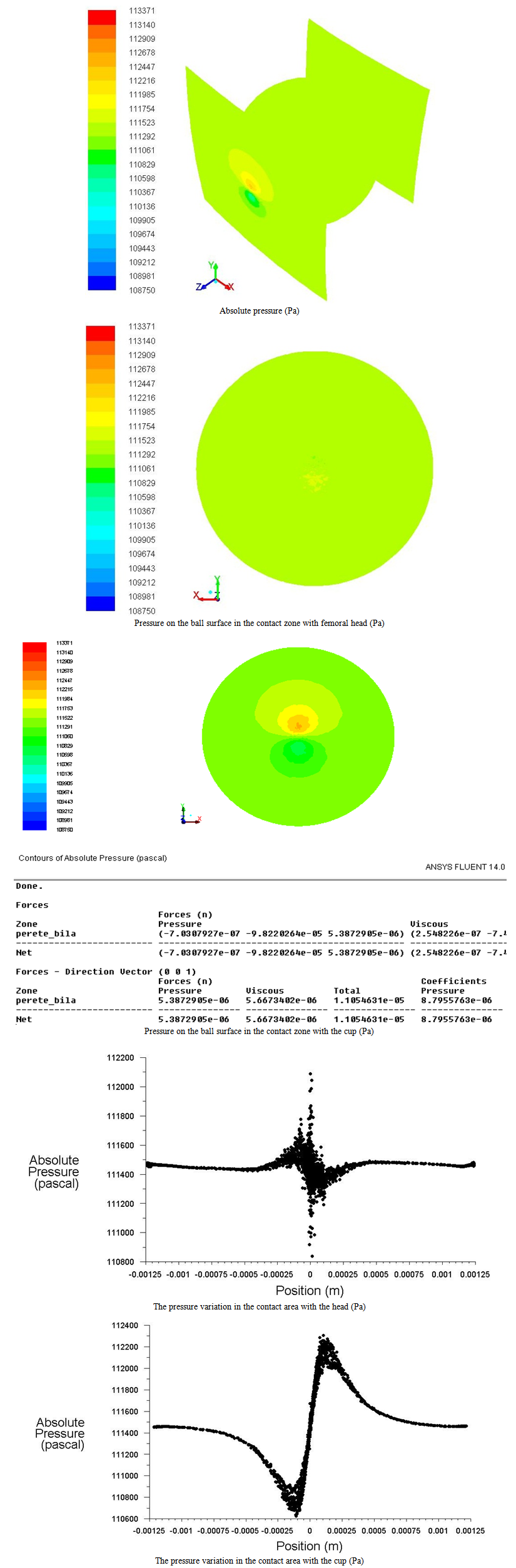 | Figure 15. Pressures and their variations in contact with the head and the cup at 0.11 MPa |
b. 0.12 MPa pressure (Fig. 16)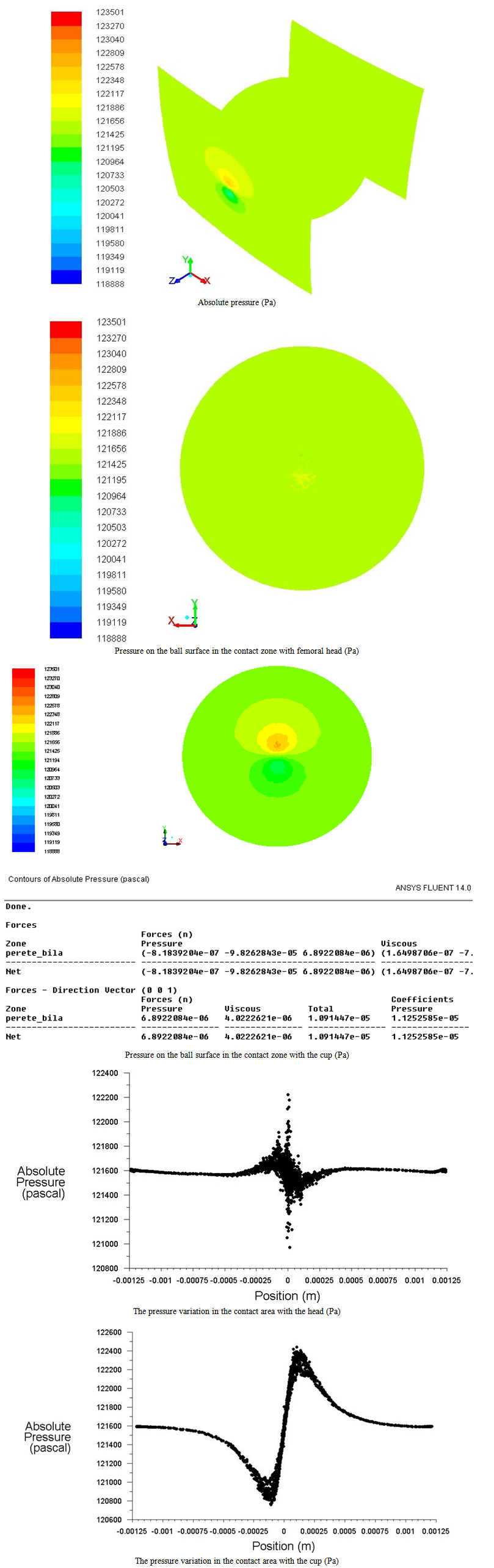 | Figure 16. Pressures and their variations in contact with the head and the cup at 0.12 MPa |
c. 0.13 MPa pressure (Fig. 17)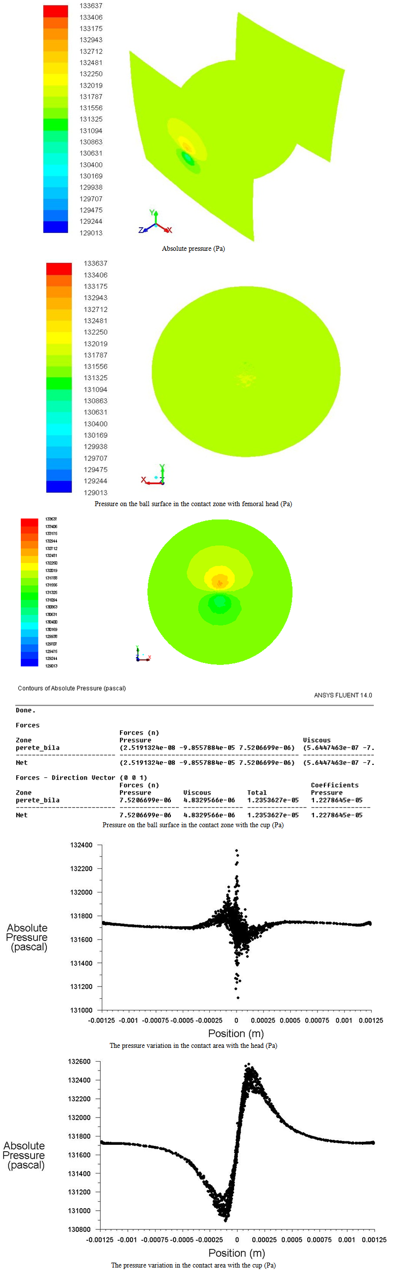 | Figure 17. Pressures and their variations in contact with the head and the cup at 0.13 MPa |
d. 0.14 MPa pressure (Fig. 18)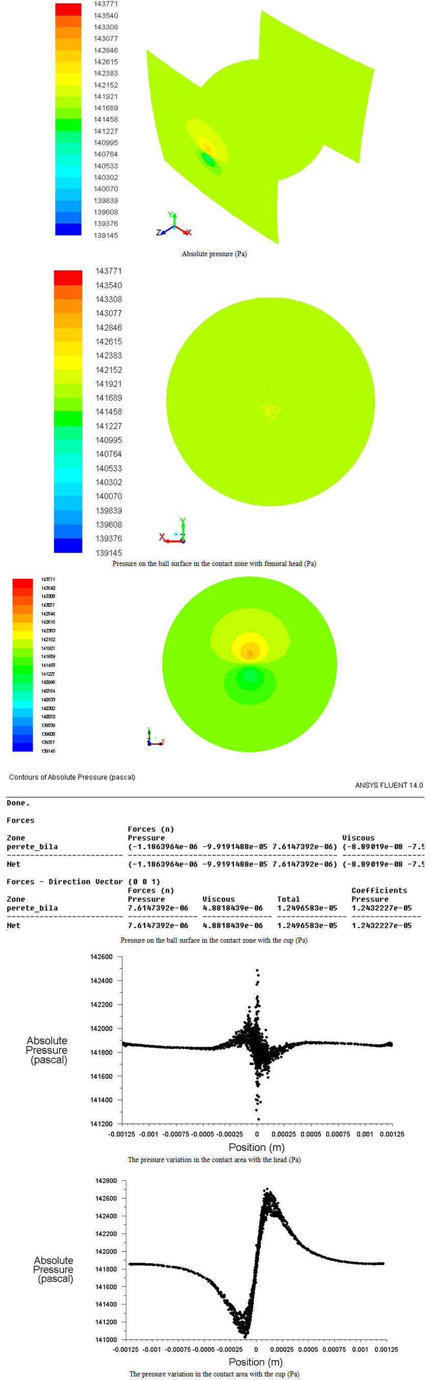 | Figure 18. Pressures and their variations in contact with the head and the cup at 0.14 MPa |
3.5. Nenewtonian Fluid with Variable Viscosity Based on Speed
The viscosity of synovial fluid is directly proportional to the concentration of hyaluronic acid content (Fig. 19).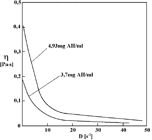 | Figure 19. Viscosity variation according to the gradient of velocity and hyaluronic acid concentration |
The law of viscosity variation is considered to be of power type, of the form | (8) |
where k - is a measure of the viscosity average (consistent index); n - is a measure of deviation to the newtonian fluid (the law index), being equal to 1 for newtonian fluid; H(T) – is a function that takes into account the influence of temperature on viscosity. In this case the viscosity is lower and upper bounded. For the calculations a concentration of 4.83 mg AH/ml was considered, where k = 0.7; n = 0.2; hmax = 0.5 μm and hmin = 0.008 μm.Were considered the same situations as the newtonian fluid.a. 0.11 MPa pressure (Fig. 20)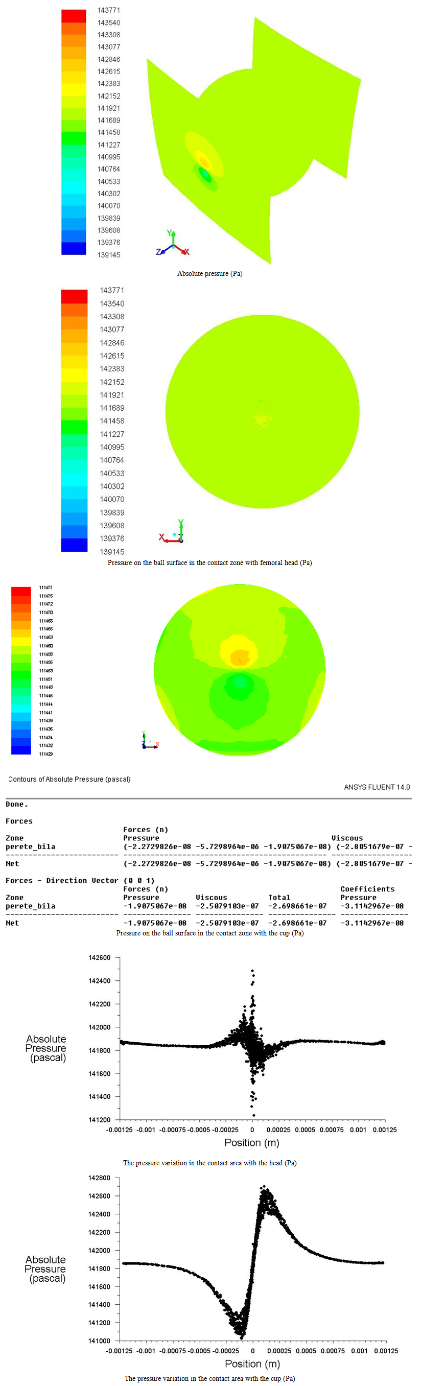 | Figure 20. Pressures and their variations in contact with the head and the cup at 0.11 MPa |
b. 0.12 MPa pressure (Fig. 21)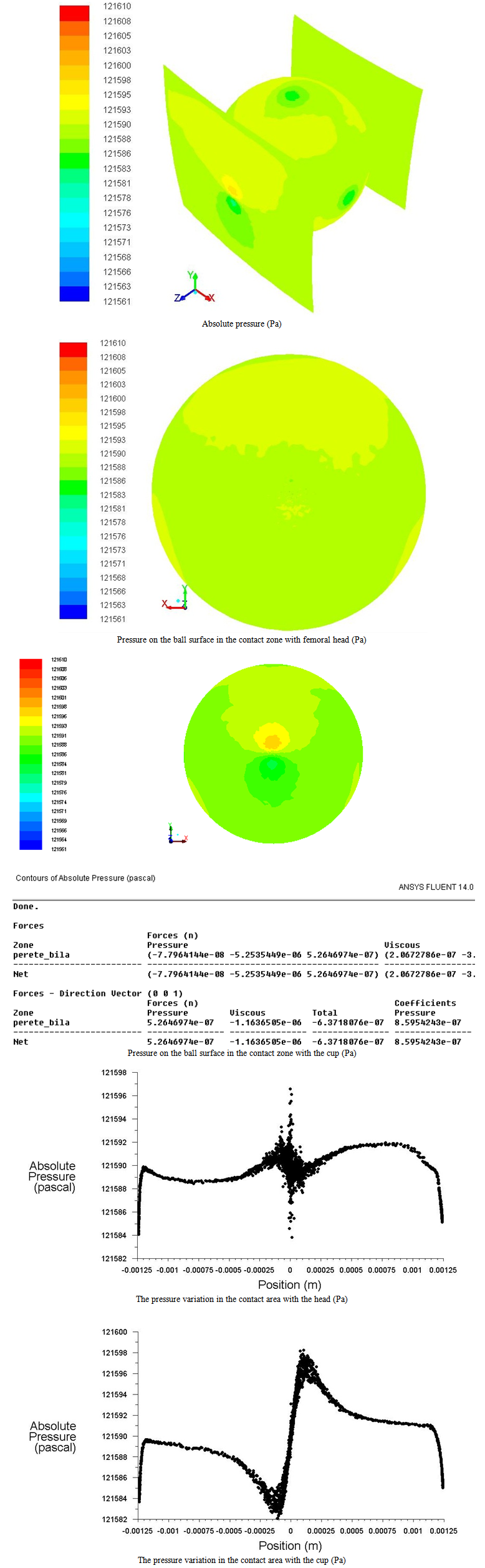 | Figure 21. Pressures and their variations in contact with the head and the cup at 0.12 MPa |
c. 0.13 MPa pressure (Fig. 22)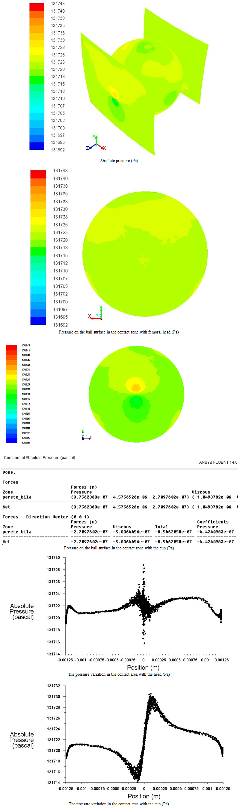 | Figure 22. Pressures and their variations in contact with the head and the cup at 0.13 MPa |
d. 0.14 MPa pressure (Fig. 23)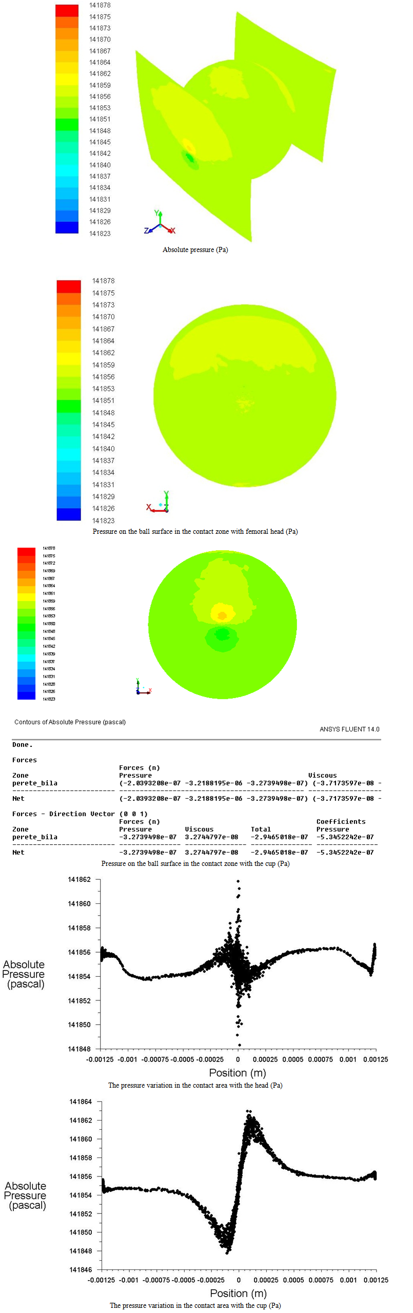 | Figure 23. Pressures and their variations in contact with the head and the cup at 0.14 MPa |
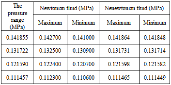
It is found, in all situations studied, a symmetrical distribution of pressure over the geometric focal point, both in the area of contact between the head and the ball, and in the contact zone between the cup and ball, leading to low values of the hydrodynamic forces.From the analysis of contact pressures in the contact areas (Tab. 1 and 2), it is observed that the maximum pressures when the fluid is considered newtonian, with constant viscosity, are higher than the values determined for the fluid considered nenewtonian.In terms of the minimum amount of pressure, it is remarked that the minimum values when the fluid is nenewtonian are greater than those determined in the case of newtonian fluid.From the analysis of the pressure in the contact areas can be observed that the maximum pressures when the fluid is newtonian considered, with a constant viscosity, are higher than the values determined for the fluid considered nenewtonian. In terms of the minimum amount of pressure, it is remarked that the minimum values when the fluid is nenewtonian are greater than those determined in the case of newtonian fluid.Observe the differences in pressure distribution of motion plane (yOz) in the two areas of contact. Thus, although both points are seen rolling without slipping, is a lower level of pressure in the contact area between the head and the ball (where the centers of the spheres is apart of the tangent plane) relative to the area of contact between the ball and the cup (where the centers of the spheres are of the same side of the tangent plane). The minimum thickness of the lubricating film in case the pressure of 0.14 MPa was found as 0.045 µm (Fig. 23), smaller than in case of using the method of contact resistance in the lab tests ball on flat (0.06 μm)[14].Table 1. The maximum and minimum pressures in the area of contact with the cup
 |
| |
|
Table 2. The maximum and minimum pressures in the area of contact with the femoral head
 |
| |
|
4. Conclusions
Total hip prosthesis with the balls in self-directed movement may be a viable solution for the durability increasing of of total hip replacements. The results obtained in experimental conditions of this study, showed that in the case of consideration of the lubricant used (Body Fluid Serum BSF) as a newtonian fluid were obtained pressures in contact area of the acetabular cup / ball / femoral head, more larger than for his consideration as a non-newtonian fluid.Lubricant film exist, but is torn because of the oscillating movement (300) in which the prosthesis it was tested, when ends of trace speed reaches the zero value. In these positions, contact pressure change their meaning (Figs. 20-23), causing seizure tendencies.The maximum contact pressure with the lubricant used, was higher on the femoral head (0.142500 - 0.112100 MPa) and less on the acetabular cup (0.141848 - 0.111449 MPa), probably due to the difference of distance from the center of the femoral head.This study has some limitations that should be taken into account in future research.The main limitation is the condition of movement used. Testing is required in terms of continuous motion, which virtually eliminate zero speed points, from switching the direction of movement.Another limitation is the duration of the calculation in Fluent, which imposed taking into account to a limited number of balls, as well as to neglect some of the contacts between the balls. Also another limitation lies in the uncertainty of the rheological nature or non- rheological of lubricating fluid properties.Is in progress an experimental device with two total hip prostheses in anatomical position mounted, whose movement to reproduce the flexion - extension movement of the of human hip joint. It is intended to continue the tribological research on total hip prosthesis with the balls in self directed motion.
ACKNOWLEDGEMENTS
The authors would like to thank Associate Professor Amado Stefan from the Technical Military Academy of Bucharest, for their scientific and logistic support in fluid mechanics study. We'd also like to thank the Romanian Academy for the logistic support offered in the production of this paper.
References
| [1] | Dowson D. Elastohydrodynamic lubrication.Interdisciplinary approach to the lubrication of concentrated contacts. (Ed. P.P.KU) NASA SP – 237 (1970). |
| [2] | Gao L., Wang F., Yang P., Jin Z. Effect of 3D physiological loading and motion on elastohydrodynamic lubrication of metal-on-metal total hip replacements. Medical Engineering & Physics 31 (2009) 720-729. |
| [3] | GAO L., WANG F., YANGP., JIN Z. Effect of 3D physiological loading and motion on elastohydrodynamic lubrication of metal-on-metal total hip replacements. Medical Engineering & Physics 31 (2009) 720-729. |
| [4] | MENG Q., GAO L., LIU F.,YANG P., FISHER J., JIN Z. Contact mechanics and elastohydrodynamic lubrication in a novel metal-on-metal hip implant with an aspherical bearing surface. Journal of Biomechanics 43 (2010) 849-857. |
| [5] | POURZAL R., THEISSMANN R., MORLOCK M., FISCHER A.. Micro-structural alterations within different areas of articulating surfaces of a metal-on-metal hip resurfacing system. Wear 267 (2009) 689-694. |
| [6] | YANA Y., NEVILLE A., DOWSON D., WILLIAMS S., FISHER J. The effect of nanoparticles on the behavior of the metal on metal total hip prosthesis biotribocorrosion. Wear 268 (2010) 683-688. |
| [7] | LI C.X., HUSSAIN A., KAMALI A. Consideration of non-bearing surface condition and its potential effect on hip wear simulation test results. Wear 268 (2010) 762-789. |
| [8] | OSTERLE W., KLAFFKE D., GRIEPENTROG M., GROSS U., KRANZ I., KNABE CH. Potential of wear resistant coatings on Ti–6Al–4V for artificial hip joint bearing. Wear 264 (2008) 505-517. |
| [9] | KATSUOSHI B., KIYOSHI S. US Patent 5092898 / 03.03.1992. |
| [10] | J.P. DAVANT J.P. Chirurgie de la hance. Mieux vivre avec une prosthesis. Fonder l’Avenir, 23, pp. 53-56, 1995. |
| [11] | SADEGHI-MEHR M. Investigations of Rolling Element Bearing for Hip Joint Prosthesis, PhD Thesis, Imperial College of Science, Technology and Medicine University. London, 1997. |
| [12] | IAROVICI A, CAPITANU L., FLORESCU V., BAUBEC M. Hip Joint Prosthesis with Rolling Bodies. Proceedings of the Romanian Academy – Series A: Mathematics and Physics, Technical Sciences, Information Science, 1, 1-2, pp. 37-44, S. 2001. |
| [13] | CAPITANU L., FLORESCU V. New Concepts for Improved Durability in MOM Total Hip Endoprostheses. A review. American Journal of Materials Science. Vol.2, No. 6, December 2012. |
| [14] | CAPITANU L., BADITA L.L., FLORESCU V., BURSUC D.C. Preliminary Study on the Seizure Trend of a MOM-THP with Self-Directed Balls. Journal of Mechanics Engineering and Automation. Volume 3, Number 9, September 2013. |
| [15] | RUMSEY C. Turbulence Modeling Resource. NASA, Langley Research Center (2013). turbmodels.larc.nasa.gov/spalart.html. |
 Abstract
 Reference
 Full-Text PDF
 Full-text HTML