Masaru Naruoka
Flight Research Center, Japan Aerospace Exploration Agency, Mitaka, 181-0015, Japan
Correspondence to: Masaru Naruoka , Flight Research Center, Japan Aerospace Exploration Agency, Mitaka, 181-0015, Japan.
| Email: |  |
Copyright © 2012 Scientific & Academic Publishing. All Rights Reserved.
Abstract
Performance of system identification of aircraft flight characteristics quite depends on flight data to be analyzed.In order to make the system identification more useful and reliable, a real-time flight data evaluator which determines appropriate parts of data is proposed.The proposed method is characterized by multi resolution analysis (MRA), a kind of wavelet transform, and validates flight in both time and frequency domains.Results to apply the proposed methods to both simulated and real flight data show that the proposed method has adequate capability to extract desirable parts from flight data.
Keywords:
System Identification, Wavelet Transform, Trim Flight, Multi Resolution Analysis
Cite this paper: Masaru Naruoka , Real-time Wavelet Flight Data Evaluator for System Identification of Flight Characteristics, Journal of Mechanical Engineering and Automation, Vol. 3 No. 1, 2013, pp. 8-15. doi: 10.5923/j.jmea.20130301.02.
1. Introduction
Flight tests are important tasks to develop new aircraft.This is because design, production and operation steps are seamlessly connected with the flight tests.Especially, system identification which estimates flight characteristics with flight data obtained by the tests is requisite.The estimated flight characteristics are used for comparisons with wind tunnel test results.If a critical difference is revealed in these comparisons, aircraft must be corrected until the difference is reasonable.Moreover, handling quality checks[1] requested for airworthiness certification, and making a flight simulator for pilot training are also performed with the system identification results.In addition to the essential roles of the system identification mentioned above, its utilization to improve flight safety is considerable.The system identification generates mathematical models which are composed of parameters to describe flight characteristics.This means whenever the system identification is performed in flight, flight characteristics are monitored quantitatively in real-time.Therefore, sudden changes of the parameters derived from an accident can be captured by the system identification, and will be utilized for pilot or autopilot system to recover from critical situations.However, the system identification is not applicable easily, because accuracy of its results mostly depends on flight conditions. For example, if there is strong gust, parameters estimated by the system identification will be quite differentfrom wind tunnel test results.Maneuvering is also an important factor to obtain probable results, because the system identification requires adequate excitation of motion in terms of magnitude and frequency.Furthermore, appropriate parts in which the required flight conditions are satisfied have been selected manually, and there is no intelligent method to extract these parts from flight data automatically.In order to make the system identification more useful and reliable, an intelligent flight data evaluator, which automatically determines whether flight data can be used for the system identification, is required. In addition, if the evaluator works concurrently with flight, we can extend applications of the system identification, such as the flight characteristics monitoring.Therefore, a real-time flight data evaluator using wavelet transform is proposed.This paper consists of five sections. Section 2 provides general information of the system identification of aircraft flight characteristics, and defines appropriate flight which is suitable for the system identification.In Sec. 3 the proposed method characterized by wavelet transform is explained and preliminary tests of the proposed method are referred.Then, experimental results obtained by applying the proposed method to real flight data are described and effectiveness of the proposed method is discussed in Sec. 4.Finally, this study is concluded in Sec. 5.
2. Appropriate Flight for System Identification
In this section, general procedures of the system identification of flight characteristics are introduced. Through this introduction, requirements for flight data to perform the identification effectively are summarized.The typical appropriate flight satisfying the requirements is also explained.
2.1. Aircraft System Identification
The system identification is mostly utilized for estimation of quantitative flight characteristics, while pilot comments are used for acquisition of qualitative ones.In other words, the system identification of flight characteristics is almost equivalent to parameter estimation.This is because the quantitative characteristics are frequently indicated by parameters of a predefined model, for example, coefficients of transfer functions, gains and phase shifts of frequency responses, and stability derivatives consisting of equations of motion.Each predefined model reflects knowledge of flight dynamics of aircraft, and most of them are depicted with a certain base state and deflections from the base state.For later explanation, an example predefined model will be referred.The following equation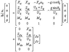 | (1) |
is the well-known linearized perturbation equation of longitudinal motion of fixed wing aircraft [2], where symbols X, Z, M are longitudinal stability derivatives to be estimated. u, α, q, θare state values, that is, wind speed deflection, angle of attack, pitch rate, and pitch angle deflection, respectively. δe, δt are inputs, that is, deflections of elevator and thrust maneuvering. t is time, and g is gravity. U0, θ0are wind speed and pitch angle of a trimmed state.
2.2. Appropriate Flight
Appropriate flight data, which contains sufficient information to make estimation of parameters reliable and accurate as possible, must cover flight envelop assumed in the predefined model.Especially, to acquire the certain base state accurately assumed in the predefined model like shown in U0and θ0 of Eq. (1) is important.For easiness of realization of the basic state in flight, the basic state is frequently chosen from trimmed states, in which no maneuvering is required to maintain flight.This is based on a fact that most of aircraft are designed to have both static and dynamical stability, that is, aircraft will be recovered to a trimmed state if disturbance such as gust is occurred.If target aircraft originally has negative stability like fighters, this approach can be still available, because a total system will be stable by using a suitable feedback controller. In addition to the trimmed states, to obtain behaviour when inputs are added is also essential.In other words, intentional maneuvering which invokes both instantaneous and transient response adequately is required.To follow the above mentions, the appropriate flight, with which the system identification estimates flight characteristics accurately, consists of the following three phases like shown in Fig. 1.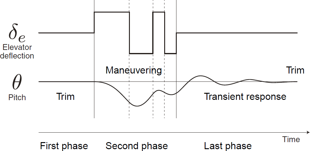 | Figure 1. Concept of appropriate flight for the systemidentification of flight characteristics |
In the first phase of Fig.1, stationary elevator and pitch angle, which are essential inputs and state values to analyze longitudinal motion, respectively, are indicated. Then, in the second phase, suitable maneuvering is performed to excite sufficient motion in terms of magnitude and frequency.As an example, a 3-2-1-1 multi-pulse elevator control pattern recommended by Marchand [3] is depicted in Fig.1.The pitch angle shown in Fig.1 is also changed in response to the maneuvering.The last phase is returning to the trimmed state through transient responses by stopping the maneuvering and then keeping control inputs at the same positions of the first phase.The last phase of the example shown in Fig.1 indicates that while the elevator deflection is zero, the pitch angle is still changed.For automatic flight data evaluation, the above qualitative conditions must be represented quantitatively.Especially, how small changes of the significant state values in the first phase are permitted must be carefully arranged.This is because the second and last phases are evaluated with the deflections from the first phase, which is assumed to be adequately trimmed.Furthermore, to evaluate flight in real-time, it is preferable that required computational power is small.The proposed method explained in the next section considers these problems.
3. Method
The proposed method, which determines the appropriate flight for the system identification, is characterized by MRA, an implementation of wavelet transform.In this section, fundamental information of wavelet transform and MRA will be provided, and then, the proposed method is explained.
3.1. Wavelet Transform and MRA
Generally, wavelet transform decomposes a time variant function into time-frequency information in the following equation: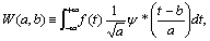 | (2) |
wheret is time, and a and b are called scale and shift parameters, which correspond to frequency band and time, respectively. is a mother wavelet function, which is well arranged to express localized oscillation.Equation (2) means that the transform is performed by measuring correlation between the function and a template generated with the mother wavelet function.This implies square of a wavelet transform value
  corresponds to signal strength at certain frequency band and time.In this study, multi resolution analysis (MRA) [4] is utilized.MRA is a specialized version of wavelet transform, and converts discrete time series data such as flight data into time-frequency information.Figure 2 shows time series data and MRA results of a linear up-chirp signal, in which frequency increases with time.The results show that frequency bands in which signal is strong go higher as time passes. This indicates that MRA is a powerful tool to analyze vibration of discrete data in terms of both time and frequency.
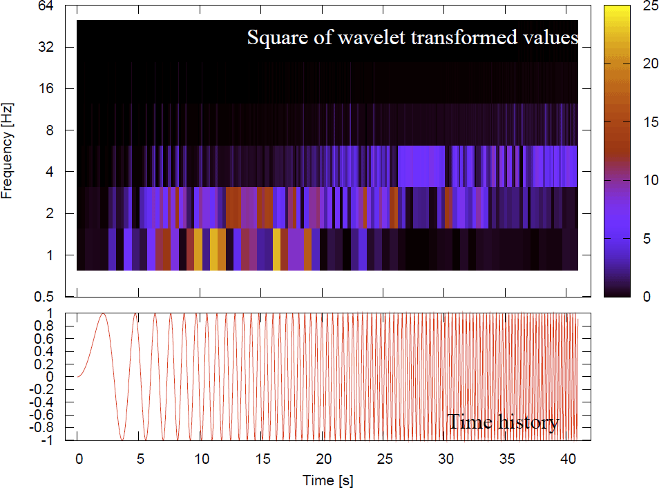 | Figure 2. Time history of a linear chirp signal (bottom)and its MRA results (top). The MRA resultsare shown with square of transformed values correlatedto signal strength |
Another MRA suitability for this study is its efficiency of the transform.Figure 3 is a conceptual timing chart showing when MRA transform results are available.The higher frequency band information of the MRA results is updated more frequently than the lower frequency band.This is quite different from short-time Fourier transform (SFT).SFT is another sophisticated tool to calculate time-frequency information,however, its transform results are obtained after all target time series data are processed regardless of frequency bands.Moreover, MRA requires  arithmetical operations while SFT with the lowest computational implementation using fast Fourier transform (FFT) is
 [5], where N is sample number of target data.Therefore, MRA is superior to SFT for the real-time evaluation of this study in terms of both data instantaneousness and computational cost.
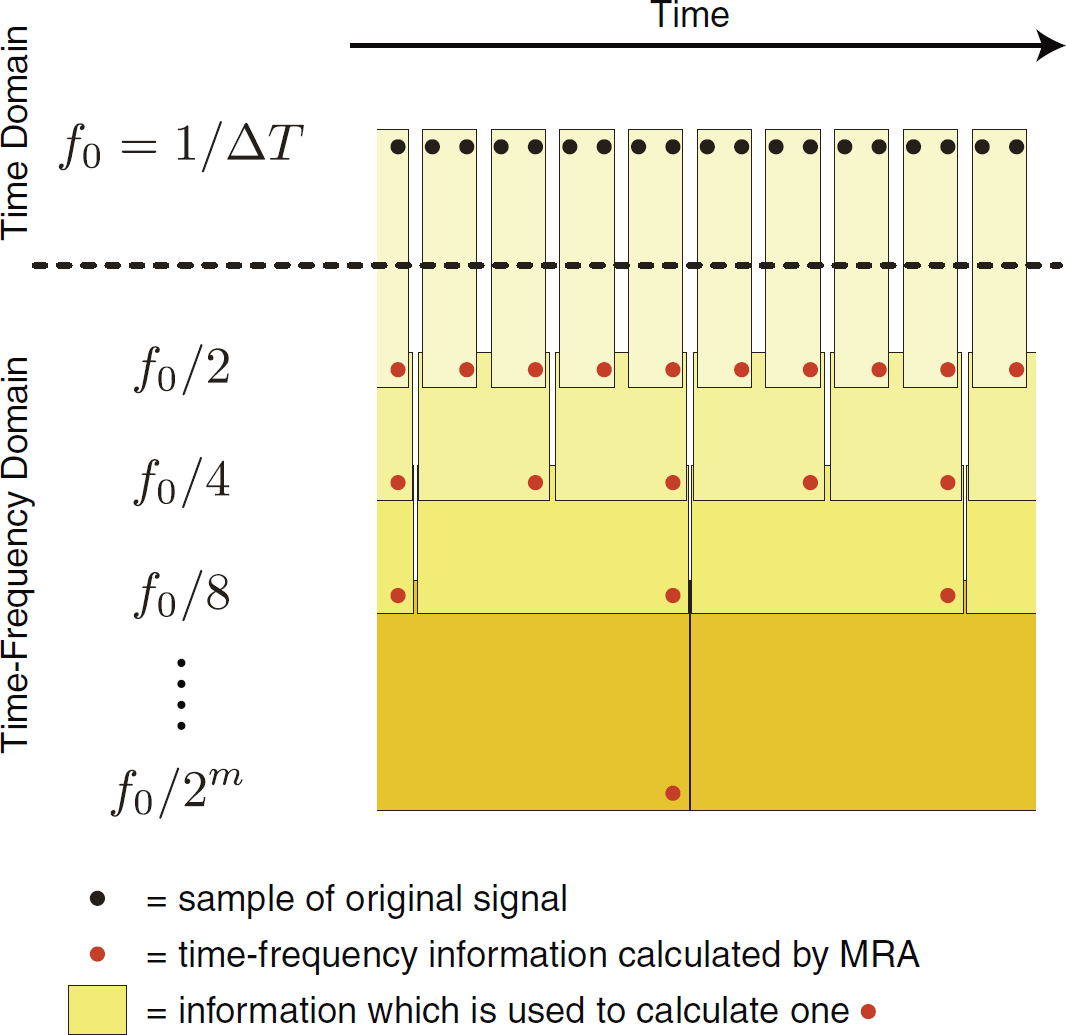 | Figure 3. Conceptual timing chart of MRAcalculation |
It is noted that choice of the mother wavelet function is still important when MRA is utilized.Including the chirp example shown in Fig. 2, this study utilizes Daubeches wavelet [6].
3.2. Proposed Method
The proposed method analyzes vibration of flight with signal strength obtained by MRA, and determines whether the requirements of the appropriate flight depicted in Sec.2.2 are satisfied.In the following, the separation rules of the method are summarized based on the three phases shown in Fig.1.The appropriate flight in the first phase, in which the adequate trim flight is supposed, is represented with wavelet transform values as: | (3) |
 | (4) |
wherezx and zu are observed values correlated with state values x and inputs u, respectively.There are two parameters Δ and a*, which should be configured appropriately.a* is certain frequency bands in which measurement noise is comparatively weak, namely, aircraft motion and maneuvering are sufficiently observable. Δ represents a threshold to determine whether data is not changed and almost settled.The requirements in the second phase are described in the following equations: | (5) |
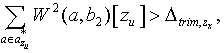 | (6) |
These two equations mean that strong correlation between aircraft motion and maneuvering is assumed, and maneuvering is intentionally strong enough.The last phase satisfies | (7) |
 | (8) |
where observed values of state values zx are gradually converged to the initial trimmed state, while observed values of inputs zu are stationary.
3.3. Preliminary Tests
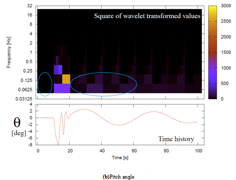
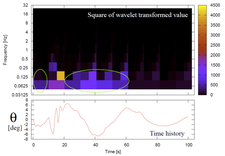
The proposed method is preliminary examined with simulation data generated with the longitudinal equation of motion represented by Eq. (1).As the stability derivatives of Eq. (1), those of P2V-7 variable flight characteristic research aircraft [7] are used.In the simulation, elevator inputs are identical to Fig. 1, namely, trimmed, then 3-2-1-1 from the trimmed position, and finally trimmed, while thrust is always fixed at its trimmed value.Figure 4 shows an appropriate flight approved by the proposed method.The elevator deflection δe and pitch angle θ time histories are represented, and their signal strength obtained by MRA are also indicated by color, same as the chirp example shown in Fig. 2.Figure 5 depicts another pitch angle θtime histories, where strong disturbance which must be avoided for the appropriate flight is introduced besides the same elevator deflection as Fig. 4.In the green circled areas in Fig. 5, the signal strength is stronger than those of their corresponding parts of the appropriate flight, which are surrounded by the cyan circles in Fig. 4.These differences can be used for the rules of Eqs. (3)-(8).Therefore, the preliminary tests reveal that the proposed method has basic capability to evaluate flight.
4. Application to Real FlightData
The proposed method is evaluated with application to real flight data.The analyzed flight data is so massive that the proposed method adequately demonstrates its convenience. In this section, the method and results of this evaluation are explained.
4.1. Evaluation Method
The real flight data to which the proposed method is applied is obtained by experimental aircraft MuPAL-α [8] developed by Japan Aerospace Exploration Agency (JAXA).MuPAL-α is modified by adding various measurement devices and fly-by-wire control mechanism to fixed-wing turbo-prop aircraft Dornier Do228-202. A model of the flight characteristics of MuPAL-α has been already established accurately by using results of wind tunnel and flight tests.For the evaluation, its 271 hours data of 173 flights from year 2000 to 2011 is used.By applying the proposed method, its trim flight is extracted by usingEqs. (3)-(4).Comparing state values in the extracted trim flight with the known characteristics, the proposed method is evaluated.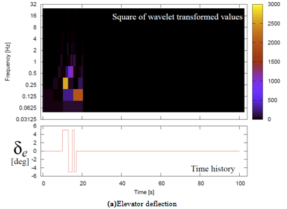 | Figure 4a. Elevator deflection and pitch angle of appropriateflight data |
 | Figure 4b. Elevator deflection and pitch angle of appropriateflight data |
 | Figure 5. Pitch angle of not appropriate flight data |
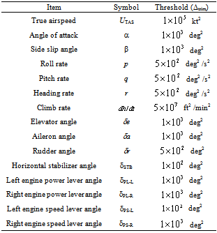
The flight data obtained with MuPAL-α consists of state values and inputs such as angle of attack, wind speed, pitch angle, pitch rate, and elevator angle.The data is sampled at 50 Hz, that is, the time interval of the discretized data is 0.02 seconds.a* of Eqs. (3)-(4) is fixed with frequency bands ranging from 10 Hz to approximate 0.05 Hz, which equals to the inverse number of time interval of 1024 samples.The reason why a* is not ranged from 50 Hz of the sampling rate is to suppress the measurement noise.Table 1 lists thresholds with which the trimmed states are determined by the proposed method.These thresholds are configured based on manual extractions of the trim flight beforehand with this evaluation.Table 1. Thresholds for Determination of the Trimmed States
 |
| |
|
4.2. Results and Discussions
The proposed method determines 12013 cases of 69.6 hours as the trimmed states, and some significant results of the extracted trim will be described.Figures 6-7 show relations between true airspeed and angle of attack, and relations between horizontal stabilizer angle and angle of attack, respectively.These relations are sorted by flap positions and color coded in the figures.Calculated relations by using the established flight characteristics model are also depicted with the lines.The extracted and calculated relations at the trimmed states are well agreed.This means that the proposed method has capability to extract the preferable flight even in the case of real flight.The agreements between the extracted and calculated relations will be improved with further consideration of flight condition differences.Figures 8-9 show the relations corresponding to Fig. 6 with the calculated results under different flight altitude and aircraft weight, respectively.These figures indicate that different flight conditions result in different trimmed states.Therefore, it is important to configure the parameters of the proposed method represented by Table 1 in order to extract the desired parts from flight more accurately.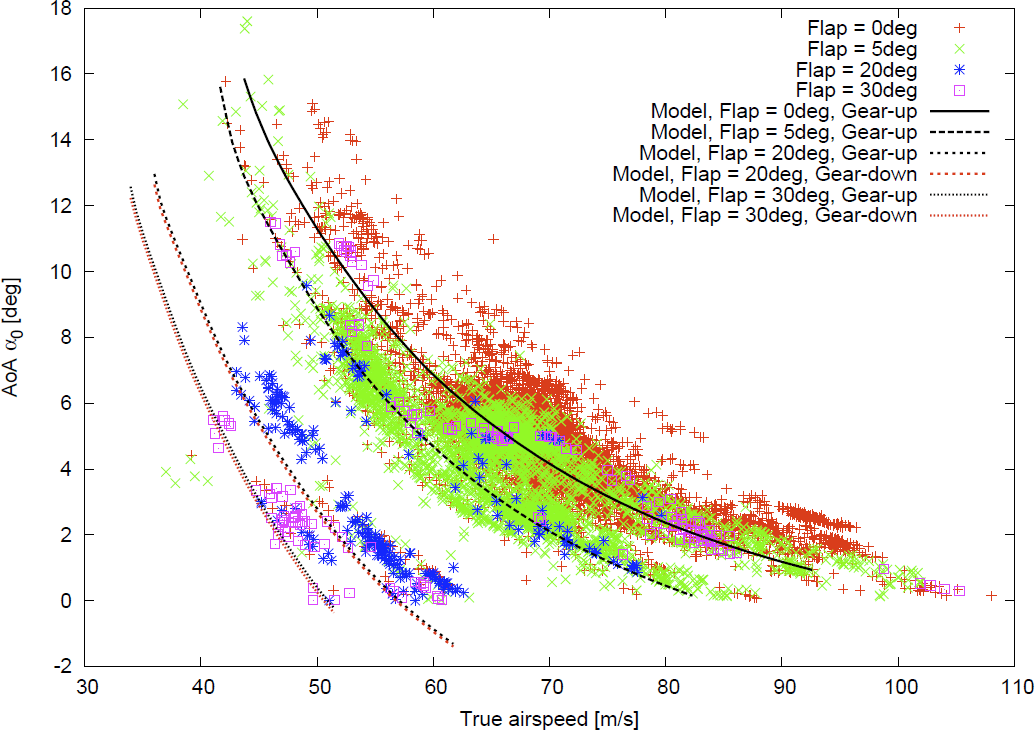 | Figure 6. True airspeed and angle of attack at the trimmed states of real flight and model |
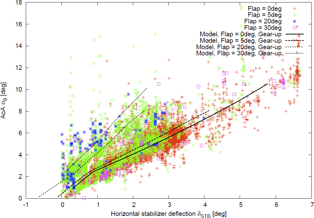 | Figure 7. Horizontal stabilizer angle and angle of attack at the trimmed states of real flight and model |
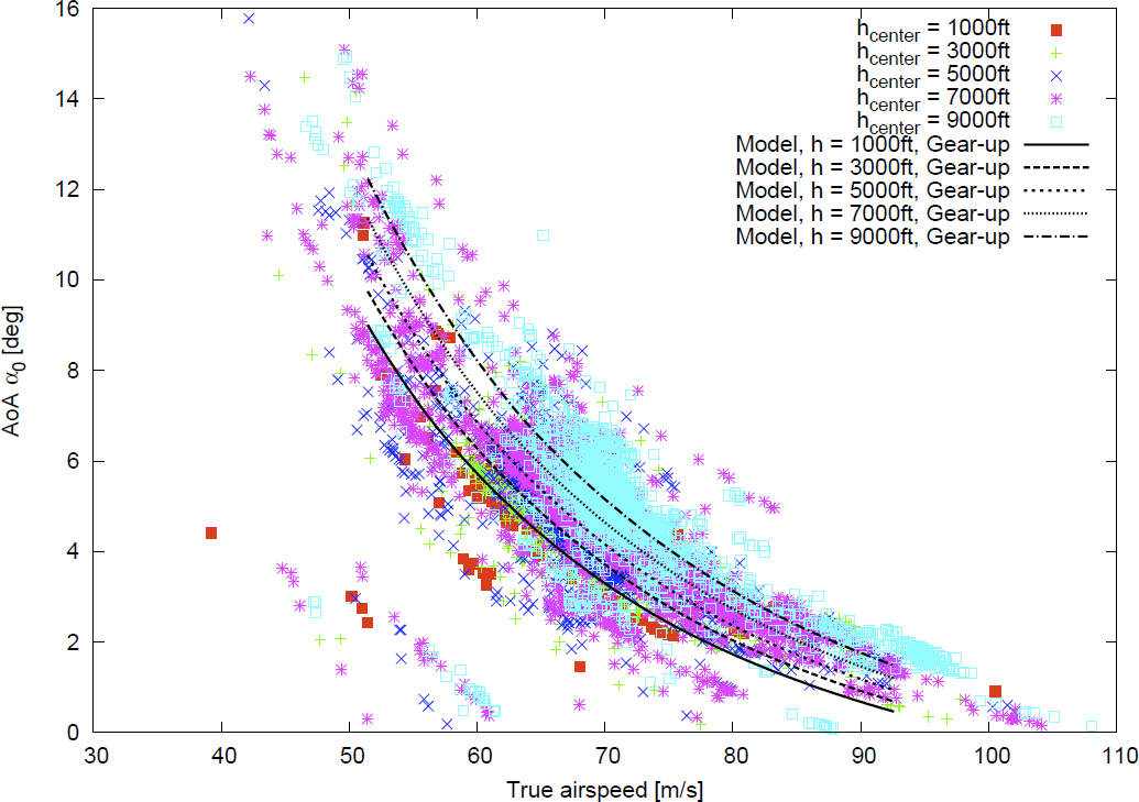 | Figure 8. True airspeed and angle of attack at the trimmed states of real flight and model under 0 degree flap position and different altitude |
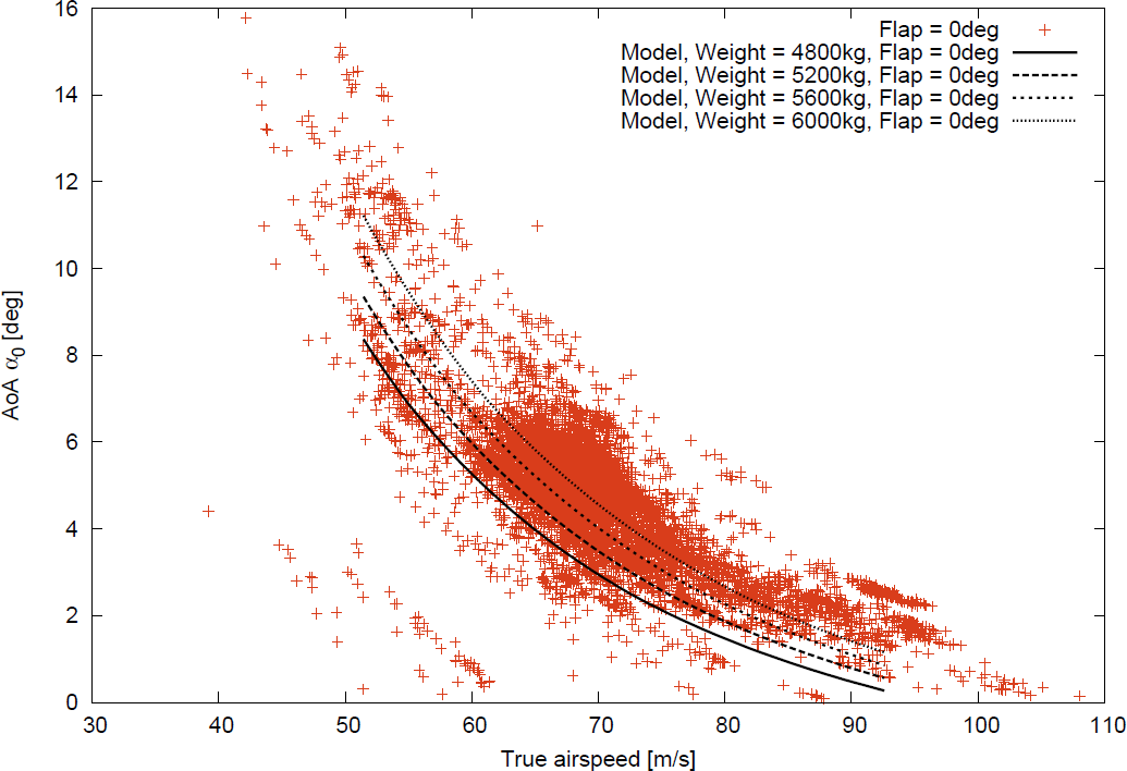 | Figure 9. True airspeed and angle of attack at the trimmed states of real flight and model under 0 degree flap position and different weight |
5. Conclusions
In this study, the new real-time flight data evaluator which determines the appropriate parts for the system identification of aircraft flight characteristics was proposed.The proposed method utilizes MRA, which is an advantageous implementation of wavelet transform in terms of computational cost and instantaneousness, to calculate values corresponding to signal strength in time-frequency domain.By comparisons with the carefully arranged thresholds and the calculated values, the trim, intentional maneuvering, and transient response phases are promptly extracted in flight as the appropriate parts for the system identification.The preliminary tests with simulated flight data indicated that the MRA calculated values were different between the desirable and undesirable cases, and the concept of the proposed method was reasonable.Furthermore, the proposed method was applicable to the real flight data.This was demonstrated by the proposed method extracting the trim flight from the massive real flight data.Therefore, it was concluded that the proposed method effectively evaluated flight and could extract the appropriate flight for the system identification of aircraft flight characteristics.
References
| [1] | Flying qualities of piloted vehicles, MIL Std. 1797A, 1990. |
| [2] | K. Kato, A. Ohya,K.Karasawa, Primer ofAircraft Dynamics, University ofTokyo Press, Japan, 1982. (in Japanese) |
| [3] | M. Marchand,R. Koehler,“Determinationof aircraft derivatives by automatic parameteradjustment and frequency response methods”, AGARD, CP 172, Paper No 17, 1974. |
| [4] | J. W. Cooley, J. W. Tukey, “An algorithm for the machine calculation of complex Fourier series”, Math. Comput. 19 (90): pp.297–301, 1965. |
| [5] | S.Mallat, “A theory for multiresolution signal decomposition: the wavelet representation”, IEEE Transactions on Pattern Recognition and Machine Intelligence 11 (7): pp.674-693, 1989. |
| [6] | I.Daubechies, Ten lectures on wavelets, Societyfor Industrial and Applied Mathematics,USA, 1992. |
| [7] | K. Isozaki, K. Masuda, A.Taniuchi, T. Watari. “Flight tests and evaluation of varaiableflight characteristics reserach aircraft”, Kawasaki heavy industry technical report,Kawasaki Heavy Industry, 1980.(injapanese) |
| [8] | K. Masui,Y. Tsukano, "Development of a new in-flight simulatorMuPAL-α",Proc. AIAA Modeling and Simulation Technologies Conference and Exhibit, Denver, AIAA-2000-4574, 2000. |
 Abstract
 Reference
 Full-Text PDF
 Full-text HTML