Folushola O. Dolire , Tajudeen A. O. Salau
Department of Mechanical Engineering, University of Ibadan, Ibadan, Nigeria
Correspondence to: Folushola O. Dolire , Department of Mechanical Engineering, University of Ibadan, Ibadan, Nigeria.
| Email: |  |
Copyright © 2012 Scientific & Academic Publishing. All Rights Reserved.
Abstract
This work investigated the control of chaotic behavior of a harmonically perturbed Duffing Oscillator using vibration absorber. The systems of two degrees of freedom governing equations were simulated numerically using classical fourth order Runge-Kutta algorithm for a constant time step. The solution time history, phase plots and Poincare maps were used to validate the simulation. Essentially, the details of the Poincare map were used numerically to determine the periodicity of Duffing oscillator for spectrum of mass ratio at a constant step of 0.001. The time history, phase plots and the Poincare at mass ratio (µ), absorber parameters (αa), and amplitude of excitation (Fo) are in agreement with what is obtained in open literature. The chaotic response of the Duffing-Absorber system at αa = 1.1, Fo = 0.21; and, taken respectively, the Duffing and the absorber initial conditions to be (1.0, 0.0) and (0.0, 0.0), this chaotic response was rendered periodic for some selected mass ratio (0≤µ≤1.0). Specifically, periods 1, 2 and 4 were obtained at µ= 0.208; these periodic responses were obtained at respective values of αa=1.1, αa=1.7803 and αa= 1.7595. In this work, eighty percent of the mass ratio selected did ensure that the chaotic behaviour of the Duffing-Absorber system is rendered periodic. This work demonstrated the practical utility of vibration absorber as a chaotic oscillations control tool by the mass ratio approach; and having a recorded success of about eighty percent.
Keywords:
Duffing Oscillator, Mass Ratio, Constant Step, Chaotic Oscillations
Cite this paper: Folushola O. Dolire , Tajudeen A. O. Salau , Control of Chaotic Oscillation and Response Charaterisation in Duffing Oscillator Using Vibration Absorber, Journal of Mechanical Engineering and Automation, Vol. 3 No. 1, 2013, pp. 1-7. doi: 10.5923/j.jmea.20130301.01.
1. Introduction
The behaviour of systems under external perturbations has been subject of active research area in the past few centuries. Until recently the study of the behaviour of most dynamical systems has been restricted to linear systems due to the limitations of existing classical analytical tools to handle systems that are nonlinear with multi-degrees of freedom. Furthermore, the so-called numerical techniques to simulate these categories of systems are computationally laborious, so the human constraints are visible in this regard. Reprieve came our way with the advent of personal computers; these machines give room for extensive insight into how and why some completely deterministic dynamical system could behave so strange. As of now, the computer remains the only ‘reliable’ tool to study these categories of systems partly because of the resulting complex geometry and majorly due to the number of iterations required to home in on the solutions being sought – a concept referred to as experimental mathematics. The most fundamental and fascinating phenomenon in this behaviour is that exhibited by a classical simple pendulum having unusually large amplitude,[1]. The usual simplifying assumption imposed on a simple pendulum to linearize it has hidden its unique features for centuries. However, it is instructive to mention here that not all nonlinear equations can lead to period-doubling and possibly chaos, see[2]. The pendulum model is simple but produces an astonishingly complex geometry. If a dynamical system involves no stochastic variables in its mathematical formulations, then it should behave in a manner that will make predictability possible and the history of such a system can be known with certainty. But, this is never so. Reference[3] in1963 was baffled by the result of his weather experiment which later brought to the conclusion that some dynamical systems of interest could be unpredictable because of their nonlinear relations and their sensitivity to initial conditions[4]. This Lorenz model are a simplified version of the earlier work on atmospheric fluid dynamics carried out by Saltzman in 1962,[5]. Sensitivity to initial conditions is responsible for the seemingly unpredictable, long-term temporal evolution of aperiodic motion, and in fact a vanishingly small error in the measurement of the initial conditions of any real or deterministic dynamical system brings about loss of predictability of its long-term behavioural patterns. As we cannot measure any real dynamical system with infinite precision the long term prediction of chaotic motion in such systems is impossible, even if we know the equations that model the systems precisely, argued[6]. A small alteration in the system parameters could render the system chaotic. This chaotic behaviour is one of the ways in which nonlinear dynamical system manifests as written by[7]. Yet it is important that scientist and engineers be able to tell the future characteristic or response of a system whose mathematical model(s) are known. In the ordinary sense of things everybody wants to know what the future holds. So, the ideal of wanting to know what the future looks like is not limited to the technical people. The study of chaos has gained tremendous attention over the last few years. Control of chaotic oscillations by vibration absorber appendage based on some parameters of control has been reported by[8]. The duo through some numerical simulations obtained periodicity from a notoriously unpredictable system exhibiting strange attractor behaviour, but were not specific in their work what system parameter in the name mass-ratio that was used to gain control over the chaotic system. We express no doubt that the Duffing Oscillator behaves chaotically. In a study of mechanical systems,[9] reported certain values of amplitude of excitation that could produce various responses – chaotic and periodic. To ensure that the Duffing oscillator is chaotic at the first instance, we chose Dowell’s 0.21 amplitude of excitation. From here, we studied the Duffing Oscillator with the attached undamped dynamic vibration absorber (DVA) and observed the system response, even with the 0.21 chaotic amplitude of excitation, using the mass ratio as key ingredient of control. In addition, Addison[6] simulated a simple single degree of freedom Duffing oscillator and was able to show that over certain values of some control parameters (damping coefficient and the amplitude of forcing), the Duffing oscillator behaves chaotically. Reference[10] also established similar result. The mass ratio, being a pure number bounded between zero and unity is widely known to chaoticians to be a ‘selector’ or ‘tuner’ for rendering the behaviour of such a system from chaoticity to periodicity. Of a fact, one can switch from chaoticity to periodicity and vice versa. Though[8] stated some absorber parameters through which they gained control over the Duffing oscillator. These parameters alone are not sufficient to characterize the system behavior, especially when designing for compactness. The ratio of the absorber mass to the main mass defines the mass ratio. The present study has, among others, the objective of providing the mass ratio from 0.001 to 1.0 and its associated response in a tabular form, thus aiding design and reference purposes. On the other hand, the work is expected to serve as a design guide for engineers responsible for making equipment where competing frequencies are of interest. This work is essentially different from others that have preceded it in that it demonstrated how caution must be exercised in deciding what value of vibration absorber should be used along with the main mass or the mass of the system it is expected to protect. And, the work established that absorber parameters alone are not sufficient to charaterise the response of the system.NOMENCLATUREC Damping coefficient Fo Amplitude of excitationDOF degree of freedomk linear stiffness coefficient of main masska linear stiffness of absorberkc cubic stiffness coefficient of main massm main massma mass of absorbert timex, y Cartesian coordinatesx1(t) displacement of the main massx 2(t) displacement of the absorber massx'1 velocity of damperx"1 acceleration of main massx"2 acceleration of absorber massnumber of primes denotes number of derivatives.Symbolsα nondimensional absorber parameterω circular frequency of harmonic excitationμ mass ratio s damper parameter Subscripts a used to denote parameter for absorberc defines cubic stiffness o maximum amplitude of excitation
2. Methodology
The procedure adopted to study this type of dynamical system is based purely on computer experimentation. The simulation was performed entirely using FORTRAN 90/95 code and Microsoft® Excel 2007 is used for graphical rendering. The specified mathematical models obtained from[8] were integrated numerically based on the classical fourth order Runge-Kutta method. The external disturbance whose nature is harmonic and deterministic was imposed on the system for several complete cycles; and one thousand ordinates were studied within each cycle. We verified whether or not the system response is chaotic by observing the response on a Poincare section. With this validation, we developed another algorithm that verified periodic motion of the system while varying the mass ratio finely at a constant step of 0.001 and keeping constant all other specified absorber parameters. The validity of this second algorithm indicating periodicity at a definite mass ratio and absorber parameter is demonstrated by phase plots. After series of crude runs to gain insight into the response of the system, the experiment was allowed to go finely by simultaneously selecting the mass ratio, absorber parameters and to decide whether motion is periodic or chaotic. So, each response was tied to a particular value of mass ratio and the associated absorber parameters. The mass ratio according to literature is set between zero and unity with the minimum being 0.001 and the maximum is taken to be one (1).
2.1. The Physical and Mathematical Models
The physical model as shown in figure 1 is the Duffing Oscillator with an undamped Dynamic Vibration Absorber (DVA) forming a two-degree-of-freedom (DOF) system. The model consists of two masses – the main mass, m, and the absorber mass, ma. The part ‘C’ is a damper responsible for removing energy from the system. The damping force is proportional to the velocity of the system. The undamped absorber mass is appended to the main mass via a linear restoring spring, ka. 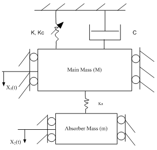 | Figure 1. Duffing Oscillator with Vibration Absorber |
The linear restoring spring of stiffness k and cubic nonlinear spring of stiffness kc are essentially one and is attached to the main mass. The arrow seen in this spring is used to indicate that cause is not proportional to effect; that the Hooke’s law does not hold for the nonlinear spring which is a reflection of all real-life problems. The two masses are not allowed to deflect side-ways since the mathematical models eliminate side thrust effect and thus confining the motion to the one of vertical oscillation. When excited, the duty of the absorber is to prevent excessive oscillation of the entire system in order to inhibit infinite vibration or resonance. In fact, the main mass is essentially stationary while the absorber oscillates. According to[11], the natural frequency of the undamped DVA is tuned to match the natural frequency of the main mass, thereby producing a force that is equal but opposite in direction to the excitation force, thus nullifying vibration at the resonant frequency. More extensive details about the principles of operation of a DVA can be found in the book by[12]. The mathematical model is a system of two second order nonlinear ordinary differential equations, (1) and (2). The equations are modified to include the mass ratio and are presented as equations (1a) and (2b). Though, no alteration was performed on (2b). Since the classical fourth order Runge-Kutta method cannot handle order higher than one, the equations had to be transformed into four sets of first order ordinary differential equations; and are simulated in this form. They are respectively equations (3), (4), (5) and (6). | (1) |
 | (2) |
The Modification Made: μ = ma/m | (1a) |
 | (2b) |
Equations (1a) & (2b) are transformed into the manner that is suitable for the Runge-Kutta model as follows: | (3) |
 | (4) |
 | (5) |
 | (6) |
where y1= x 1, y2= x'1, y3 = x 2, y4 = x'2, s = (c/mω), α1= (k/mω2), αc= (kc/mω2), α2= (ka/mω2), αa= (ka/mω2), F =Fo/mω2Further, in the study of a buckled beam[13], using the following parameter values: s = 0.168, α1= αc= 0.5, Fo = 0.21 and ω = 1, showed that the Duffing oscillator is chaotic. These parameters are used in this present study in order to ensure that the Duffing oscillator is chaotic before proceeding on finding the mass ratio for the purpose of controlling the system response.
2.2. Numerical Simulation
This numerical experiment involves studying the response of the system at the manipulation of the absorber parameters and the mass ratio of the system. In experimental analysis of this nature, it is necessary that we use certain established procedure to verify the outcome of the simulation. The simulation after hours of processing on a personal computer returns hundreds of data which we subjected to validation by examining the history of the system on phase space plots and Poincare maps. These data were used to determine the results that we have in the following paragraph.
3. Results and Discussion
3.1. Results
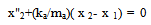
The results of this computer experiment are as shown in table 1. It comprises the so-called absorber parameters, the response of the system and the mass ratio at which these responses are observed. Figures two (2) through six were plotted by choosing from the pool of the values of mass ratio along with stated absorber parameters. Table 1. The concise results of tuning the mass ratio (μ) finely (at a step of 0.001) from 0 to 1.0 keeping constant all other specified absorber parameters1
 |
| |
|
 | Figure 2. The Poincare map of a Duffing Oscillator |
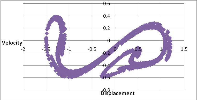
Historically, figure 2 is a Poincare map confirming that the data generated by the Runge-Kutta algorithm is chaotic and the attractor is strange, this is in agreement with the works of Dowell, and Narayanan, et al. This kind of attractor neglects the absorber mass effect. Other figure like 3 depicts the response of the system as period one motion. From table 1, we see that when the mass ratio (μ) is 0.012, the motion recorded is period one (1) at αa=1.1; and period two (2) motions when αa=1.7803, αa=1.9575 and αa=1.9576. These responses are examined for both the absorber and the main masses on phase space trajectories.  | Figure 3. The Phase Plot of Main Mass |
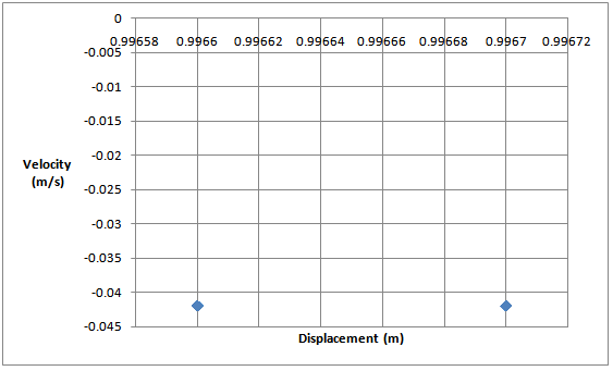
For the main mass, the phase space trajectory in figure 3 indicates periodic response when absorber parameter, αa = 1.1 and mass ratio μ = 0.0280. This is a period one (1) motion. Qualitatively, this oval object (figure 3) confirms that the motion is periodic since no intertwined loop is present – a limit cycle indeed. With a clearly defined locus of points, a view of this motion produces a “dot” on the Poincare map, as shown in figure 4. | Figure 4. The Corresponding Poincare section for period one (1) motion |
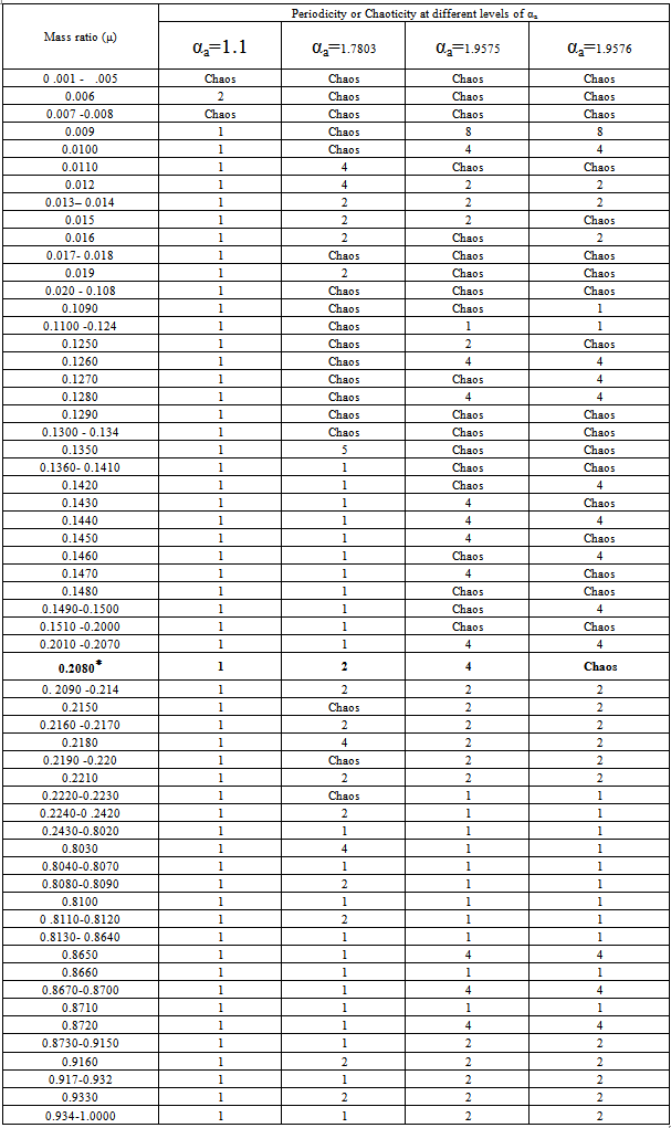
The Poincare map is the time history of the system. For a chaotic response, a complicated locus of point is observed on a phase plot having infinitely many points. 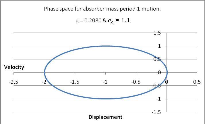 | Figure 5. The Phase Space of the Absorber |
And for αa = 1.1 at the same value of μ we obtained period one (1), shown in figure 5 for absorber motion. For the case in which αa = 1.7803 at the same value of μ we obtained period two (2) as shown in figures 6 and 7 respectively for the main mass and absorber motions. For a period two (2) motion, the Poincare map has two “dots” on its plane, see figure 8. 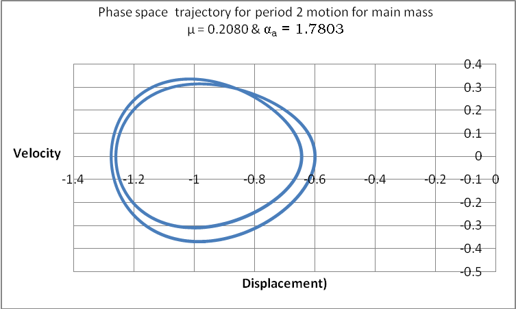 | Figure 6. The Period Two Phase Plot of Main Mass at µ=0.2080 and αa=1.7803 |
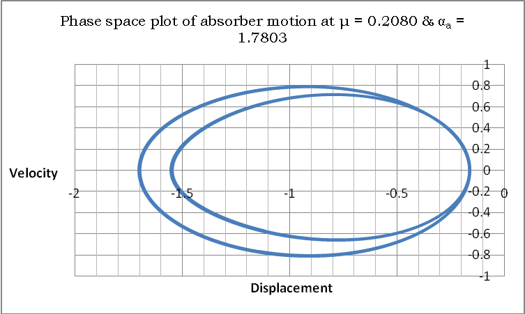 | Figure 7. The Period Two Phase Plot of Absorber at µ=0.2080 and αa=1.7803 |
 | Figure 8. The Corresponding Poincare map for period two (2) motion |
3.2. Discussion
The values of the mass ratio and the absorber parameters were used in this study with a focus on its temporal and spatial responses. If the stroboscopic time for any of such a point to revisit a particular point where it earlier visited is equal to or more than two-hundred and fifty six periods of excitation, then we interpret this response as chaotic. For this type of situation our algorithm returns ‘zero’ and the motion is considered chaotic.Where the system repeats at regular time interval, the motion is regarded as periodic and the mass ratio and the absorber parameter for which this response occurs are noted. Inserting these values into an algorithm designed to test for periodic or chaotic response, the algorithm returns a set of data which is plotted as phase-space trajectories and Poincare maps.From table 1, the first five result (i.e. from row one), the simulation returned zero as seen under the following respective values of αa: αa=1.1, αa=1.7803, αa=1.9575 and αa=1.9576 at μ = 0.001-0.005 suggesting that the system behaved chaotically. Furthermore, in row two of this table, the system responded like a linear system at αa=1.1 (column 2) and at a corresponding value of μ= 0.006 (mass ratio), this motion is recorded as period two (2) motion. And, at αa=1.7803, 1.9575 and 1.9576, at the same value of μ (i.e. 0.006), the system gave a typical response indicating chaos. For a μ = 0.016, we have one (1) period motion. At the same 0.016 mass ratio, it is a period two (2) motion. On a Poincare map, this should give two distinct points. This period doubling is generally in agreement with some of the earlier works; that, period doubling is a form of harbinger of chaos. As expected, the motion is chaotic after the period two (2) motions, and was followed by another period 2 motion. Again, this is clearly in agreement with the open literature, that periodic response is still possible after observing chaos.Further, during the interval where μ is between 0.201 – 0.207 at αa=1.1 and 1.7803 we recorded period one (1) motion (i.e. from columns 2 and 3); and, at αa=1.9575 and 1.9576 the simulation recorded period four (4) motions for both 1.9575 and 1.9576 values of αa , from columns 4 and 5.However, the row in bold face (from table 1) was highlighted to point to the difference(s) between the results of our numerical experiment and the one conducted by[8]. With specified absorber parameters obtained from[8], it is expected that we obtain the same result. This is true for columns 2, 3 and 4 but the last column of this highlighted portion of the table does not agree with the results of the work of[8]. This particular response points to our submission that absorber parameters alone (without µ) are not sufficient to render a Duffing oscillator periodic, yet are a necessary condition.
4. Conclusions
The chaotic responses exhibited by the two degrees of freedom (DOF) Duffing-Absorber system studied in this work were rendered periodic by making the ratio of the absorber mass to the main mass as the key parameter used to gain control over the system. This work also confirmed the age-long understating that when the time for a particular attractor to revisit a point in space is too far, we concluded that the system is chaotic and predictability becomes impossible for such a dynamical system. The absorber parameters specified were particularly invaluable in searching through the chunks of data returned by the simulation. It should be noted that absorber parameters alone are not sufficient to charaterise the system response. We picked the value(s) of the mass ratio that correspond with a particular absorber parameter while also noting the nature of the motion at play. In the study of nonlinear deterministic dynamical system, this kind of behaviour – transition from chaoticity to periodicity is one of many signs that show that cause is not directly proportional to effect as it is for linear systems. We do note that by specifying the mass ratio along with known absorber parameter values, this kind of nonlinear system would be made to behave like a linear system.
Notes
1. Chaotic response is defined in this work as the response when periodicity exceeds two hundred and fifty six.∗. Columns two, three and four agreed with the results obtained by [6], while the last column does not.
References
| [1] | Ian .G. Main, Vibration and Waves in Physics, Cambridge University Press, UK, 1995. |
| [2] | Garnett P. Williams, Chaos Theory Tamed, Joseph Henry Press, Washington DC, 1997 |
| [3] | Edward N. Lorenz, “Deterministic Nonperiodic Flow”, Journal of Atmospheric. Science, vol. 20, pp. 130-144, 1963 |
| [4] | Edward Ott, Chaos in Dynamical Systems, Cambridge University Press, UK, 1993. |
| [5] | Francis C. Moon, Chaotic Vibrations: An Introduction for Applied Scientist and Engineers, John Wiley and Sons, New York, 1987. |
| [6] | Paul S. Addison, Fractals and Chaos: An illustrated Course, IOP Publishing Limited, UK, 1997. |
| [7] | Robert C. Hilborn, Chaos and Nonlinear Dynamics: An Introduction for Scientist and Engineers, second ed., Oxford University Press, London, 2000. |
| [8] | S. Narayanan, K. Jayaraman, “Control of Chaotic Oscillations by Vibration Absorber”. ASME Design Technical Conference, 12th Biennial Conference on Mechanical Vibration and Noise. DE 18.5 pp. 391-394, 1989 |
| [9] | Earl H. Dowell, Computational Mechanics, Springer-Verlag, Volume 3. Number 3,199-216, 1988. doi: 10.1007 / BF00297446 |
| [10] | John M.T. Thompson, H. Bruce Stewart, Nonlinear Dynamics and Chaos, John Wiley and Sons, New York, 1987 |
| [11] | Online Availablehttp://www.scribd.com/doc/56748120/Dynamic-Vibration-Absorbers. (Accessed 18 February 2012) |
| [12] | Tomasz Krysinski, Fraoncois. Malburet, Mechanical Vibration – Active and Passive Control, ISTE Ltd, London. UK, 2007 |
| [13] | Earl .H. Dowell, Charles Pezeshki, “On the Understanding of Chaos in Duffing’s Equation Including a Comparison with Experiment”, ASME Journal Applied Mechanics, vol. 53 pp.5-9 1986 |
 Abstract
 Reference
 Full-Text PDF
 Full-text HTML