Chigbogu G. Ozoegwu 1, Sam N. Omenyi 1, Chinonso H. Achebe 1, Chigozie F. Uzoh 2
1Department of Mechanical Engineering, Nnamdi Azikiwe University, Awka, PMB 5025, Nigeria
2Department of Chemical Engineering, Nnamdi Azikiwe University, Awka, PMB 5025, Nigeria
Correspondence to: Chigbogu G. Ozoegwu , Department of Mechanical Engineering, Nnamdi Azikiwe University, Awka, PMB 5025, Nigeria.
| Email: |  |
Copyright © 2012 Scientific & Academic Publishing. All Rights Reserved.
Abstract
The model for regenerative vibration of linear orthogonal turning process is a second order time-invariant delay differential equation. Stability analysis resulted in lobes that combine to give transition curve that separates the parameter space of spindle speed and depth of cut into stable and unstable subspaces. It is found that there is a subspace of the stable subspace in which the turning process is delay-independent stable. The size of this subspace is found to be a function of modal parameters and increases with damping ratio of the tool. Non-linear analysis of turning by some investigators suggests that subcritical bifurcations always occur thus the need to design a portion of the subspace of delay-independent stability for global stability. The subspace of global stability is also theoretically and quantitatively demonstrated to increase faster than the driving increase in damping ratio.
Keywords:
Chatter, Delay-Independent Stable, Global Stability, Trajectories, Stability Transition Curve, Bifurcation
Cite this paper:
Chigbogu C. Ozoegwu , Sam N. Omenyi , Chinonso H. Achebe , Chigozie F. Uzoh , "Effect of Modal Parameters on Both Delay-Independent and Global Stability of Turning Process", Journal of Mechanical Engineering and Automation, Vol. 2 No. 6, 2012, pp. 159-168. doi: 10.5923/j.jmea.20120206.06.
1. Introduction
The general state space time-delay system with constant real matrix coefficients is | (1) |
where  and the history
  is on
is on . The coefficient matrices
  and
and  respectively captures the effects of discrete delay and distributed delay. Stability analysis has been carried out for the scalar version of this equation on the parameter space of coefficients of the current and distributed delay terms[1]. The interest in this work is on systems without distributed delay such that equation (1) becomes
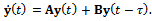 | (2) |
Equation (2) is said to be delay-independent stable if stability persists for all delay values belonging to  while it is said to be delay-dependent stable if stability is only retained for all delay values belonging to a subspace of
  [2]. Regenerative vibration of linear turning will be demonstrated in the next subsection to be governed by equation (2). It is known that one of the parameters affecting stability of turning operation is the spindle speed which is inversely proportional to discrete delay. This means that turning operation is delay-dependent stable.Trigonometric ideas are employed in a way unique to this work in detailed stability analysis of linear turning space regenerative vibration leading to demarcation of parameter of spindle speed and dept of cut into stable and unstable domains. It results that a portion of the stable domain of damped turning that lies below certain dept of cut is delay-independent stable being that asymptotic stability is retained within it at all spindle speeds; a notion first seen in this work.Subcritical nature of turning bifurcation has been experimentally and analytically established. This means that in practical setting, the space of delay-independent stability is not globally stable thus the need to establish a design procedure that enables the delineation of a portion of global stability in which regenerative chatter is deemed eliminated. The method of estimation of size and delineation of boundary of domain of global stability as outlined in this work is another major contribution of this paper.Among the contributions of this paper is the discovery that sizes of sub-space of delay-independent and global stability increase considerably with increase in damping ratio since it is theoretically established that fractional increase in these sizes are always greater than fractional increase in damping ratio. In other words, the pain involved in achieving greater damping will be more than compensated in gains in global stability.
2. Equation of Regenerative Vibration of Turning Tool
Figure 1 represents the turning of an external cylindrical surface. The workpiece at the rotational speed  in revolutions per minute of the spindle is clamped in a chuck while the tool is made to transverse it. The mechanical model in figure1 represents an orthogonal turning process. In orthogonal cutting process, the cutting edge of the tool is perpendicular to the feed motion[3] as can be observed from figure1. The modal parameters of the turning process are;
  mass of tool,
  is the equivalent viscous damping coefficient of the tool system and
  the stiffness of the tool system. Chatter is an unstable vibration in machining due regenerative effects that are originally triggered by internal and external perturbations. Regenerative effect as seen enlarged in figure1 is the effect of waviness created on a machined surface due to perturbed dynamic interaction between the tool and the workpiece. The present tool pass that is indicated as full curve has waviness that is not in phase with the last tool profile indicated as dashed curve. A variation in chip thickness causes cutting force variation that results in vibration which subsequently builds up to chatter if cutting parameter combination is unfavourable. In this model a single degree of freedom vibration is assumed in
  direction (feed direction). The tool is fed into the workpiece at a speed
 . Response
  of the tool system is measured relative to the unloaded equilibrium position of tool (or tool holder axis).The response of the tool
  satisfies the equation of motion that is as derived in what follows;
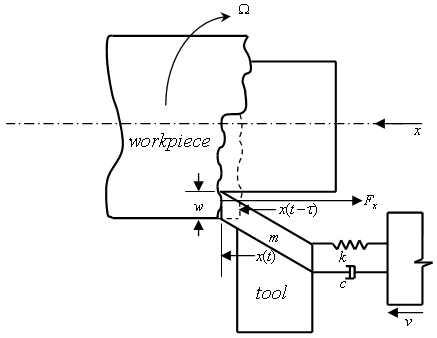 | Figure 1. Mechanical model of orthogonal turning |
The free body diagram for the tool system is figure2 and gives the equation of motion at an arbitrary time of cutting  as
as | Figure 2. Free-body diagram of tool dynamics |
 | (3) |
where  is the
  -component of cutting force.
  could have the empirical form found in the works of Tlusty[4];
  | (4) |
where  is the cutting coefficient (a property of the workpiece material),
  is the depth of cut,
  is the actual feed rate and
  is an exponent that has typical values
 . The latter exponent spells the three-quarter rule[4, 5]. Uniform feed rate
  is the prescribed movement of the tool’s cutting edge in meters per revolution of the workpiece thus the actual feed rate
  could be defined as difference of present and one period delayed position of tool if discrete delay equal to period of revolution is adopted. Thus from figure1 it could be seen that
 | (5) |
Putting equations (3), (4) and (5) together gives 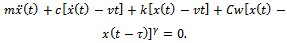 | (6) |
To make the derivation more compact the following notations are used;  and
and  . The notation also applies to any subsequent variable that involves delay. Applying the notation and re-arranging, equation (6) becomes
  | (7) |
The motion of the tool is a linear superposition of prescribed feed motion , static transverse deflection of the tool system
  and perturbation
  [4] then
 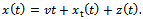 | (8) |
Straight-forwardly it goes that; 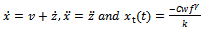 . For unperturbed motion of the tool
 giving rise to
 | (9) |
Equations (8) and (9) put in (7) gives | (10) |
Taylor’s series expansion of  about
about  results in equation (10) becoming
 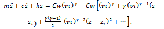 linearization of which yields
  | (11) |
The motion of the tool as described by equation (11) is seen to be a delay differential equation .The absolute value of the coefficient of  in equation (11) is called the specific cutting force variation and is given as
 . Equation (11) thus becomes
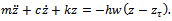 | (12) |
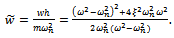
Equation (12) could be put in modal form 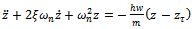 | (13) |
where the natural frequency and damping ratio of the tool system are given in terms of modal parameters  and
and  respectively as
  and
and . Equation (13) is seen to represent a delayed oscillator when re-written thus
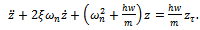 | (14) |
Equation (14) is the general equation governing linear regenerative vibration of the tool in turning process. The nature of the solution of equation (14) is a reflection of stability condition of an operation. If the perturbation motion or its derivatives rises with time, there is chatter (unstable operation) while bounded perturbation response with time implies non-chatter operation. With the substitutions  and
and  made, equation (14) could be put in state differential equation form
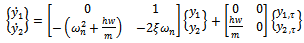 | (15) |
where  for
for and 2. The time domain equation (15) is the substance of stability characterization of turning process.
3. Chatter Stability Analysis of Turning
Equation (15) has the general form | (16) |
where 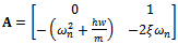 and
and 
 . This is an autonomous delay-differential equation with discrete delay. A trial solution of form
  [6, 7] put in equation (16) gives the equation
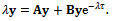 | (17) |
The characteristic equation of the tool system is seen from equation (16) to be  | (18) |
Upon simplification equation (18) becomes 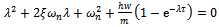 | (19) |
Expansion of the exponential term of equation (19) in Maclaurin’s series shows that the characteristic equation has infinitely many solutions or eigen-values also called characteristic roots, with each having the form  . Eigen-values of the system migrate on the complex plane as the cutting parameters are varied. All the roots must have negative real parts for the turning process to be stable thus operation is critical whenever there exist roots on the imaginary axis. Bifurcation in turning operation could occur when a pair of complex conjugate characteristic roots crosses from the left-half plane to right-half plane of the complex plane .This occurrence is called the Hopf bifurcation of a corresponding non-linear system. The trivial solution to equation (14) is
  where
where [7]. For any pair of complex conjugate roots
  there exists a solution
  being that equation (14) is linear. Since under bifurcation condition the critical characteristic roots are pure imaginary this solution becomes
 | (20) |
where  and
and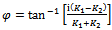 . Thus
  is seen to be the frequency of the arising chatter vibrations. This bifurcation of Hopf type has been proven experimentally by Shi and Tobias[8] and analytically by Stepan and Kalmar-Nagy[9] to have subcritical nature. This subcritical nature of turning bifurcation has implication in design engineering of machine tools as will be seen later.The stability boundary curves also called the D-curves or Stability lobes are drawn to separate the stable cutting domain (at which all
 ) from the unstable one ( at which some
 ). On the D-curves exist parameter combinations that produce a pair of roots of characteristic equation that are pure imaginary without any root existing in the right-hand plane. The D-curves could be tracked based on equation (19) by making the substitution
 . The two equations resulting are
 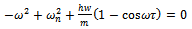 | (21) |
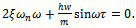 | (22) |
Equation (21) is violated when  suggesting that bifurcation of saddle node type is not expected in turning operation. Equations (21) and (22) could be solved to give expressions for critical cutting parameters
  and Ω as follows;From equation (22) results
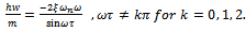 | (23) |
For positive depth of cut, equation (23) gives the condition . Equation (23) put into (21) gives
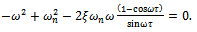 | (24) |
From the trigonometric relationship  equation (24) becomes
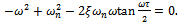 | (25) |
Since  then
then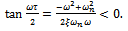 | (26) |
It is implied from (23) and (26) that  lies in any of the intervals where
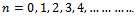 . From (26) sign inversion gives
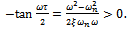 | (28) |
It could be seen from equation (28) that it holds the constraint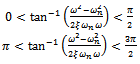 | (29) |
Such that from (28) results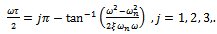 | (30) |
Therefore 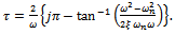 | (31) |
Though positive depth of cut is assumed in arriving at equation (31), the same result is achieved for negative depth of cut following a similar argument. If  is designated as
  in light of equation (31) then
 It then follows from result of (23) that
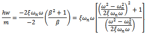 This becomes re-arranged to give the expression for critical depth of cut as
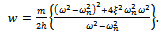 | (32) |
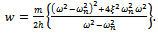
Stability charts are most often given in terms of cutting parameters like spindle speed  and depth of cut
  to give the range of technological parameters for non-chatter cutting. The pair of equations for stability analysis of turning thus becomes;
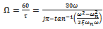 | (33) |
 | (34) |
Spindle speed and depth of cut are non-dimensionalized to give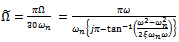 | (35) |
 | (36) |
Equations (35) and (36) are combined to generate a stability lobe for a particular . Stability lobes of various
  on the same parameter space are combined to give the stability transition or boundary curve for the linear turning process. It is seen from equation (36) that negative depth of cut results only when
  meaning that chatter frequencies are above the fundamental natural frequency of the tool since negative depth of cut has no practical meaning in turning. Also any value of
  results in the same critical depth of cut since
  does not appear in equation (36). For illustration, stability lobes for
  to 10 are generated to form the stability transition curve for a system with the parameters
  and
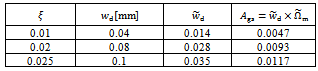
and . This is shown in figure3. Any point on the region below a combination of all the lobes is stable while those above are for chatter as is illustrated by six trajectories of figure4 generated at selected points of parameter space of figure3. Trajectories of figure4 are produced for a system with parameters;
  and
and ,
,  ,
,  ,
, , feed speed
 assuming a history
  and
and  in the interval
 . Each trajectory is determined by the corresponding cutting parameters of caption of figure4. It is obvious from figure3 that there is a sub-region of the stable subspace in which the operation is delay-independent stable since stability is retained no matter how high spindle speed gets. The nature of the solution of (15) is a reflection of stability condition of an operation. If the perturbation motion or its derivatives rises with time, there is chatter (unstable operation) while bounded perturbation response with time implies non-chatter operation. It is seen from figure4 a and b that a point
  on the phase plane at t=0 traces the trajectory towards the origin as indicated by arrow as time changes. This means that the points
  and
and  are stable in conformity with their location as marked star on the stability chart. The same point spirals away from initial position as time progresses for the operating points
 and
and  as seen in figure4 c and d. This implies instability which is expected since they are placed above the transition curve as marked with circle. The trajectories seem reluctant to get to origin in figure4e and d thus suggesting that the points almost lie on the stability transition curve as marked with diamond on the stability chart.
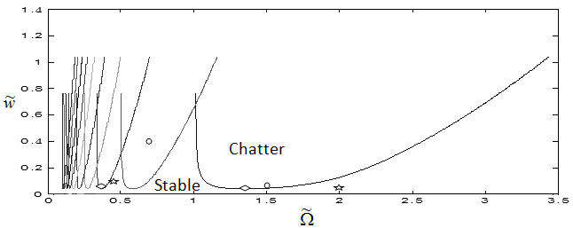 | Figure 3. Stability chart of linear turning with  |
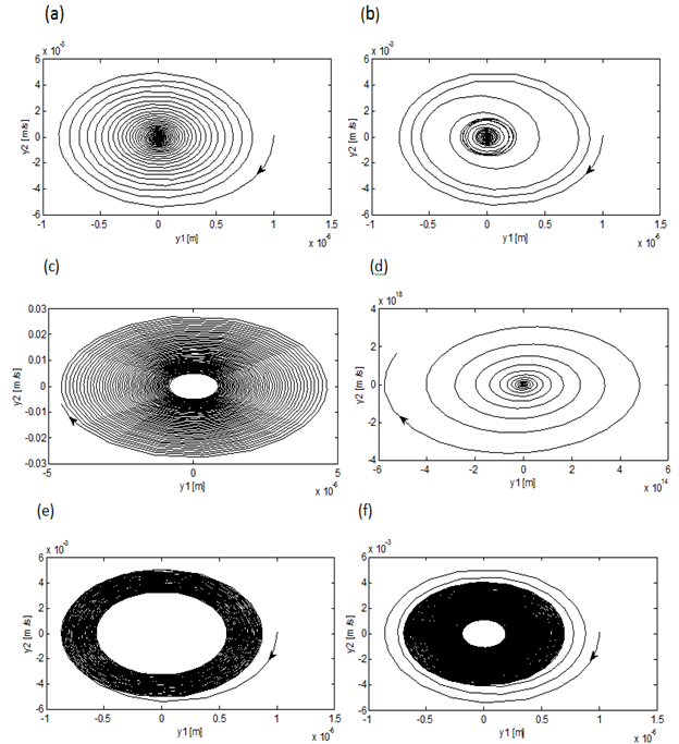 | Figure 4. linear turning trajectories with the determining parameters (a)  and and  (b) (b)  and and  (c) (c)  and and  (d) (d)  and and  (e) (e)  and and  and (f) and and (f) and |
4. Effect of Choice of Modal Parameters on Delay-independent Stability
From the equation | (37) |
results the polynomial equation | (38) |
which has the roots ,
, 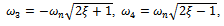
 and
and . Being that
  is positive and real and machine tools usually have low damping, generally,
  and
and  are neglected. The turning point frequencies thus become
  . These are respectively put into equations (35) and (36) to give the turning points of the transition curve on the
  parameter space as (
 ),
), and (
and ( ). Only the turning points (
 ) at
) at  are seen to make practical sense thus earn the emphasis here. The second derivative given by the equation
  | (39) |
results in a quantity  that is a function of modal parameters at the turning point boundary frequency of interest
 .
.  is a positive quantity for positive damping. The meaning is that the countable infinite number of turning points
 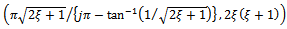 are minima on the
  parameter plane. It is seen that the minimum critical depth of cut is the same for all the stability lobes. It is also seen that increase in damping ratio results in increase in the minimum critical depth of cut. If the designations
  and
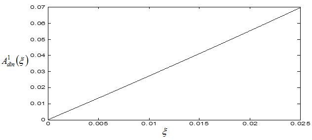
and  are made, a plot of local minimum points as damping ratio varies from 0 to 0.1 is shown for
  in figure5. This means that size of sub-region of delay-independent stability increases with damping ratio. Increase in damping ratio is effected by favourable variation of the tool modal parameters. It can be read from figure5 that increase in damping ratio will increase the sub-area of delay-independent stability by shifting the minimum critical points somewhat upwards and rightwards. If damping ratio is changed by the amount
 , the fractional increase in sub-area of delay-independent stability is
 | (40) |
Since damping ratio of machine tools are small, it could be writing that  causing equation (40) to be
 | (41) |
It is seen from equation (41) that fractional increase in the area of delay-independent stability is greater than that of damping ratio. In relative terms this means that there is considerable increase of delay-independent stable subspace of turning by increase of damping ratio.
5. Design Implications
It is already seen that linear turning is delay-independent stable in the sub-region below the line . In practical situation highest spindle speed of a turning machine normally lies either within low or high spindle speed domains. High spindle speed domain encompasses spindle speeds that are comparable with tool fundamental natural frequency. It lies within the first three lobes. For this reason the area of delay-independent stability enclosed by the lines
  and
and  together with the
  axes of size
 | (42) |
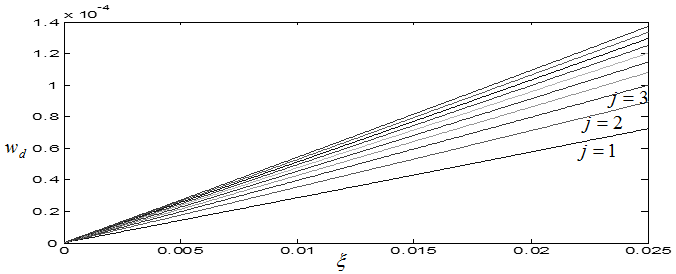
where  takes value depending on attainable spindle speed, is a function of positive slope of
  as is easily seen from figure6. This means that this area of delay-independent stability of turning increases as damping ratio increases.
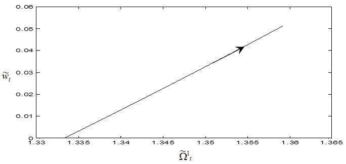 | Figure 5. Trajectory of minimum point of first lobe with  |
 | Figure 6. Variation of the bounded area  with damping ratio with damping ratio  |
 | Figure 7. Variation of design depth of cut  with damping ratio with damping ratio  for different lobes for different lobes |
Closed form bifurcation analysis has been conducted at the minimum points[9] in which it is found that though linear stability analysis suggests global stability at non-dimensionless depth of cut below  that bifurcation could still occur at a subcritical point due to non-linearity. This means that if minimum unstable depth of cut is specified for a turning tool and two modal parameters are known, the third modal parameter can be designed using the equation
  | (43) |
This is re-written to give the design equation | (44) |
where  is the design factor of safety that ensures global stability and
  is specified by the first minimum critical speed to be greater than the maximum spindle speed of the machine. Alternatively equation (44) could be used to establish the depth of cut below which global stability of a given turning is ensured.
  is chosen to preclude the possibility of non-linearities and perturbations triggering unstable vibrations at subcritical points. It has been measured experimentally that at the minimum points, chatter does not occur below 87% of critical depth of cut
 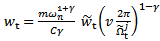 [8]. Based on this result it will amount to reliable design to specify that
 . It is seen that as
  increases, the maximum depth of cut that ensures delay independent stability increases. This means that the depth of cut designed by equation (44) increases as maximum spindle speed specification of the machine decrease. This result is seen clearly from figure7 in which
  is plotted against
  for different values of
 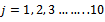 with
with  . Figure7 highlights the positive effect of damping ratio on global stability of turning. It also shows the importance of use of the biggest
  that specifies critical speed higher than the maximum spindle speed in equation (44) since slope rises with
 . It should be noted from the way the two terms “delay-independent stability” and “global stability” are used that the latter is a sub-domain of the former. To simultaneously quantify the notion that global stability is a sub-domain of the delay-independent stability and the finding that variation of modal parameters in a way that reflect as increase in damping ratio increases delay-independent stability and its subset of global stability, stability charts are generated for systems with parameters;
  and damping ratios
  and 0.025 respectively as seen in figures 8a, b, c, and d. It is seen from figure8.a that there is no delay-independent stable subspace for a turning tool with zero damping ratio. Delay-independent stable subspace is seen to exist when the damping ratio is non-zero as seen in figures 8b, c and d. Every stability chart of nonzero damping ratio on the right hand side is magnified portion of the adjacent chart to further reveal the subspace of delay-independent stability that lies below the line
 . The increase in this area with damping ratio is very noticeable as is expected from equation (41). The portion of this area for global stability depend on the maximum spindle speed and choice of the design factor
 For example if
 ,
,  ,
,  ,
,  ,
, ,
,  and maximum non-dimensionless spindle speed of the machines
 , use made of equation (44) results in what is presented in the table1 below. Column 4 of table1 is for area of global stability
 . This area for each chart of figure8 is enclosed within a black rectangle OABC and is seen to increase considerably with damping ratio according to equation (41). In conclusion, choice or variation of modal parameters of turning tool in a way that results in increase in damping ratio considerably improves both delay- independent stability and global stability. Through the method outlined in this work, the domain of global stability could be delineated for a real turning machine with known modal parameters.
 Table 1. Design depth of cut and area of global stability
 |
| |
|
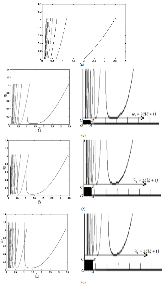 | Figure 8. Stability charts of linear turning showing domains of global stability for (a)  and and  (b) (b)  and and (c) (c)  and and , (d) , (d)  and and  |
6. Conclusions
Modelling and stability analysis of linear turning is carried out. It is found that variation of modal parameters in a way that results in increase in damping ratio improves stability. Ideas borrowed from results of non-linear analysis of turning are utilized in design to determine the domain and size of global stability which is a portion of the subspace of delay-independent stability in which subcritical chatter is not expected. The size of sub-space of global stability at any value of damping ratio depends on how conservative the design factor of safety  is where the basic condition satisfied is
 . It is established that sizes of sub-space of delay-independent and global stability increase considerably with increase in damping ratio since it is theoretically discovered in this work that their fractional increase is always greater than that of damping ratio causing it as equation (41) suggests. For example, row 2 and row 3 of table1 give that a percentage increase of 25.81 in area of global stability
  results from a percentage increase in damping ratio of 25 while equation (41) leads to computation of percentage increase in
  as
as . Any discrepancy between results of table1 which is developed from design equation (44) and those deriving from equation (41) stems from round off errors.
References
| [1] | C. Huang, S. Vandewalle, An Analysis of Delay-Dependent Stability for Ordinary and Partial Differential Equations with Fixed and Distributed Delays, SIAM Journal on Scientific Computing 25 ( 5) (2004) 1608–1632. |
| [2] | E.W. Kamen, P. P. Khargonekar, A. Tannenbaum, Stabilization of time-delay systems using finite dimensional compensators, IEEE Transactions on Automatic Control 30(1) (1985) 75–78. |
| [3] | V. John, Introduction to Engineering Materials, 3rd ed., Palgrave, Hampshire, 1992 p.3. |
| [4] | T. Insperger, Stability Analysis of Periodic Delay- Differential Equations Modelling Machine Tool Chatter: PhD dissertation, Budapest University of Technology and Economics (2002). |
| [5] | G. Stépán, R. Szalai, T. Insperger , Nonlinear Dynamics of High-Speed Milling Subjected to Regenerative Effect: to appear in the book Nonlinear Dynamics of Production Systems edited by Gunther Radons, Wiley-VCH, New York, 2003 pp. 1-2. |
| [6] | O. Diekmann, S. A. Van Gils, S. M. Verduyn Lunel, H. O.Walther, Delay Equations. Functional, Complex, and Nonlinear Analysis, Appl. Math. Sci. 110, Springer-Verlag, Berlin (1995). |
| [7] | G. Stepan, Delay-differential Equation Models for Machine Tool Chatter: in Nonlinear Dynamics of Material Processing and Manufacturing edited by F. C. Moon, John Wiley & Sons, New York, 1998 pp. 165-192. |
| [8] | H. M. Shi, S. A. Tobias, Theory of finite amplitude machine tool instability, International Journal of Machine Tool Design and Research 24(1984) 45-69. |
| [9] | G. Stepan, T. Kalmar-Nagy, Nonlinear Regenerative Machine Tool Vibrations, Proceedings of DETC'97 1997 ASME Design Engineering Technical Conferences, Sacramento, California, September 14-17, (1997). |
 Abstract
 Reference
 Full-Text PDF
 Full-Text HTML