Márcio Eduardo Silveira , Luize Scalco de Vasconcelos , André Luis Christoforo
Department of Mechanical Engineering, Federal University of São João del-Rei (UFSJ), São João del-Rei, 36307-352, Brazil
Correspondence to: Márcio Eduardo Silveira , Department of Mechanical Engineering, Federal University of São João del-Rei (UFSJ), São João del-Rei, 36307-352, Brazil.
| Email: |  |
Copyright © 2012 Scientific & Academic Publishing. All Rights Reserved.
Abstract
The use of numerical simulations in the design of automotive components has contributed to reducing the design time, decreasing the prototypes costs and increasing reliability of the final product. In addition, the search for solutions of low cost and satisfactory performance is essential for the success of the product in the world market. Twist-beam suspensions are an example of this competitive environment. This solution presents a very satisfactory performance when applied to light vehicles and has an excellent relationship between cost / benefit in the automotive market. It is estimated that more than 90% of light vehicles manufactured in emergent countries use this type of suspension at the rear. Despite its acceptance in the automotive market there are few studies related to the twist-beam suspension, perhaps because of its simplicity and low cost design and ease of manufacturing. Unlike other types of suspension, the twist-beam has a flexible torsion beam connecting the swing arms. The evaluation of the deformation of this flexible element becomes essential to understand their kinematic behavior. Thus, the use of software based only on the rigid body dynamics is not suitable to analyze this type of suspension. The main objective of this work was to evaluate through numerical simulation based on finite element method, the influence of the torsion beam on the kinematic behavior of a twist-beam suspension. It was evaluated the influence of both the position and orientation of the torsion beam on the suspension, under symmetric and asymmetric loadings.
Keywords:
Torsion Beam, Twist-Beam Suspension, Numerical Simulation
Cite this paper:
Márcio Eduardo Silveira , Luize Scalco de Vasconcelos , André Luis Christoforo , "Numerical Simulation of the Kinematic Behavior of a Twist Beam Suspension Using Finite Element Method", Journal of Mechanical Engineering and Automation, Vol. 2 No. 6, 2012, pp. 150-158. doi: 10.5923/j.jmea.20120206.05.
1. Introduction
The suspension of a vehicle consists of several components that are part of a system to generating comfort, stability and driving safety. Basically, it has the following functions [1]:• To isolate the chassis of the irregularities of the runway, through the action of its elastic and damping elements;• To allow the wheels, since the angles at handling are determined, remain as closely as possible;• To support reactions imposed by the tires, transmit acceleration and support the braking as well as lateral forces and moments resulting from these efforts;• To react to the tendency of body roll;• To keep the tires in contact with the floor, even under small load variations.The dynamic properties of a suspension are first seen in the kinematic behavior and its response to the forces and moments that it should pass of tires for the chassis. Other characteristics considered in the project are cost, weight, packing factor (space in the vehicle), manufacturing, ease of assembly and others. A kinematic effect is the change in camber angle which according to DIN70000 standard[2], is the angle between the central plane of the wheel and vertical to the plane of the track. By definition, the angle is positive if the wheel is inclined out on the top, and the contrary is defined as negative. The camber is essential in vehicle stability when cornering. In independent suspensions there is a natural behavior of the wheels follow the rotation of the body, generating, for example, positive camber values for external wheels. However, negative camber in the external wheels in a curve becomes critical to increase the adhesion.The convergence angle (or toe angle) in accordance with DIN70000 standard[2], is the angle between the central plane of the vehicle in the longitudinal direction and the line of intersection of the central plane of the wheels with the floor plane. Is positive when the distance between the anterior part of the wheels is smaller than the posterior, and negative the opposite. The convergence directly affects three areas of vehicle handling: tire wear, straight-line stability and security features in the entries of curves.Rolling is the effect of body roll on cornering due to the centrifugal force and the height of the centroid that impose a load on the external wheels tending to compress the outer springs and to stretch the internals. Moreover, the rolling can transmit information to the driver about the limits of adhesion of the vehicle, in addition to the condition of the curve. The limitation of the rolling, usually conflicts with the comfort of the vehicle, because each rolling feature requires specific choices of springs and dampers. However the factor of choice of the type of geometry and appropriate suspension system can to harmonize the effect.According Reimpell[3], suspensions of the vehicle can be divided into rigid axles (with a rigid connection between the wheels), independent suspensions, in which the wheels are fixed to the chassis independently and the semi-independent that combining characteristics of the rigid axle and independent suspensions.In rigid axles (or dependent suspension), one side of the suspension depends on the other hand, due the two sides are connected on the same axis. Thus, when the wheel passes over a bump, the other side is inevitably interfered. So, the body will incline in a certain angle, which may affect the stability in some situations. However, the rigid axle has the advantage of distributing the weight of the vehicle uniformly being used in many commercial vehiclesThe independent suspension system operates in a manner to promote a higher performance with respect to stability. The wheels are not connected to one another, so, if one side of the suspension lift, the other remains in its normal state and the vehicle body remains straight, and its trajectory unchanged. Currently, passenger cars and light trucks use independent suspension in front, because the advantages, such as more space for the engine and better resistance to the shimmy, are factors that make this type of suspension as an excellent choice for use in the car front. Another advantage that may be mentioned is the easy control of kinematic points by selecting the geometry of the control arms[2]. 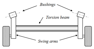 | Figure 1. Example of a typical twist-beam suspension |
The suspension semi-independent best known is the twist-beam, which combining characteristics of the dependent and independent suspensions. Basically consists of two longitudinal swing arms (or trailing arms) attached to the chassis and the wheels. Interconnecting the arms there is a torsion beam (usually stamped), forming a typical H-shaped for this type of solution, Fig. 1. When a wheel undergoes an impact, the beam will twist and some of the shock is absorbed, reducing its transmission to the opposite wheel. In principle, the possibility of twisting becomes this axis a stabilizer, dispensing the stabilizer bar in some cases. This type of suspension is used only in the rear of vehicle and usually not driving axles.Considering the competitiveness of the automotive market current, the search for cost-effective solutions that meet all quality requirements, it has become essential in the process of product development. The principles of large-scale production have become a limiting complexity of the components, mainly due to difficulties in the manufacturing process. This background requires agility in the design of vehicles forcing a high degree of specialization on the engineering, to produce quick results, simple, low cost and meeting the expectations of customers of a specific market.Twist-beam suspensions are an example of this competitive environment. This type of solution provides perhaps the simplest design of suspensions, in view of the manufacturing process, of all these solutions on the market today, representing very satisfactory results when applied in light vehicles[4]. Due to the facilities and the low cost series production of stamped parts, it established a trend in emerging markets. This solution presents itself with an excellent relationship between cost / benefit for the Brazilian market, generating the need of accurate knowledge in the design variables for this conception. It is estimated that more than 95% of light vehicles in Brazil produced using this type of suspension at the rear.Despite the large use in the Brazilian automotive market, there are few studies related to the twist-beam suspension. The torsion beam is perhaps the most important component of this type of suspension. Factors such as moment of inertia, polar moment of inertia and neutral axis position may significantly change the behavior of the suspension. The profile of the beam torsion is essential to control parameters such as radius of turn, vertical reaction wheels, convergence and camber[4]. There are several solutions to the shape of the cross section of the torsion beam, the most common profiles in U, V and C reversed. These solutions are commonly utilized mainly due to its ease of fabrication and assembly, and the torsional stiffness basically defined by the thickness of the sheet of the beam. There is little literature available on the project and research in suspensions of this type, perhaps because of its simplicity and low cost of design and manufacturing (compared to other types of suspension).The use of numerical simulation based on Finite Element Method in the analysis of automotive components is fundamental to the rapid development of the project, reducing costs and reducing time for the product reaches the market[5],[6],[7]. Currently there are several simulation software market, with robust formulations to simulate events with high nonlinearity, quasi-static or dynamic. The evolution of hardware allows now be possible to perform simulations of events with high complexity in multi- processor PCs. The use of numerical simulation via finite elements and dynamics of rigid bodies has been widely used during the stage of virtual designs of suspension system, achieving good correlations with experimental results[8].There are some related works that use or compare different computational models of torsion beam suspension systems. Sugiura et al.[9] presented a software for automatically generate a reduced stiffness matrix of a torsion beam which is an application of First Order Analysis[10],[11],[12]. The design tool can be run in a personal computer and do not require that the design engineers have special skills in modeling or analysis. But the software is somehow limited because it does not enable using variable profiles along the beam and also there are three possible locations predetermined of coil spring. Sinokrot el at[13] presented two different multibody system modeling techniques for the simulation of flexible twist beam axles. One uses the method of component mode synthesis together with a sub-structuring technique for modeling the flexible beam that is done by dividing the beam into a set of sub-structures each of which is flexible. In the other approach, an external nonlinear FEA solver is used in modeling the flexible beam coupled with the general multibody system solver that is used in modeling the rest of the car suspension system. However, it was found that the substructuring approach results in higher axial torques at the connection points where the beam connects to the trailing arms and the Von Misses stress results showed that undesired stress concentrations appear at the junction between adjacent sub-structures. The advantage of using the sub-structuring approach was found to be in the simulation time where the time required was significantly less than that needed for co-simulation where a small communication interval was needed for this application. Lyu et al[14] presented the lumped compliance linkage model method in which the torsion beam is represented as a linkage of lumped mass joined by nonlinear springs, bending and torsion, whose stiffness are identified via off-line computational experiments using nonlinear finite element simulations without using flexible bodies. It enables both interactive design examination and batch-mode optimization of the torsion beam suspension systems.The main objective of this work was to evaluate through numerical simulation based on finite element method, the influence of the torsion beam on the kinematic behavior of a twist-beam suspension. Thus, it was proposed a suspension containing flat arms to make feasible to change the profile of the beam. It were evaluated the influence of factors such as moment of inertia and polar moment of inertia of the torsion beam on the convergence and camber of the suspension for different type of load. Stress analysis will not be evaluated in this study.
2. Methodology
This work is part of a larger project where the final proposal will conduct a comparative analysis of the influence of the geometry of the torsion beam on the kinematic parameters of the suspension. Initially, it will be evaluate the influence of the position and orientation of a torsion beam with profile "C" in camber and toe angles.With this aim, it has been proposed a "fictitious" suspension in order to make feasible the change of position and orientation of the torsion beam along the swing arms. Thus, the suspension developed for this work has plans swing arms in order to facilitate the reorientation and repositioning of the beam along the arms, Fig 2.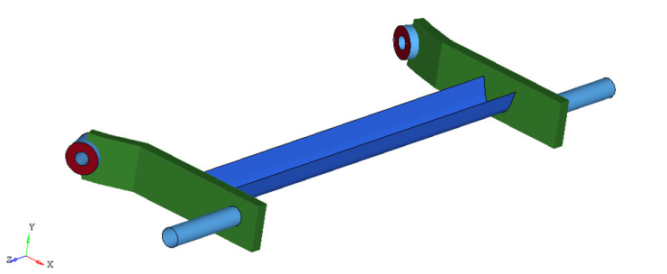 | Figure 2. Twist-beam suspension proposal in this work |
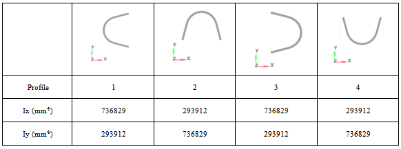
At first, it was proposed a "C" profile for the torsion beam. Turning this profile at 90º, it was obtained four different configurations for the torsion beam, as shown the Fig. 3. It can be observed that, while the profile is the same, the rotation of the torsion beam change in the moments of inertia on x and y axis of the suspension, which may result in a different kinematic behavior.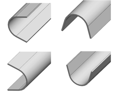 | Figure 3. Profile of the torsion beam |
In addition the analysis of the influence of the profile orientation, it was also evaluated the position of the torsion beam along the swing arms, as shown the Fig. 4.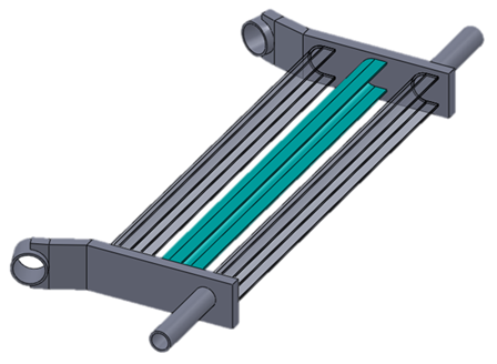 | Figure 4. Possible positions of the torsion beam along the swing arm |
In order to simplify the design and analysis, the following considerations were made in the numerical simulation:• All analyses were linear static (dynamic and viscous effects were ignored). Both the torsion beam and the other metal components were modeled with plate elements with six degrees of freedom and linear interpolation.• The bushings and springs were considered as being linear elastic. The bushing was modeled with solid elements and springs with 1D elements.• The influence of the swing arms and the positions of the springs and dampers in the final results will not be evaluated in this study.• In order to obtain a suspension simplified were considered only fundamental components, whose main material and geometric properties are given in Table 1. | Table 1. Thickness and Young's Modulus of the main components of the suspension |
| | | Thickness (mm) | Young'sModulus (MPa) | | Swing arms | 4 | 210000 | | Torsion beam | 4 | 210000 | | Wheelsupportingaxle | 5 | 210000 | | Bearing | 5 | 210000 | | Bushing(rubber) | - | 5 |
|
|
Regarding to the boundary conditions, both asymmetrical and symmetrical loadings were considered. The forces were applied at the end of the wheel supporting axle in the vertical direction (y direction) and motion constraints were set at the centre of bushings and at the spring support, restricting translation in all directions (rotation was allowed), as shown in the Fig. 5. The initial position of the suspension was considered parallel to the ground and the initial loading due the weight of the vehicle was not considered. Also, the suspension travel was not restricted, the camber and toe angles were measured for four magnitudes of forces (100N, 200N, 300N and 400N) and graphics were plotted in function of the respective suspension stroke obtained for each force.It must be emphasized that, given the simplifications imposed in the model, the achieved results don't have the pretension to approach to a commercial suspension, since the objective is to conduct a qualitative analysis of the influence of the torsion beam. Thus, the suspension developed in this work has goals essentially academic.All the simulations were performed in the commercial software Radioss Bulk Data and the post processing in the Hyperview.[15]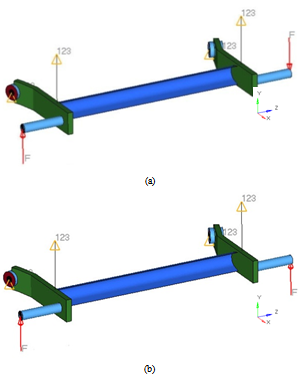 | Figure 5. (a) Asymmetrical and (b) symmetrical loadings |
3. Results
For better interpretation of results, it was conducted a survey of the moment of inertia of the profiles relative to the centroid, whereas all the profiles are the same, rotated 90 degrees between them. These data are shown in Table 2.The analysis of the results was divided into two parts, the first assesses the influence of orientation of the profiles and the second considers the position of the torsion beam along the swing arm.Table 2. Moment of inertia of the profiles at the centroid
 |
| |
|
3.1. Orientation of the Twist Beam
3.1.1. Symmetrical Stroke
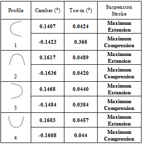
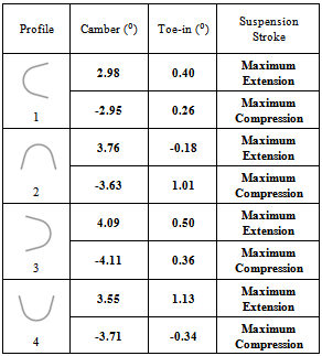
Table 3. Camber and toe-in results on the bottom and on the top of the suspension travel
 |
| |
|
The Table 3 shows the camber angle and the toe-in angle on the maximum compression and on the maximum extension of the suspension. In this case, the torsion beam is subjected to flexure efforts that cause variation of the camber angle, as it is shown in the Fig. 6.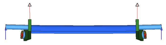 | Figure 6. Illustration of suspension in bending distortion |
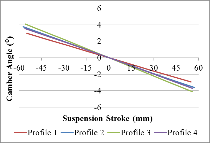
Thus, it can be concluded that the higher the inertia about the X axis, the smaller the variation of camber. It is evidenced in the Fig. 7, that the change in the camber angle is less for profiles with high IX (1 and 3).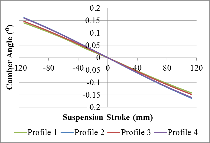 | Figure 7. Comparison of camber results for symmetrical |
With the suspension travel, occurs a rotation of the suspension arm, as shown in Fig. 8, which causes a percentage of the camber angle, created due the deformation of the set, to transform into toe-in angle.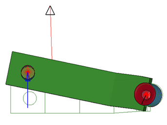 | Figure 8. Illustration of the swing arms rotation on the maximum extension of the suspension |
Thus, in compression, negatives camber angles are converted into positive toe-in angles and vice versa. And, in expansion, positive camber angles are converted into positive toe-in angles and vice versa. The occurrence of this fact can be seen comparing the behavior of the diagrams of the Fig. 7 (camber change) and the Fig. 9 (toe-in variation). It can also be seen that the profiles of less toe-in variation (1 and 2) are the profiles of less camber variation.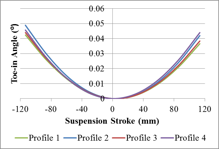 | Figure 9. Comparison of the toe-in results for symmetrical stroke |
In the case of symmetrical loading, large changes of camber and toe-in are not desirable because it may result in excessive tire wear. Thus, the profile C is found to be more advantageous.
3.1.2. Asymmetrical Stroke
The Table 4 shows the camber angle and the toe-in angle on the maximum compression and on the maximum extension, created on asymmetrical loading for all the orientations presented.First of all, it was evaluated the influence of the profiles in the vehicle cornering behavior by analysis of Figs. 10, 11, 12 and 13, of camber and toe-in variations .It is possible to observe that all profiles have a tendency to negative camber in compression. This behavior is fundamental to maneuver of the cornering, since it increases the contact area between the tire and the ground which generates more grip, avoiding the oversteer behavior of the vehicle.Table 4. Camber and toe-in results on the bottom and on the top of the suspension travel
 |
| |
|
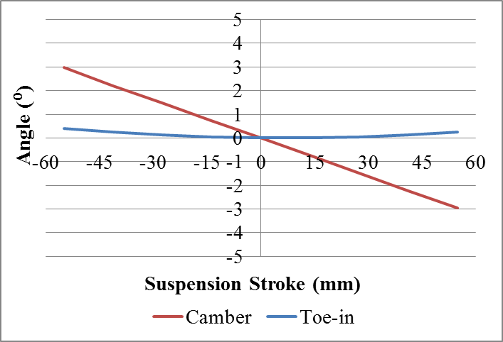 | Figure 10. Profile 1: Toe-in variation and camber variation during vertical suspension travel |
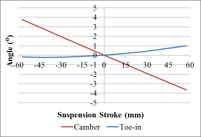 | Figure 11. Profile 2: Toe-in variation and camber variation during vertical suspension travel |
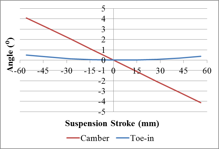 | Figure 12. Profile 3: Toe-in variation and camber variation during vertical suspension travel |
The profiles 1, 3 and 4 show a tendency to positive values of toe-in during the compression which is a desirable effect on bends, because contributes to the neutral behavior of the vehicle[3]. However, the profile 4 showed a trend of toe-out in compression, which might lead the vehicle to oversteer.The Fig. 14 shows the comparison between the results of camber from all profiles, where it is possible to examine how the rotation of the profile influences the behavior of the suspension. 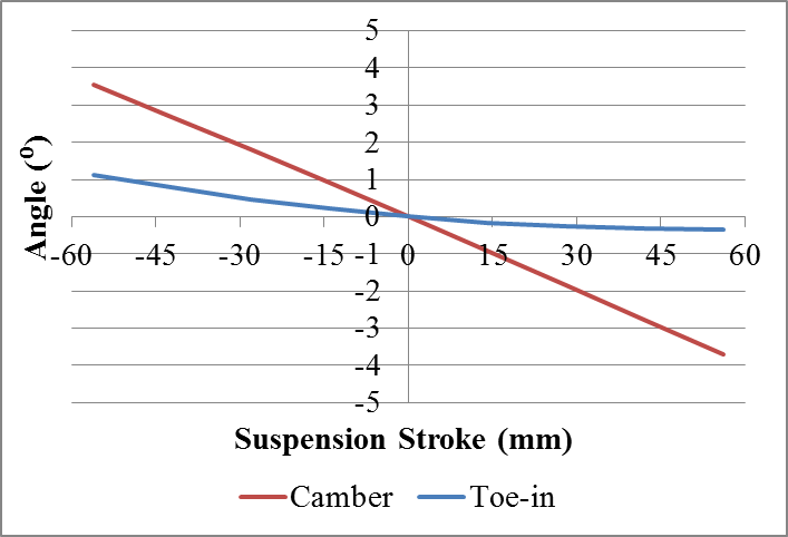 | Figure 13. Profile 4: Toe-in variation and camber variation during vertical suspension travel |
 | Figure 14. Comparison of camber results for asymmetrical stroke |
The asymmetrical displacement of the suspension causes a twisting of the torsion beam that generates an important phenomenon in the tabs of these types of profiles ("U" and "C"). As illustrated in Fig. 15, this cause opposite movements of the end flaps in Z direction. This movement is essential in the generation of camber angles and toe-in angles.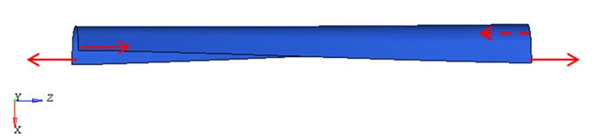 | Figure 15. Top view of the deformation of the profile 1 and the trend of movement of its ends |
As mentioned, there is a trend of negative camber angles in compression and positive camber in extension. Profiles "C" (1 and 3) when twisted, can help manage these angles. The movement of the tabs of torsion beam, shown in Fig. 15, on compression, generates positive camber angle if the "C" profile is directed behind the vehicle (profile 1) and generates negative camber angle if the profile "C" is directed forward ( profile 3). The opposite happens on extension. This effect can be observed in Fig. 14, where the profile 1 presents the smallest camber angle variation, ie the design of profile "C" directed back tends to minimize the angle of camber. This design also enables the use of profiles with lower values of moment of inertia about the x axis. However the profile 3 ("C" directed forward) has a reverse tendency, that is, the twisting movement of torsion beam causes negative camber angle on compression and positive camber angle on the extension, which added to the natural tendency of movement of the body tends to maximize the camber angles.Figure 16 shows a comparison of the toe-in variation of all profiles.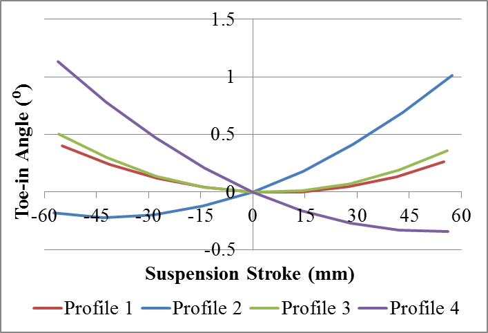 | Figure 16. Comparison of the toe-in results |
The attitude of toe-in, positive or negative, from the profiles 2 and 4, is strongly influenced by the torsion behavior of the "U" profiles. That is, the displacement of the tabs in the direction Z of U-shaped profiles guides the swing arm to toe-in or toe-out. It can be seen from Fig. 16 that the profile 2 ("U" facing down) tend to toe-in in compression and to toe-out in rebound. The profile 4 ("U") has the opposite behavior.
3.2. Position of the Torsion Beam
For the analysis of the influence of the position of the torsion beam along the swing arms, it was considered the 3 different positions showed in Fig. 17.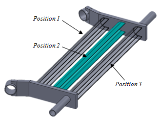 | Figure 17. Positions of the torsion beam |
These positions were evaluated in both symmetrical and asymmetrical motion, and the conclusions were similar for both.
3.2.1. Symmetrical Stroke
The Fig. 18 and Fig. 19 show, respectively, a comparison of the camber changes and the toe-in variation for each position.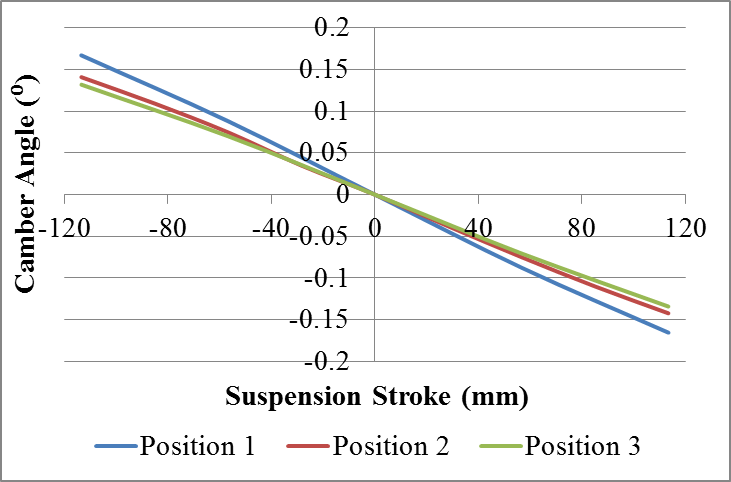 | Figure 18. Comparison of camber results for different positions of the torsion beam with symmetrical loading |
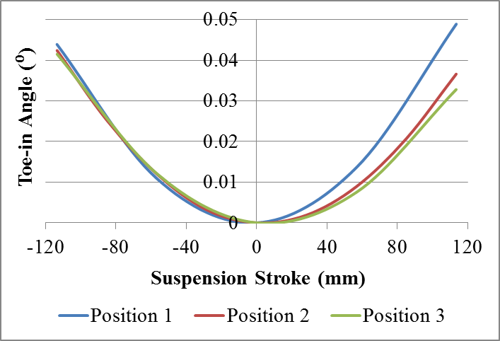 | Figure 19. Comparison of toe-in results for different positions of the torsion beam with symmetrical loading |
Looking at the graphs it is possible to notice a slight difference in the results due to the transfer of the beam. With the torsion beam approximation of the bushings there is a reduction of the deformation of the beam which in turn result in less variation of both the camber angle as the toe-in angle.
3.2.2. Asymmetrical Stroke
The Fig. 20 shows a comparison of the camber changes for each position.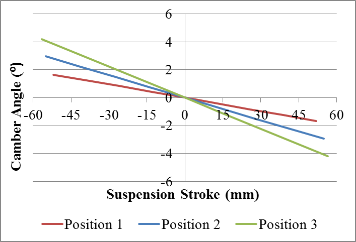 | Figure 20. Comparison of camber results for different positions of the torsion beam with asymmetrical loading |
It can be seen that for asymmetrical stroke there is also an amplification of camber angle as the torsion beam move towards the rear of the vehicle. This occurs because the greater the distance from the pivot point (bush), the greater is the displacement and, therefore, there is a bigger torsion of torsion beam generating higher angles (Fig. 21).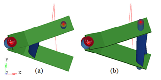 | Figure 21. The difference of displacement of the torsion beam in the positions 1 and 3: (a) side view of deformation increased three times of the suspension with the beam in the position 1; (b) side view of deformation increased three times of the suspension with the beam in the position |
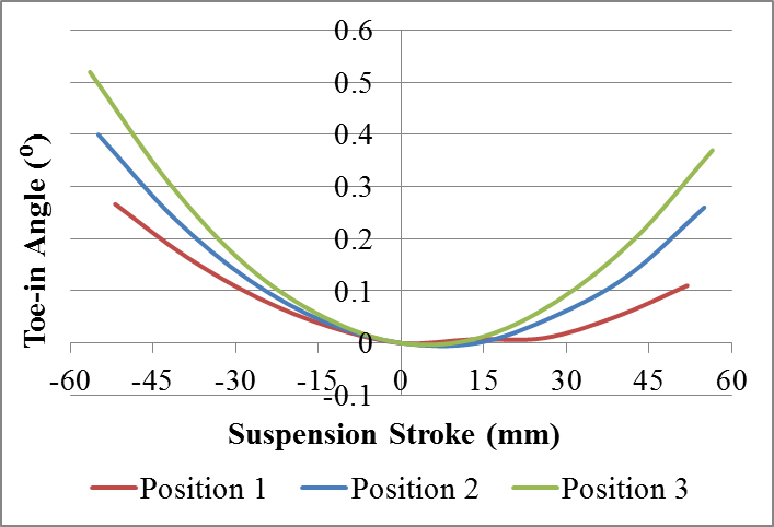 | Figure 22. Comparison of toe-in results for different positions of the torsion beam with asymmetrical loading |
The same analysis of camber applies for toe-in, ie, the greater is the distance from the bush, the greater is the magnitude of the movement of toe-in (Fig. 22). It is also important to note that stresses will also be larger in the position 3 due to its larger displacement.
4. Conclusions
Unlike other suspension types, the twist beam suspension has a deformable member (torsion beam) connecting the two lateral arms (swing arms). This makes it impossible to use a multi-body system simulation software to predict the kinematic and dynamic behavior of the suspension. Thus, the objective of this study was to use the finite element method to evaluate the influence of torsion beam on the kinematic behaviour of the twist-beam suspension. The suspension was simulated on symmetrical and asymmetrical travel, changing the position of the torsion beam along the swing arm and its orientation. It was proposed a suspension with flat swing arms to minimize the effect of difference in geometry at the junction of the torsion beam with arms. Then, it was measured the resulting values of toe-in and camber for each case and plotted graphics to analysis. Those are important characteristics to be evaluated in the design of the suspension because they influence the behavior of the vehicle when cornering. By analysing the results, it was possible to see that the orientation of the profile can maximize, minimize and even reverse these angles. The Profile 1 showed a better performance than the others both in symmetric and asymmetric displacement. When examining symmetrical loading, the main fact to be considered is the moment of inertia about the x axis because in this case, the torsion beam is subjected to flexure efforts that cause variation of the camber angle. Hence, the profiles 1 and 3, which have the same Ix, presented smaller variation of camber than the profile 2 and 4 with lower IX. For asymmetrical loading, it was found that the tabs of an open profile have great influence on the behavior of the suspension. When the beam twists the tabs move in the z direction affecting the camber or toe angles, depending on the orientation of the profile. For profiles of type “U” the tabs affect mainly the toe-in movement, whereas for profiles of type “C” the main influence is on the camber angle. Because of this effect, the Profile 1 has the tendency to minimize the magnitude of the camber angles, enabling the use of profiles with lower IX. Regarding the factor of the beam position, it was revealed that the closer the position to the pivot point of the swing arm, the smaller is the variation of both camber and toe-in angles. However, these preliminary results are part of a larger project, which will be evaluate various parameters regarding the influence of the torsion beam: different profile types (both open and closed profiles/hydroformed, asymmetric profile, etc); torsion beams with variable cross section along the length; torsion beams with length nonlinear. The goal is to have a detailed view of the influence of the torsion beam behavior in a twist-beam suspension, in order to better assist in the development of vehicles that use this type of suspension, in increased use on the world market.
References
| [1] | Gillespie, T. D. Fundamentals of Vehicle Dynamics. Society of Automotive Engineers SAE, Warrendalle, 1992. |
| [2] | DIN 70000, Road vehicles; vehicle dynamics and road holding ability, 1994. |
| [3] | Reimpell, J.Stoll, H. The Automotive Chassis: Engineering Principles. Great Britain, 1996. |
| [4] | Leal, V. Estudo Cinemático de Suspensões Veiculares do Tipo Eixo de Torção. Dissertação de Mestrado. PUC-Minas, Belo Horizonte, 2007. |
| [5] | Silveira, M.E., Passos, F. M., Samesima, F.T., Dares, J.A., Diniz, F. G., Lemos, M.S. Implementation of a correlation technique for fuel tank sled crash test. SAE Technical Paper 2009-36-0209, 2009. |
| [6] | Vieira, A. L., Pockszevnicki, B. C., Vera, E. Q. N., Mesquita, D. R., Silveira, M. E. Hardening and final thickness data used in the quasistatic nonlinear analysis of stamping parts. MecánicaComputacional, Vol 29, pp. 1913-1924, 2010. |
| [7] | Vieira, A. L., Silveira, M. E., Pockszevnick, B. C. Vera, E. Q. N. The effect of stamping data on the palm printing analysis of an automotive fender. SAE Technical Paper 2011-36-0274, 2011. |
| [8] | Holdmann, P., Köhn, P., Möller, B., Suspension kinematics and compliance - measuring and simulation. Society of Automotive Engineers, 1998. |
| [9] | Sugiura, H., Mizutani Y., Nihigaki H., First Order Analysis for Automotive Suspension Design. Technical Journal - R&D Review of Toyota CRDL. Vol. 37. No. 1, 2002. |
| [10] | Kojima, Y., First Order Analysis as CAE for Design Engineers. Technical Journal - R&D Review of Toyota CRDL. Vol. 37. No. 1, 2002. |
| [11] | Amago, T., Sizing Optimization Using Response Surface Method in FOA. Technical Journal - R&D Review of Toyota CRDL. Vol. 37. No. 1, 2002. |
| [12] | Nishiwaki, S., Structural Optimization Based on Discrete Elements. Technical Journal - R&D Review of Toyota CRDL. Vol. 37. No. 1, 2002. |
| [13] | Sinokrot, T. Z., Prescott W. C., Nembrini, M., Toso, A., Multibody System Modeling of Flexible Twist Beam in Car Suspension System. Proceedings of ASME 2011 International Engineering Congress & Exposition, Denver, 2011. |
| [14] | Lyu, N., Park, J., Urabe, H., Tokunaga, H., Saitou, K., Design of Automotive Torsion Beam Suspension Using Lumped-Compliance Linkage Model. Proceedings of IMECE: ASME 2006 International Mechanical Congress and Exposition, Chigago, 2006. |
| [15] | Online Available: http://www.altair.com/. |
 Abstract
 Reference
 Full-Text PDF
 Full-Text HTML