L. Savin 1, E. Slivinsky 2, D. N. Klimov 1, S. J. Radin 2
1State University , Educational, Science, Production Complex, Orel, Russia
2Yelets State University name I.A. Bunin, Yelets, Russia
Correspondence to: S. J. Radin , Yelets State University name I.A. Bunin, Yelets, Russia.
| Email: |  |
Copyright © 2012 Scientific & Academic Publishing. All Rights Reserved.
Abstract
In this article questions on creation and calculation of a perspective design of adaptive torsion suspension for the locomotives, including hydromechanical dampers of fluctuations of adaptive type. The design procedure of the main kinematic and geometrical characteristics on a locomotive example 2ТЭ10Л, supplied with the specified technical solutions, and studying of fluctuations and power loading of its running gears is offered. Thus, the dynamic settlement scheme on the basis of Foygt-Kelvin's elastic and viscous model is developed. The bench pilot studies, allowed to specify parameters and characteristics of the above-stated designs are carried out. Expected economic effect of possible introduction of development will make 850 thousand rubles a year on one locomotive. Materials of this article were discussed at various conferences of leading higher education institutions of the Russian Federation. Results of researches are recommended to design, research and machine-building structures for their possible use in practice.
Keywords:
Adaptive, Hydromechanical, Damper, Torsion, Suspension, Torsion Rate, Locomotive
Cite this paper:
L. Savin , E. Slivinsky , D. N. Klimov , S. J. Radin , "Complex Research of Perspective Suspension for Locomotives", Journal of Mechanical Engineering and Automation, Vol. 2 No. 6, 2012, pp. 140-149. doi: 10.5923/j.jmea.20120206.04.
1. Introduction
Modern rolling stock, including locomotives, passenger and freight cars is the most important constituent part of the technical facilities of railway transport characteristics, properties and parameters of which are determined by the growth of traffic, increase traffic speed, ensuring operational reliability, increase the comfort of passengers and the smooth progress of railway carriages, cargo safety, etc. Such requirements are directly connected with the improvement of their spring suspension, aimed at reduction of dynamic loads transmitted from the track of the body and crews and thus increasing the smoothness of the rail vehicles. The existing design elements spring suspension of rolling stock have a number of drawbacks, such as a high metal content, complexity of design, low reliability and, most importantly, the inability to change in the automatic mode of their damping characteristics.
2. Objectives
In view of the foregoing at the chair "Applied mechanics and engineering graphics" Yelets State University name I.A. Bunin for a number of years carried out the research works aimed at creation of perspective of a torsion spring suspension for railway vehicles, which includes adaptive torsion springs and adaptive hydromechanical dampers.The subjects of such research is based on the plans of research and development JSC "Russian Railways" for the year 2009 and of its components include such sections as: "The Program of high-speed and high-speed movement", "The Program of the locomotive economy" and "The Program of carload economy", as well as on agreements on creative cooperation for the period 2007-2011, the prisoners YSU name I.A. Bunin with the Departament of the South-East railway (branch of JSC "Russian Railways") and Yelets Department of the South-East railway branch of JSC "Russian Railways" on a theme "Development of practical recommendations to improve reliability, technical, economic and operational characteristics of the rolling stock and other standard and non-standard equipment used at the enterprises of the Yelets Department of the South-East railway".Today in the framework of the research developed a promising adaptive torsion suspension, designed for the main and industrial locomotives, including adaptive hydro-mechanical dampers, established on the level of inventions (RU2427737 and a positive decision of FIPS from 25.04.2012, according to the application №2011121597/11), schematic diagram of which is shown in figure 1. Therefore, the aim of the work is to conduct analytical studies on the kinematic and geometric parameters of adaptive torsion spring suspension, manufacturing model of and test it in poster conditions.
3. Methods
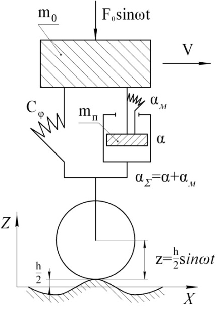
To solve this problem and provide the most detailed picture of the dynamic processes occurring in adaptive torsion suspension, formulated requirements to the developed calculation scheme and of the elaborated mathematical model, describing the damping characteristics of such a device.At the first stage, to assess the efficiency of adaptive torsion spring suspension, with respect to the jaw cart trunk or industrial locomotive (Fig. 1) were carried out preliminary calculations of the basic parameters of the proposed technical solution on the basis of the adopted scheme (Fig. 2).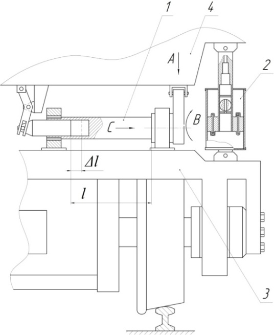 | Figure 1. Adaptive torsion spring suspension locomotive |
 | Figure 2. The calculation scheme of the torsion spring suspension |
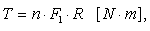
When forming of the mathematical model, according to a design diagram (Fig.2), used the equations of dynamics, theory of elasticity and hydromechanics. As the base of the calculation of the ratio was adopted by the equation of motion of a concentrated mass m0, which for the cases of power, kinematic and mixed excitation is of the form: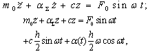
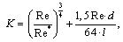
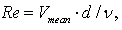
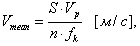
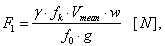
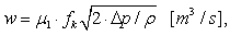
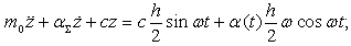 In this case, the damping factor α∑, depending on the hydraulic resistance in the channel, fluid viscosity, flow turbulence, as well as the relevant parameters, characterizing the working fluid in the throttle channels adaptive hydro-mechanical shock absorbers were defined in the following dependencies:
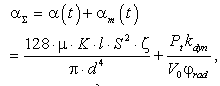 | (1) |
 | (2) |
 | (3) |
 | (4) |
 | (5) |
 | (6) |
 | (7) |
 | (8) |
 | (9) |
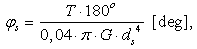
As a result of calculations performed for the locomotive 2TE10L were identified piston diameter DP = 80 mm, the diameter of the butterfly channel dК = 1.5 mm, number of channels n = 4, stem diameter dS = 20 mm, hydro-mechanical damping factor α∑ = 374.8 N·s/cm, the force of resistance to the movement of the piston R∑ = 206,96 N.For pre-practical calculation of a torsion spring suspension used approximate method of determining the equivalent damping ratios proposed W. Kirpichew and further developed I. Chelnokow. In this case used the following differential equation and is included in the parameters describing the fluctuations of the concentrated masses on the springs in the form of: | (10) |
 | (11) |
 | (12) |
As a result, were pre-installed with the most important geometric characteristics of the proposed adaptive torsion springs, designed just for jaw cart above mentioned locomotive 2TE10L. In this case it is considered, that the rod of the torsion springs made of steel 65С2ВА GOST 14959-79, and its diameter is equal to dt = 60 mm. When you change the length of the working area, for example, from 600 mm in the statics of up to 550 mm under dynamic loading changing the torsional stiffness of the torsion increased in 1.6 times and amounts to, respectively, the cs = 1127.6 N/mm and cd = 1805 N/mm, which, in the end, allows you to reduce the movement of the crew part of the locomotive with Δs = 47 mm to Δd = 36.7 mm. For the redetermined settlement, characterizing the smoothness of the locomotive 2TE10L, equipped with the technical solutions, and the study of oscillation and force loading its chassis is designed dynamic calculation scheme on the basis of elastic-plastic model Voigt-Kelvin (figure 3).Under the Сφ provided torsional stiffness of the torsion springs, and under the α∑ - total damping factor of hydromechanical shock absorbers.At drawing up of the mathematical model uses the following assumptions:1. Not taken into account bending oscillations of the rod, and other parts of hydromechanical damper.2. Coefficient of friction of mating surfaces is taken constant.3. The law of excitement due to the irregularities of the micro - and macro-profile conditional pavement changes in time according to the harmonic law.4. Is not taken into account the gyroscopic effect of a rotating mass of wheels, as well as air resistance when its translational motion.5. The processes occurring in the hydromechanical damper, believe isothermal to the specified coefficients of viscosity of the working body.6. To reflect the movement of the piston and the rod relative to the frame with the longitudinal oscillations applied inverse form of the assignment of coordinates, and with torsional direct.7. Vectors of dry friction forces in the forward kinematic pair the piston - working cylinder were heading in the opposite direction relative to the coordinate system.8. The movement of the locomotive is on the straight stretch of road without bias.9. Profile path under the two wheels of each wheelset is the same.For a description of the rectilinear motion of the locomotive bogie choose the following generalized coordinates the movement's centre of gravity of the locomotive in the direction of motion; vertical movement of the centre of gravity Z locomotive; angular displacement φ crew of the locomotive in the vertical plane with respect to the transversal axis, passing through its center of gravity. The systems of generalized coordinates accept the Cartesian lefts. | Figure 3. The calculation scheme of the locomotive bogie 2TE10L |
Using the technique of linearization, which gives opportunity to carry out, both quality and quantitative study of nonlinear systems of suspension with a high enough for practical tasks degree of accuracy, we write the equation of the oscillations of the crew part of the locomotive: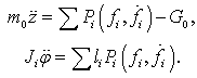 | (13) |
The force of Pi can be presented in the form of two forces: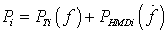 | (14) |
wherePTi – force caused by the movement of the leaf suspension and characterized by the torsional rigidity of the shaft torsion;PHMDi – force caused by the resistance of hydromechanical damper.It is seen that the forces of Pi, attached to the wheels and motors unit of irregularities way, can be expressed in terms of generalized coordinates of φ, z, y, and the frequency of the external excitation p = 2πυ/α, where α is a dimensionless variable associated with the time t is a linear dependence of α=pt.Then equation (1) can be written as follows: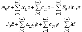 | (15) |
 | (16) |
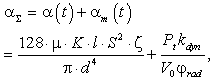
Analyzing the formula (16) we see that the variable total hydro-mechanical damping factor αΣ of the proposed hydromechanical damper will depend on the hydraulic resistance in the channel, the viscosity of the working fluid and flow turbulence α (t) arising in the channels of the piston and the rod, as well as from mechanical αm (t), which are characterized by the torsional stiffness СφS variable cross-section of the piston rod. Such an integrated its constructive characteristics allows to efficiently in the automatic mode and in a wide range of impact of the dynamic loadings arising in spring suspension rail crew, to produce vibration dampening the crew part of the locomotive.The General solution of equations (15) looking for in the form of: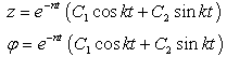 | (17) |
Solving equation (15) we can determine the amplitude of the steady-state oscillations of spring mass z0 and the amplitude of φ0, respectively, on dependencies: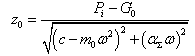
 | (18) |
For the resonance modes depending have the form: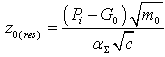 | (19) |
For the decision of ordinary differential equations describing the fluctuations of the locomotive bogie, used widely professional applied mathematical package MATLAB 6.5., designed for the solution of practical engineering problems.Construction of the model includes the solution of differential equations for the serial spring suspension of the above locomotive and the perspective of a torsion under the same initial conditions. For the series production of springs of the suspension of the locomotive equations describing the forced vibrations, have the form: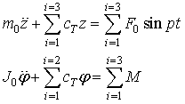 | (20) |
and for torsion, as it was mentioned above, according to equation (15).The initial conditions: For clarity performed analytical and numerical solution of the presented differential equations. The analytical solution obtained when using dsolve built-in package Tool Box Symbolic Math, the input arguments, which are the line to the equation, boundary conditions, if any, and the independent variable for which is the default t.Numerical solution of a set of differential equations with initial conditions, i.e., the Cauchy problem, carried out with the help of built-in functions of MatLab, called solvers. For the above equations used solver ode45, which is based on the method of Runge-Kutta method of the fourth and fifth order of accuracy. The input arguments solvers are: the name of the file functions in apostrophes, vector with an initial and a final time value observations of the movements and the vector of initial conditions. Output argument two: the vector of values of time and a matrix of values of unknown functions. The values of the functions are located at the columns of the matrix in the first column is the value of the function, in the second - its first derivative. Scheme of location of the numerical solution consists of the following stages:1. Adjusting the differential equation to a system of differential equations of the first order. For the presented equations were obtained the following systems:- for the series production of springs of the suspension:
 - for the perspective torsion suspension:
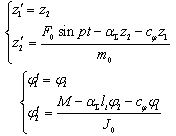 2. Writing a special file of functions for the system of equations obtained. File-function must have two input arguments: the variable t, which is the differentiation, and the vector, the amount of which is equal to the number of unknown functions of the system. File-function for the initial equations (15) and (20) eq_serZ, eq_serFI and eq_modZ, eq_modFI are in the Listings.3. Call solver ode45.4. Visualization of the obtained results.An analytical solution of the differential equations (20) after the start of the file-program solv_serial has the form presented in figure 4.An analytical solution of the equations (15) split into 2 parts: figure 5, a - solution for Z, and figure 5, b - a solution for φ. From figure 6 we see that when using the serial spring suspension vertical movement lie in the range from 0.05 to 0.12 m, while the use of adaptive spring suspension they do not exceed 0.02 m. It is clear that the numerical value of the amplitude Z at the initial moment of time reaches of 0.055 m, but within 1.5 seconds it sharply decreases to the value of 0.02 m. A similar pattern is visible and the angular fluctuations of the body. When using the serial suspension amplitude of the angular oscillations of φ is constant on all the time interval in 10 seconds, and reaches a value of 0.15 rad. However, in the case of the use of adaptive spring suspension amplitude of such movements shall be no greater than 0.01 rad, starting from 4-th of a second movement of the locomotive, although at the initial moment of time they are large in size - 0.15 rad.
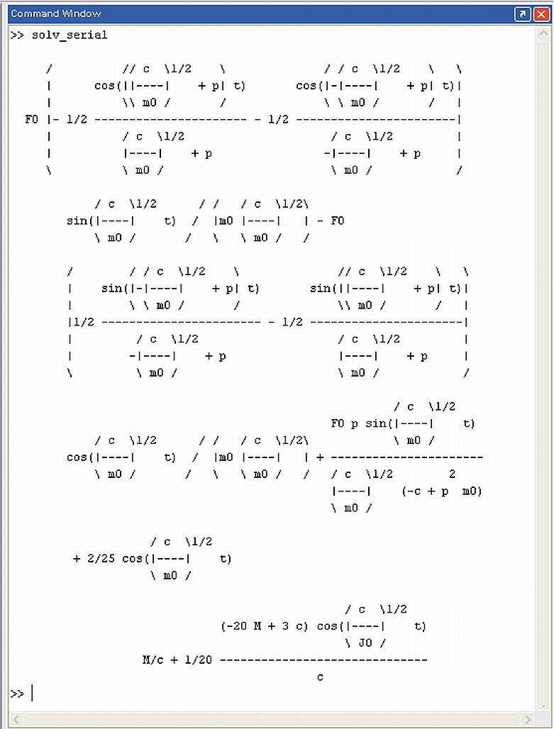 | Figure 4. An analytical solution of the equations describing the forced vibrations of serial suspension |
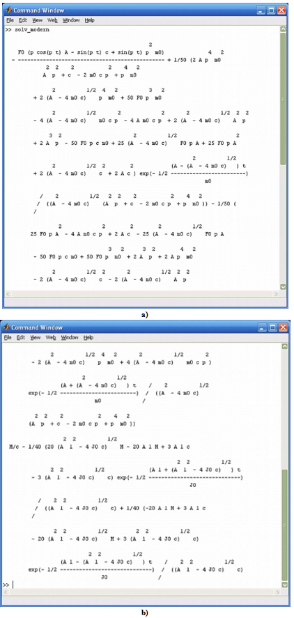 | Figure 5. An analytical solution of the equations describing the forced oscillations of the torsion suspension |
The result of the numerical solution of displayed in the graphs presented in figure 6.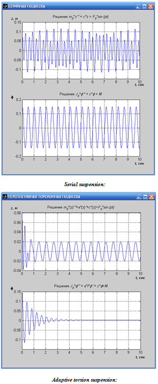 | Figure. 6. Amplitude-frequency characteristics of vertical and angular fluctuations |
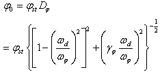
After the solution of the differential equations are constructed, amplitude-frequency characteristics for a torsion spring suspension. The formula for the amplitude of forced oscillations, has the form: Taking into account the dynamic factor built a family of curves, the host various values of the ratios of n/p. The family of such curves presented in figure 7. This graph of the family of curves constructed for the perspective adaptive torsion suspension, shows that at the approach of the frequency perturbations ω to the frequency of oscillation of the p, dynamic factor increases, and the maximum amplitude of oscillation is achieved approximately in respect of ω/p=1. At the same time from 5 presented in figure 7 plots the most removed from the resonance zone chart with the ratio n/p=0.6 and maximum coefficient of dynamic equal to 1.7, which is characteristic of the proposed design of adaptive torsion spring suspension with adaptive damping elements at a total coefficient of damping αΣ=420,0 kN∙s/m. While the decline in the last possible input suspension in resonance.To determine the resonance mode of the amplitude of steady-state oscillations was used by the known method and then was used by the file-program rezonans, showing the dependence of the resonance amplitudes from the stiffness of the suspension in various types of dithering. The graphs obtained are shown in figure 8.
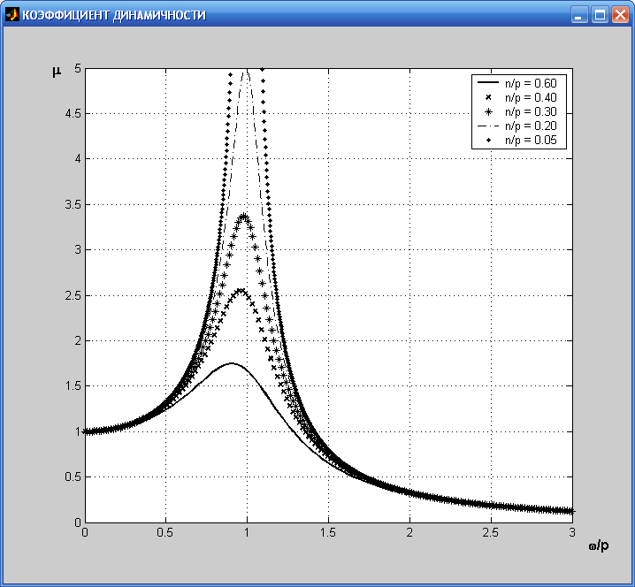 | Figure 7. The family of curves for the dynamic factor of μ |
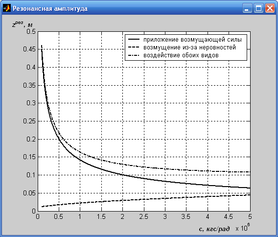 | Figure 8. Dependence of the amplitudes of resonance from the stiffness of the suspension |
The analysis of the diagrams, characterizing the resonant modes of oscillation cart  and
and  depending on the torsional stiffness of the proposed torsion suspension, shows that the smallest fluctuations are obtained in the case when the torsional stiffness of the torsion spring suspension is in bounds of the order of 3,5∙107 up to 5∙107 N/rad.For a more complete study of the oscillation process of the locomotive bogie with use of the developed models were calculated basic parameters characterizing the dynamics of motion of a locomotive at different values of F0, αΣ and сφ, which, in particular reflect the change during the time interval in 10 seconds with the vertical movement of the body Z and the speed of this movement Z’. As a result of such calculations show that using the proposed design of adaptive torsion suspension of amplitude of oscillations of the body and the speed of its movement in the vertical plane much lower than the cart, equipped with leaf springs.To confirm the correctness of the calculation was developed method benchmark test of experimental studies of the proposed design of perspective suspension.The basic scheme of the test stand, shown in figure 9, represents the elastic rod, motionless fixed in support B and mobile, with the help of splines, in support A, which are established on the table hydraulic press, creating effort of compression of up to 160 kN.
 were calculated rational parameters and characteristics of the perspective of adaptive torsion suspension, with respect to locomotives 2TE10L, which amounted to diameter equal to dt = 69,5 mm, length of the working area of the rod of the torsion 637 mm with torsional stiffness C = 1213,0 N/mm. Such values of a good agreement with previously obtained estimates.
4. The Results
As a result of the bench experimental research, as well as using methods of mathematical modeling, received rational geometric and жесткостные characteristics of a number of torsions, which can be widely used in various models of the rolling stock. According to the results of the research proposed a number of technical solutions, created at the level of 8 inventions of the Russian Federation, which are modifications of the above construction, and in each case, that permits to use them not only in the designs of locomotives, but also passenger and freight rolling stock. For such structures as the calculations on the substantiation of their rational kinematic and geometric parameters.With account of the above-mentioned, the carried out researches have allowed to expand the well-known classification of the running parts of the rolling stock, as shown in figure 10.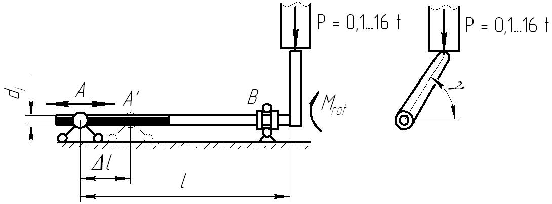 | Figure 9. The basic scheme of the test stand |
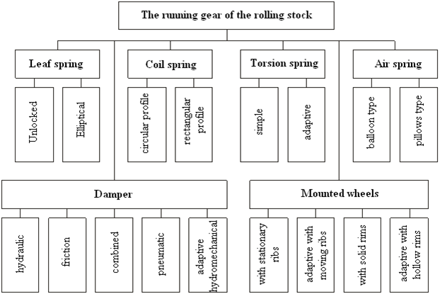 | Figure 10. The classification of the running gear of the rolling stock |
5. Conclusions
Developed by promising adaptive torsion suspension, designed for the main and industrial locomotives, including adaptive hydro-mechanical dampers, established on the level of inventions (RU2427737 and a positive decision of FIPS from 25.04.2012, according to the application №2011121597/11), schematic diagram of which is shown in Fig. 1 allows you to: firstly, to reduce consumption of metal chassis of the rolling stock, secondly, to simplify the design of the spring suspension, third, to increase the maintainability of it and in the fourth increase the smoothness of the crew at the expense of its ability in the automatic mode effectively mitigate any dynamic components of the loads caused by the irregularities of the way when the motion of the rolling stock.The results of the research are recommended both domestic and foreign scientific research institutes, design and production structures heavy machinery for further study and elaboration of proposed constructions of adaptive torsion spring suspension with a view to the possible introduction of it in practice.
References
| [1] | A.D. Derbaremdiker, “Hydraulic shock-absorbers of cars”, 235, 1969. |
| [2] | W.N. Iwanov, “Structure and dynamics of diesel locomotives”, 260, 1974. |
| [3] | I.I. Chelnokov etc. “Quenchers of fluctuations of cars”, 165, 1963. |
| [4] | I.M. Babakov, “Theory of fluctuations”, 1968. |
| [5] | W.I. Feodos’ev “Resistance of materials”, 326, 1980. |
| [6] | A.A. Uginchus, E.A. Chugaeva “Hydraulics”, 350, 1985. |
| [7] | Savin L.A., Slivinskiy E.V. Element base of hook-on vehicles (Monograph). – Oroyl: Oroyl STU, 2008. – 296 pages. |
| [8] | E.V. Slivinskiy, L.A. Savin, S.J. Radin “Ways of improving the chassis of vehicles” (Monograph). Yelets: Yelets SU name I.A. Bunin, 2009. – 240 pages. |
| [9] | Hydraulic damper. Building and road machinery. - 2010. - №9. - S. 62. Technique - Invention and rationalization. Patent case. |
| [10] | Slivinskiy E.V. Modernization and ways of improvement of trains of vehicles. LAP LAMBERT Academik Publishing CmbH & Co KG Dudweiler Landstr (monograph). 99, 66123 Saarbrucken, Germany 2011. 471 p. |
| [11] | Slivinskiy E.V., Klimov D.N., Mitina T.E., Suzdal’skaya E.A. Promising torsion spring suspension for main and industrial diesel locomotives with pedestal bogie. XV international scientific-technical conference «Fundamental problems of engineering and technology»- «Technology - 2012» June 5-8, Oroyl, 2012. |
| [12] | Slivinskiy E.V., Savin L.A., Klimov D.N. Adaptive suspension for locomotives. Collection of works «The Best engineering-technical personnel of Russia». Moskow, www.nntk2011.ru |
| [13] | Slivinskiy E.V., Savin L.A., Klimov D.N., Suzdal’skaya E.A. Promising suspension for diesel locomotives with pedestal boogie. Control system of technical systems: ways and methods of research. Materials of interuniversity scientific-practical conference. YSU name I.A. Bunin. Dace. 4, 2012-240. |
| [14] | Slivinskiy E.V., Radin S.J., Klimov D.N., Gridchina I.N. Dampers for HSGT railway rolling stock. Actual problems of technical Sciences [Text]: materials of the regional scientific-practical conference. Lipetsk: Publishing house LSTU, 2011 - 155 p. |
| [15] | Slivinskiy E.V., Klimov D.N., Suzdal’skaya E.A., Gridchin D.W. Promising torsion spring suspension for main and industrial diesel locomotives. Lipetsk regional specialized seminar «School of young scientists» the problems of technical Sciences: Collection of works. - Lipetsk, LSTU, 2011. -135 p. |
| [16] | Slivinskiy E.V., Savin L.A., Radin S.J., Klimov D.N. To the assessment of the smooth progress of passenger cars equipped with the spring suspension promising hydraulic damper fluctuations. Management system, technical systems: ways and methods of research. Materials of interuniversityscientific-practical conference. YSU name I.A. Bunin. Num .3, 2011-230 p. |
| [17] | Slivinskiy E.V., Savin L.A., Radin S.J., Klimov D.N. To the question of modernization of the balancer suspension diesel locomotives CHME2. Management system, technical systems: ways and methods of research. Materials of interuniversity scientific-practical conference. YSU name I.A. Bunin. Num. 3, 2011-235 p. |
| [18] | Slivinskiy E.V., Savin L.A., Radin S.J., Klimov D.N. Development of technical measures to improve the smooth running of passenger cars. ΙΙ all-Russian scientific- methodical conference «basic principles of design and details of machines - ΧΧΙ century». Oryol: Oryol STU, 2010. – 365 p. |
| [19] | Slivinskiy E.V., Savin L.A., Klimov D.N. Suspension locomotives. Shock-and-vibration systems, machines and technologies: materials IV international scientific Symposium. - Oryol: Oryol STU, 2010. - 384 p. |
 Abstract
 Reference
 Full-Text PDF
 Full-Text HTML