-
Paper Information
- Paper Submission
-
Journal Information
- About This Journal
- Editorial Board
- Current Issue
- Archive
- Author Guidelines
- Contact Us
Journal of Mechanical Engineering and Automation
p-ISSN: 2163-2405 e-ISSN: 2163-2413
2012; 2(5): 85-90
doi:10.5923/j.jmea.20120205.01

Output Force Enhancement of Finger-type Manipulator by Adopting Brushless DC Motors for Sliding Actuation
 Abstract
 Reference
 Full-Text PDF
 Full-text HTML
Young June Shin , Ho Ju Lee , Kyung-Soo Kim , Soohyun Kim
Department of Mechanical Engineering, KAIST, Daejeon, 305-701, Republic of Korea
Correspondence to: Kyung-Soo Kim , Department of Mechanical Engineering, KAIST, Daejeon, 305-701, Republic of Korea.
| Email: |  |
Copyright © 2012 Scientific & Academic Publishing. All Rights Reserved.
This work is licensed under the Creative Commons Attribution International License (CC BY).
http://creativecommons.org/licenses/by/4.0/

In this paper, we newly develop a finger-type manipulator driven by the sliding actuation with miniaturized brushless DC (BLDC) motors. The mechanism allows the usage of the maximal capacity of actuators by employing the distributed actuation principle while maintaining the small size. Thanks to the high thrust force of the BLDC motors, the maximum fingertip force of the developed robot finger is remarkably enhanced. Through experimentation, the fingertip force of the proposed robot finger is assessed and compared with the former version with the ultrasonic motors.
Keywords: Distributed Actuation, Sliding Actuation, Robot Finger, High Fingertip Force, Robot Manipulator
Cite this paper: Young June Shin , Ho Ju Lee , Kyung-Soo Kim , Soohyun Kim , Output Force Enhancement of Finger-type Manipulator by Adopting Brushless DC Motors for Sliding Actuation, Journal of Mechanical Engineering and Automation, Vol. 2 No. 5, 2012, pp. 85-90. doi: 10.5923/j.jmea.20120205.01.
Article Outline
1. Introduction
- The hand is one of the most important parts of the human body, and the high functionality of hands allows a number of delicate tasks, such as the grasp, lifting, or manipulation of objects. The uniqueness of human hands has been recognized and discussed extensively in the literature [1-3]. Likewise, a dexterous robot hand is necessary for various applications such as the end-effector of industrial manipulators, prosthetics, surgical robots, and surveillance robots.Artificial robot hands commonly adopt electrically geared motors for actuation. For example, DLR-HIT hand II [7], KH hand [8], and the smart hand [9] utilize several electrical motors for dexterous motions together with complicated torque transmission mechanisms.In [6], the excessive weight of a robot hand is one of the main hindrances for use as a prosthetic device. To overcome the disadvantages of the robot hands driven by electrical motors, light weight actuators, such as a shape memory alloy (SMA) wire, can be adopted for prosthetic hands [10, 11]. An SMA wire has a large power density, but the absolute contraction force may not be sufficient to generate a large grasping force. Also, the slow response due to the heating and cooling processes, and low strain [11] is the typical drawbacks of SMA wires.Robot hands using pneumatic muscle actuators have been proposed in [12-14]. These robot hands may generate larger power per weight than the SMA wire based robot hands do. However, for generating a large grasping force, a large capacity compressor should be employed to produce high pressure. Recently, in [16], a DC motor and an SMA wire were combined for the robot hand. In [15], the robot finger utilizing the stacked EAP actuator is also proposed.Despite efforts to develop anthropomorphic hands, the performance, such as the grasping force with respect to the size or weight, may not be satisfactory today. To address this problem, the distributed (or sliding) actuation principle was proposed in [4]. It utilizes the spatial freedom of the actuation location as an additional design parameter to maximize the fingertip force of the robot finger. The fingertip force was shown to be widely adjustable by only controlling the positions of the sliders.However, the use of ultrasonic motors leads to absolutely small fingertip force. Motivated by the weakness of [4], in this paper, to enhance the maximum fingertip force, we newly developed a robot finger driven by tiny BLDC motors based on the distributed actuation mechanism.By optimizing the positions of the sliders, the fingertip force can be remarkably increased. To verify the effectiveness of the idea, simulation and experiments are performed. The paper is organized as follows. In Section II, the distributed actuation principle is shortly revisited and the BLDC motor driven manipulator is newly introduced. Section III is devoted to numerically assessing the performance of the developed robot finger. Section IV describes the experimental results. Finally, conclusions are drawn in Section V.
2. Development of Robot Finger
2.1. Distributed Actuation Mechanism
- Based on the observations of human finger muscles, the distributed actuation mechanism was proposed in [4]. The muscles distributed on each phalange of a finger play an important role of multiple actuations for bending or extending the finger. To abstract the features of muscles in a human finger, the mechanism is effectively implemented as shown in Fig. 1(a). A slider can move along a link, and two sliders at each joint are connected by a connecting rod at each joint. Therefore, by changing the positions of the sliders, the desired join tangle can be achieved, as shown in Fig. 1(b). Also, in particular, the sliders may be relocated along the links while the joint angle is fixed as shown in Fig. 1(c). It would give a different joint torque. This allows an additional design factor to optimize the joint torque at each joint. This feature was verified by the simulation and experiments in [4], in which an earlier version of finger-type manipulator I (FM I) was reported. The structure of FM I adopting tiny ultrasonic motors results in a robot finger design of small size and light weight. However, the fingertip force of FM I is very small due to the small thrust forces of ultrasonic motors.
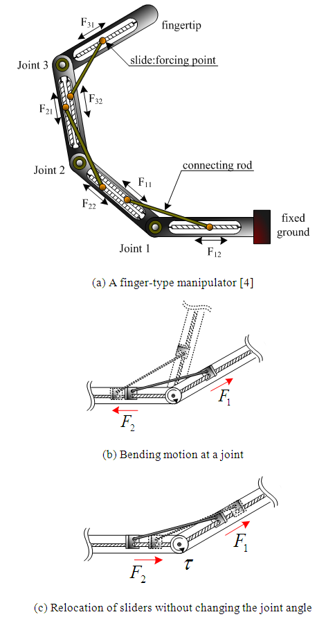 | Figure 1. A concept of a distributed actuation mechanism |
2.2. BLDC Motor-based Design
- To overcome the shortcoming of FM I, we newly designed a finger-type manipulator, the so-called FM II, by embedding the BLDC motors, as shown in Fig. 2(a) [5]. FM II consists of four links with three joints. The linear motions of sliders can be achieved by the miniaturized BLDC motors with lead screws, except for the slider of Link 3. Note that, due to the short length of Link 3, the slider is wired to and driven by the motor at Link 0. Also, by using a tensile spring, the slider can be pushed away. The connecting rods are for connecting two sliders around a joint. The motor has a gear with a ratio of 1:125, a diameter of 6 mm, and a maximum torque of 0.0190 Nm.
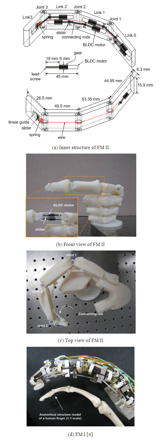 | Figure 2. Comparison of two developed robot fingers |
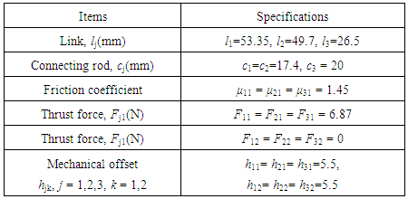
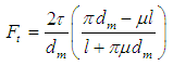 Where l is the lead pitch, dm is the mean diameter of the lead screw, μ is the Coulomb friction coefficient, and t is the motor torque. With the values such that l = 1mm, dm = 3mm, μ = 1.45, and t = 0.0190 Nm, the maximal thrust force is calculated with 6.87N.For the exterior shape similar to a human finger, the three-dimensional profiles (STL model) for each phalange of the middle finger bone model were obtained by using the 3D laser scanning device (Vivid 9i, Konica Minolta Sensing, Inc.). Then, the data was converted to a solid model by using 3-D CAD programs (Rapid Form, CATIA P3V5R17). Then, using a rapid prototype machine (Object Eden 330), we manufactured a robot finger frame and the components, such as the connecting rods and the sliders, as shown in Figs. 2(b) and (c). The design parameters for FM II are summarized in Table 1 in comparison to FM I (shown in Fig. 2(d)). Because of the usage of BLDC motors, the weight of FM II was increased, but the thrust force of sliders was remarkably enhanced by 12.8 times. Note that the movable range of the sliders is restricted within 12 mm, which allows a joint angle between 0° to 90°.
|

3. Assessment of Finger-Type Manipulator II
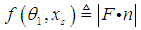
- In this section, the fingertip force of FM II is assessed by simulations. As shown in Fig. 3, the fingertip force is defined in a normal direction and can be computed by
 | (1) |
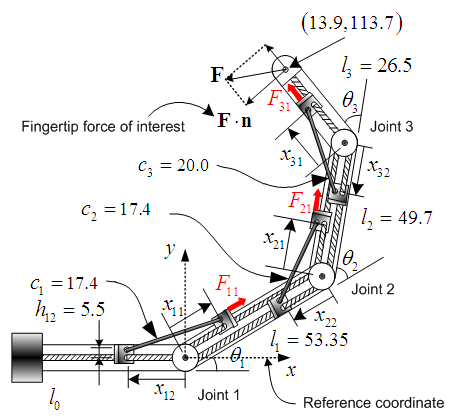 | Figure 3. Notations of common parameters for simulation (all in the mm units) |
|
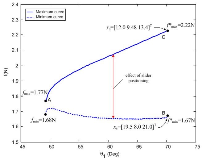 | Figure 4. Fingertip force of FM II depending on θj and xs (A, B, and C denotes the cases that will be tested experimentally |
4. Experiments
4.1. Description of Experiments
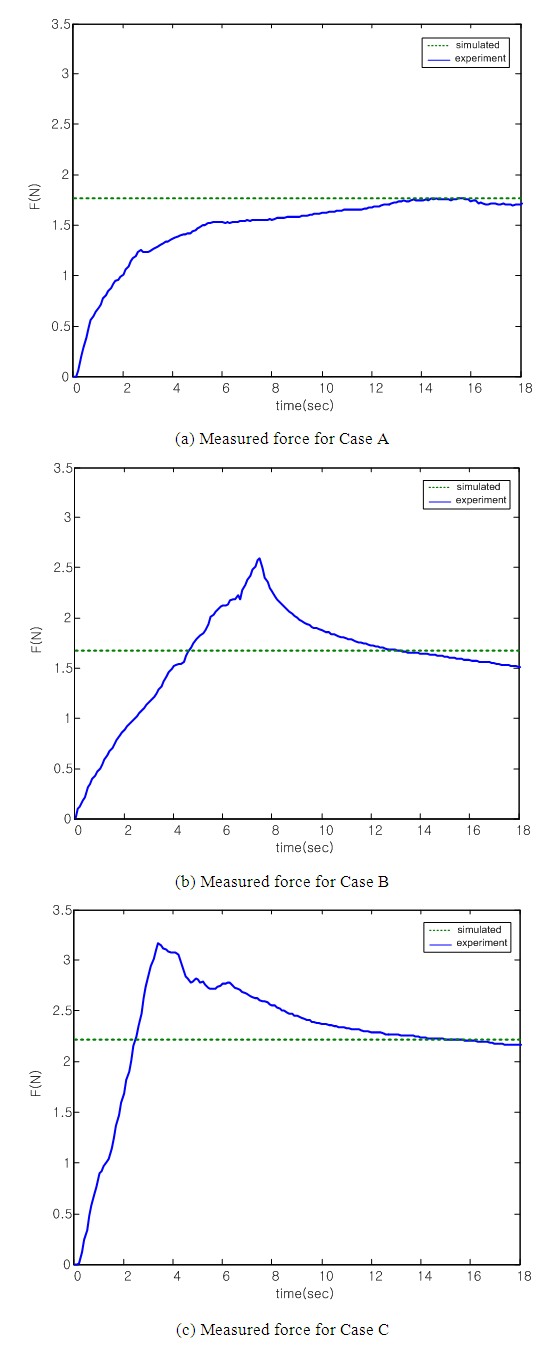
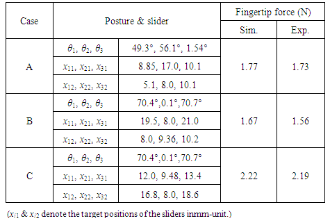
- To verify the performance of FM II having sliders with high thrust forces, we measured the fingertip force under the experimental environment as shown in Fig. 5. Given a target position, (13.9, 113.7) mm, we selected three different cases, A, B, and C, as marked in Fig. 4 and measured the output forces. The specific conditions for three cases are summarized in Table 3. The fingertip force was measured by a load cell (BCL1kgf, CAS Corp.). To measure the fingertip force, first, the fingertip was located by a position feedback control at the target position. Then, the position control was turned off, and the feed forward control with constant thrust force was turned on at the target position.
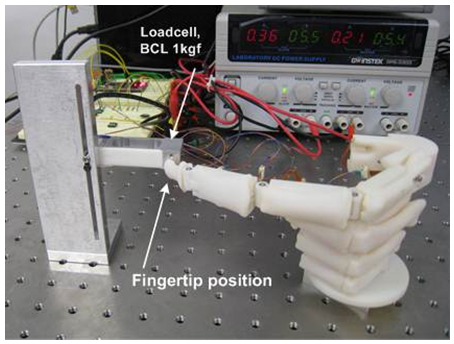 | Figure 5. Experimental setup for measurement of fingertip force |
4.2. Experimental Results and Discussions
- The measured forces are shown in Fig. 6, and the averaged fingertip forces for 3 seconds between 15 sec and 18 sec are summarized in Table 3. It is noted that the measured fingertip forces approximately match the simulation results.
 | Figure 6. Experimental results for measurement of fingertip force |
|
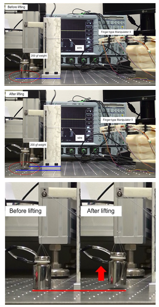 | Figure 7. Demonstration of fingertip force enhancement by lifting a weight of 200 gf. Before lifting (top), after lifting (middle) |
|
5. Conclusions
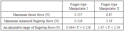
- In this paper, an improved version of a finger-type manipulator was newly proposed. By implementing the distributed actuation principle with miniaturized BLDC motors, we achieved a high fingertip force while maintaining the light structure. The newly developed robot finger merely weights 33.4 gf, but produces a maximum fingertip force of 2.19 N. Thanks to the large thrust forces of the sliders, the fingertip force increases remarkably compared with the former version. By simulation and experiments, the effect of the distributed actuation principle and the feasibility of the proposed mechanism were verified.
APPENDIX
- Derivation of Torque at Joints and Fingertip ForceLet us consider the torques at the joints as follows:
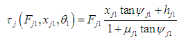 | (A.1) |
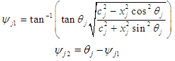
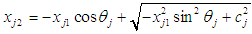 for j = 1,2,3. Under the joint torques presented above, the fingertip force can be described by
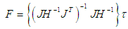 | (A.2) |
ACKNOWLEDGEMENTS
- This work was supported by the Unmanned Technology Research Center, Korea Advanced Institute of Science and Technology, originally funded by the Defense Acquisition Program Administration, Agency for Defense Development.