Hua Qiu 1, Yong Yue 2, Chao Lin 3, Kai Cheng 4
1Department of Mechanical Engineering, Faculty of Engineering, Kyushu Sangyo University, 2-3-1 Matsukadai, Higashi-ku, Fukuoka City, 813-8503, Japan
2Department of Computing and Information Systems, University of Bedfordshire, Park Square, Luton LU1 3JU, United Kingdom
3State Key Laboratory of Mechanical Transmission, Chongqing University, Shapingba, Chongqing, 400044, People’s Republic of China
4Advanced Manufacturing and Enterprise Engineering Department, School of Engineering and Design, Brunel University, Uxbridge, Middlesex UB8 3PH, United Kingdom
Correspondence to: Yong Yue , Department of Computing and Information Systems, University of Bedfordshire, Park Square, Luton LU1 3JU, United Kingdom.
| Email: |  |
Copyright © 2012 Scientific & Academic Publishing. All Rights Reserved.
Abstract
The paper presents research on the improvements over an autonomous non-contact device with a vertical spindle for free form measurement which the authors developed previously. The fundamental ideas in the previous work include combining two displacement sensors with a servo motor, keeping the position of the sensor to directly measure the surface at the central value of the sensor’s measuring range by controlling the motor rotation and performing scanning motions with NC functions of a MC. The inspection is entirely independent of the NC apparatus of the MC. Taking into account both the measurement accuracy and efficiency, three major improvements have been made retaining the advantages of the device. These improvements include 1) introducing a new sensing method for reference position along a scanning line to separate the reference position detection from the contour profile measurement, 2) accepting an AC servo motor controlled by a speed rule to raise the capability of autonomous movement following the contour profile to be measured, and 3) adopting a new laser displacement detector to widen the applicable range for both the shape and material of the surface to be measured. To assess the performance of the improved device, verification experiments are carried out on a machining center with several samples made of different materials. The experiment results demonstrate the effectiveness of the improvements made on the device.
Keywords:
Autonomous Form Measurement, Free Form Surface, Performance Improvement, Machining Center, Measuring Device
1. Introduction
How to create a geometric model from measured point data on unknown component surfaces, such as those on clay models, and art and craft products, is one of the most important applications in reverse engineering. This has attracted the attention from more and more researchers and engineers in recent years. There are numerous efforts being put into the research and development[1-4]. As the first step of this problem, the acquiring method of measurement data not only determines the precision and efficiency of the inspecting operation but also directly affects the quality and reliability of the ultimate geometric model created. Therefore, it is essential and necessary to develop an accurate,efficient and convenient data acquisition technique.At present, coordinate measuring machines (CMM) are widely used for precise measurement of surface profiles in unknown forms in industrial practice. As an expensive machine, the CMM usually provides relatively accurate and reliable measurement results. However, using CMMs cannot be considered the best choice for such jobs. One of the main reasons is the touch trigger probe, which is accepted as a touch sensor in most CMMs, results in a low measuring efficiency and requires an offsetting operation for obtaining the surface profile from the measurement data. The offsetting operation is sometimes very difficult for a measured profile in unknown forms[1-9]. Automated laser scanning measurement is an expected technique as it is efficient for inspecting complex profiles. However, because several difficult problems such as automatic planning of scanning line and measurement accuracy have not been solved completely, research efforts so far have been focused on applying the technique to inspect profiles in a known form, for example, a contour defined by a CAD model, rather than those in unknown forms[10-15]. Furthermore, with the progress of micro/nano metrology, some ultra-precision 3D contour form measuring devices are commercially available for inspecting the surfaces of precision products such as aspheric lenses and semiconductor wafers[16-18]. These devices offer excellent performance for inspection purpose. However, the high cost and strict working environment limit their applications as general industrial measuring devices.With the progress of motion accuracy of CNC machine tools, in recent years, several methods have been developed to inspect the form error of a machined workpiece on CNC machine tools[19-22]. The basic idea of these methods is a comparative inspection between the practical surface and the ideal surface for a workpiece. An adequate and inexpensive sensor is normally located on the machine tool and moved with the same NC program used to machine the workpiece, so the sensor is able to judge the contour form error of the practical surface in light of the ideal surface. Therefore, these methods can only be applied in a case where the geometric model for the measured contour has been pre-determined. Furthermore, Miyoshi et al[23,24] and Chang and Lin[25] developed an approach respectively, which involves a controller to CNC machine tool movement and a scanning sensor, for inspecting contours in unknown forms on a machining center (MC). Because this approach is based on the principle of open CNC apparatus, it requires a high level of knowledge on NC technologies for the applications.Prior to this research, the authors had proposed a new principle which is relatively simple and efficient for measuring free form surfaces on a MC[26]. The fundamental ideas include combining two displacement sensors with a servo motor, keeping the position of the sensor to directly measure surface at the central value of the sensor’s measuring range by controlling the motor rotation and performing scanning motions with NC functions of the MC. The inspection operation is entirely independent of the NC apparatus of the MC. Both the control rule and the NC programming are relatively simple, and the knowledge requirement on NC technologies is minimized. Based on the principle, a non-contact prototype measuring device was produced (called the old device in this paper) for the MC with a vertical spindle and its performance examined by measuring different samples[26].In this paper, further development and improvement are presented towards practical applications of the device. Section 2 describes the problems with the application of the old device and then the corresponding development and improvement performed in detail. Section 3 presents several examples of form measurement by applying the improved device, called the new device in this paper, on a MC for the samples made of different materials. The experiment results sufficiently demonstrate the effectiveness of the new device and improvements. Section 4 draws conclusions on the work presented.
2. The Problems with Old Measuring Device and the Improvements
2.1. Problems with the Old Measuring Device
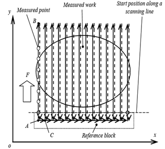
Fig. 1 shows a schematic diagram of the old measuring device. The coordinate frame, o-xyz, is set at the table of MC and each axis is parallel to the corresponding one of the machine coordinate frame of the MC respectively. The device base is fixed on the spindle of the MC by fitting a taper surface into the taper hole of the spindle. A ball screw that is directly driven by a stepping motor is fixed on the base. The screw axis is parallel to the spindle axis, i.e. the z axis. With the screw rotation, the screw nut built in a slider moves along the z direction. A linear encoder is separately set, i.e. the scale at the base and the head at the slider. A laser displacement detector whose sensing direction is parallel to the z direction is fixed on the slider, too. While a measurement is processed, the output of the laser detector is transferred to a personal computer at each sampling time through an RS-232 interface and then the computer sends a movement command to the motor driver via a motor control board. The command is decided with a PTP rule, i.e. keeping the distance from the measured point to the laser detector at the central value of the detector range, as shown in Fig. 2, where t0 and t are the central value of measuring range and the output value of the laser detector respectively. At the same time, the moving displacement of the slider is detected by the linear encoder and transferred into the computer through the encoder amplifier and a counter board.In a measuring operation, a workpiece to be measured is set on the table of the MC together with a reference block. Once the distance between the spindle and the table is adjusted to a proper value, the positions of both spindle and table are fixed on the z direction. Then, the table is moved in turn along each scanning line, which is straight line parallel to the y axis, by a pre-coded NC program, as shown in Fig. 3. Because the distance from a measured point to the laser detector is always kept near the central value of the detector measuring range, the detector can automatically follow the workpiece profile and detect the point position along a scanning line. The displacement of each measured point on the z direction relative to the reference point on the block is just equal to the sum of the outputs of two sensors, i.e. the laser detector and the linear encoder. As shown in Fig. 3, the scanning is started at Point A along the y direction. Once the position of the block edge, which is set perpendicularly to the scanning direction, is detected by the laser detector, the positions of measured points on the z direction are in turn recorded at every sampling time. At the end of the scanning line, Point B, the recording is stopped and the table is turned back to Point A along the opposite direction. Then the table is fed to the start point of the next scanning line, point C, through a scanning line interval. The above process is repeated for each scanning line until the last one. For each measured point on a scanning line, the position in the x direction is the same as that of the scanning line itself, and the position in the y direction is equal to the distance from the reference block edge, i.e. scanning speed × sampling time × the order of the point.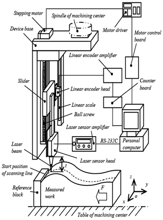 | Figure 1. Schematic diagram of the old device |
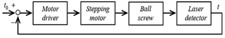 | Figure 2. Control block diagram of the stepping motor |
 | Figure 3. Scanning process of form measurement |
In the old measuring device, an incremental type of linear encoder is used and its measuring range and resolution are 120 mm and 0.1 μm respectively. A diffusion reflection type of laser displacement detector is used, and the measuring range and resolution are 30±5 mm and 0.1 μm respectively. The mass of the sensing head is 265 gram. The diameter of the laser beam is 30 μm at the central position of the measuring range. The data communication speed of the RS-232C interface is 19,200 bps. Moreover, the pitch of the used ball screw with a slight preload to remove the backlash is 1 mm. The command pulse is 500 for one revolution of the stepping motor.From the experimental results of inspecting various types of contour profiles, three major problems with the old measuring device have been identified, which need to be further improved for achieving the better performance. These problems are:(1) Sensing precision for reference position of a scanning lineThe first problem is the detecting method and precision for the reference position along a scanning line. While application of the old device, the reference position to start the data recording process is set at an edge of the reference block and directly detected by the laser displacement detector. Due to the limitation of the spot size of laser beam and the effect of the non-continuity of surface shape around an edge, the detecting precision can only achieve an order of tens of micrometer. Moreover, because the allowed data communication speed of the RS-232 interface attached in the laser detector used is quite low, the scanning movement has to be limited to a comparatively low speed to guarantee the sensing accuracy of the reference position, which results in a loss of the measuring efficiency.(2) Servo capability of the stepping motor for the autonomous following movementThe second problem is the servo capability of the stepping motor used for autonomous following movement to an inspected contour profile. Since a stopping motor controlled by a PTP rule is employed for driving the laser detector to follow the measured profile in the old device, the movement of the laser detector may become unsmooth for a surface with sudden change in shape, and further leads to the step out of the motor with respect to an excessive scanning speed. Therefore, in order to guarantee the smoothness of the autonomous following movement, a lower scanning speed is sometimes specified in the measuring operation which reduces the measuring efficiency.(3) Measurement capability of the laser displacement detectorThe third problem is the measurement capability of the laser displacement detector used in the old device. For example, a sloped surface whose normal angle with respect to the laser beam exceeds 40° or a surface made of transparent or semi-transparent material cannot be correctly measured with the detector. These limitations significantly restrict the application of the device.
2.2. Improvements for the Measuring Device
To overcome the problems mentioned above, improvements have been successfully made for the measuring device. Fig. 4 is a schematic diagram of the new measuring device. Taking the convenience of the measurement operation into consideration, the scanning direction is set parallel to the x direction of the MC used.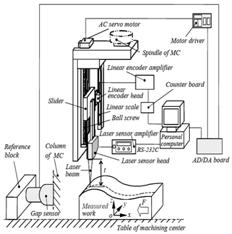 | Figure 4. Schematic diagram of the new device |
As the solution for the first problem with the old device, an electrostatic capacitive type of gap sensor with a resolution of 1 μm is employed in the new device to precisely detect the reference position along a scanning line. The gap sensor is set at the spindle column via a magnetic stand and the reference block on the table of the MC, respectively. The reference surface of the block is located perpendicularly to the scanning direction. The output of the gap sensor is transferred to the control computer via an AD converter board. In a scanning process to measure contour profile, once the gap value between the sensor and reference surface reaches a preset value, the recording process to the sampling points along a scanning line starts. The employment of the gap sensor not only improves the sensing precision of the reference position but also permits a rather higher data communication speed than RS-232 interface, so both measuring accuracy and efficiency of the whole device are significantly improved. From the results of experimental verifications, it is confirmed that, when using an accurate reference block with a surface dimension of 200 mm (length) × 40 mm (width) for sensing and a feed speed of 1,200 mm/min for scanning, the sensing precision of the reference position to a scanning line is within ± 2 μm.For the second problem, the solution is to build an AC servo motor into the new device instead of the stepping motor of the old device. A speed control rule, as shown in Fig. 5, is used with the AC motor. Based on the numeric differentiation of the position deviation of the laser detector, t-t0, with respect to the sampling time, the computer sends a speed command to the motor driver for keeping the distance from the measured point to the laser detector at the central value of the detector range via a DA converter board. From the experimental results, the effect of this improvement has been confirmed, i.e. the movement of laser detector is very smooth while a contour with sudden change in shape is inspected under a considerably high scanning speed, 600 mm/min. The rated power and speed of the AC servo motor are 30W and 3,000 min-1 respectively, and the reduction ratio of the built-in gear chain is 60.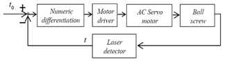 | Figure 5. Control block diagram of the AC servo motor |
The solution for the third problem is to employ a new type of laser displacement detector, Keyence LK-G30, instead of the old one. The laser detector adopts the triangle measuring principle and provides two types of measuring model, a regular reflection model and a diffusion reflection model, and it is able to inspect a surface made of transparent or semi-transparent materials. The laser detector offers a better measuring capability to an incline surface while the attached RS-232 interface allows a higher data communication speed, 115,200 bps, than the old detector. The main specifications of the new detector include 30±5 mm for the measuring range, 0.05μm for the resolution, 280 gram for the sensing head mass and 30 μm for the laser beam diameter at the central position of the measuring range.It should be mentioned that all the improvements are made while the advantages of the autonomous form measuring principle are entirely retained so the new device achieves better accuracy and efficiency. In addition, the measuring range and resolution of the linear encoder are 120 mm and 0.1 μm which are the same with the old device, and a moving speed of 50 mm/s for the laser detector can be achieved due to the rated speed of the AC servo motor.
3 Results of Verification Experiments and Discussions
In order to verify the effectiveness of the improvements, the new measuring device was used together with a vertical spindle type of MC, Washino WMC-4, to inspect the contour profiles of samples made of different materials. In all experiments, a single output of the laser detector is directly sent into the personal computer without any averaging operation.
3.1. Measuring experiments on an accurate steel ball surface
In this experiment, an accurate SUJ2 steel ball with a diameter of 50mm was used. According to the producer’s catalogue, the diameter tolerance is ±15μm, the sphericity is less than 10 μm and the surface roughness is within Ra 0.2μm (max). Considering the limitation of laser detector on the inclination of the surface to be measured, the ball was covered by an engineering wax lid so that only part of surface, where the normal angle of a point is within 68° with respect to the z axis, was exposed, as shown in Fig. 6. The diffusion reflection model was used and the experimental conditions included a sampling time of 10 ms for the motor control, a scanning speed of 60 mm/min along the x direction of the MC, and an interval of 1 mm for both the scanning lines or recorded points.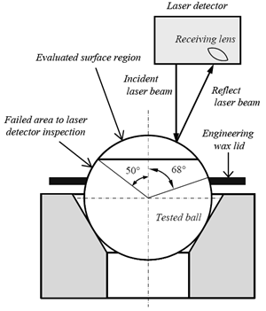 | Figure 6. Test ball setting up |
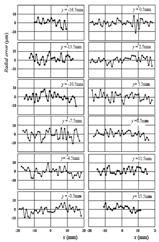
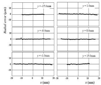
Fig. 7 illustrates the measurement result, where the coordinate frame is presented by a parallel translation to that of Fig. 4. The blank area on ball surface means where the laser detector failed to sense the surface. The blank area is located on the opposite side of the receiving lens of the laser detector relative to the incident laser beam and the normal angle of the area is lager than 52°. Therefore, 1,143 points inside the spot circled in Fig. 7, where the normal angle is within 50°, were used in the calculation of the ball radius. The result was obtained as the least square radius of 25.0010 mm and the maximum radial difference of 23.06 μm among all 1,143 points. Part of the result is drawn in Fig. 8, where a radial deviation is presented as the difference from the least square radius. As a comparison, the same part of the ball surface was also measured with a Mitsutoyo BHN 506 CMM in the same interval, 1mm × 1mm for sampling points. Part of the result is shows in Fig. 9. The least square radius is 25.0013 μm with the maximum radial difference of 4.0 μm from the CMM measuring data.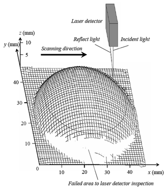 | Figure 7. Measurement result of the test ball surface |
 | Figure 8. Radial errors of the test ball by the new device |
 | Figure 9. Radial errors of the test ball by the CMM |
From Fig. 8, it can be observed that the radial difference between some neighbour points exceeds 10 μm. The radius difference is remarkable lager than that in Fig. 9 although the least square radius of ball obtained from the measuring data due to both the new device and the CMM is almost of the same value. This phenomenon is caused by the sensing characteristics of the laser displacement, i.e. some irregular error with high frequency components occurs in the measurement result by the diffusion reflection measuring model of a laser displacement detector accepting the triangle measuring principle[21]. The irregular error is derived by the local diffusion reflection property of a surface to be detected. Following the calculation method shown in Reference 21, the error value with respect to the laser detector used is limited within ±12 μm for inspecting the position of a point.The similar measurement to part of the ball surface with the old device was yet performed under the condition of sampling point interval, 1mm × 1mm, but the measured surface was located on an area where the normal angle is within 40° with respect to the laser beam, based on the characteristics of the old laser detector. Thus, there are only 805 sampling points. Fig. 10 illustrates the measuring result. In this figure, it can be observed that the average value and slope of the radial error curve along a scanning line is significantly different from those along other scanning lines. The reason is the lack of the sensing accuracy to the reference position along a scanning line with the old device. Because the variation of the reference position detected to a scanning line is uniformly put onto the position of all points on the scanning line, it makes the positions of these points used in the least square calculation for the ball radius drift from their practical positions by the variation. As a result, the average value and slope of the radial error curve along every scanning line may become different from each other. With the measured result by the new device shown in Fig. 8, however, the average value is very close to 0 and the slope is nearly horizontal for the radial error curve along each scanning line.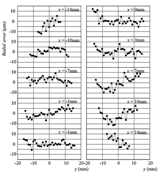 | Figure 10. Radial errors of the test ball by the old device |
Based on the result discussed above, therefore, it can be concluded that the sensing method used in the new device is very effective to improve the sensing accuracy for the reference position of scanning lines and hence raises the measuring precision of the whole device. The employment of the new laser detector makes the inspection to a more inclined surface possible than the old device. The measuring precision of the new device is governed by the characteristics of the laser detector and the value is about 20 ~ 30 μm with respect to a diffusion reflection model measurement.
3.2. Measuring experiments on a craft product surface
A plaster Hakada doll for ornamenting wall, whose surface is colourfully drawn as shown in Fig. 11, was inspected by the new device in the diffusion reflection model of the laser detector. The height in the sensing direction is about 18 mm. The sampling time was 10 ms for the motor control and the scanning speed 600 mm/min. Both interval for scanning line and recorded points were 1 mm.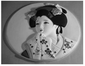 | Figure 11. Photograph of the tested Hakata doll |
 | Figure 12. Measurement result of the Hakata doll |
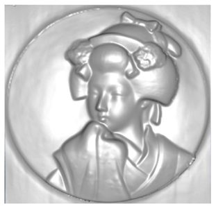 | Figure 13. CG graph of the Hakata doll surface produced from the measurement data by the new device |
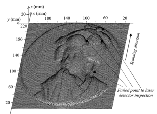
The measured result is illustrated in Fig. 12. Only 4 points marked with the black dots, where the laser detector failed to inspect, were found from a total of 41,616 measured points. Around such failed points, some small protuberances exist on the doll surface. The multiple reflection of laser beam caused by the protuberances resulted in the measuring failure of the laser detector. In drawing the measurement result, the front and rear points were directly connected to each failed point. By examining on screen along each scanning line in detail, it has been verified that the measured results were satisfactory except for these 4 failed points. As a reference, Fig. 13 illustrates a computer graphics (CG) image produced from the measured point data after removing the failed points by using CG software, Blender Ver. 4.21[27]. In the graph generation, only two functions of Blender, Subdiv.1 and Hemi light, were used without any smoothing operation. As shown in Fig. 13, the patterns on the doll surface are well presented in detail.Fig. 14 shows a CG graph produced by Blender from the measured result by the old device with the failed points removed. The measuring conditions with the old device were scanning speed of 120 mm/min, measured point interval of 2 mm × 2 mm and a total number of 12,075 measured points. Because several tens of failed points occurred inside the rectangle remarked in Fig. 14, where some local steep areas with a normal angle larger than 60° relative to the z direction existed, and were removed in the generation of the CG graph, Fig. 14 is significantly different from Figs. 11 and 13 inside the rectangle. Moreover, the inspecting experiment with a higher scanning speed, 240 mm/min, was also performed. However, in this experiment, the occurrence of rather more failed points and the step out of the stepping motor were confirmed.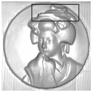 | Figure 14. CG graph of the Hakata doll surface produced from the measurement data by the old device |
From the above experiment results, it can be concluded that the adoption of the new laser displacement detector improves the measuring performance of the contour profile and the AC servo motor controlled by speed rule increases the servo capability for the measuring device effectively.
3.3. Measuring experiments on a transparent contour surface
To examine the capability of measuring a surface made of a transparent or semi-transparent material, a sculptured glass dish with a floral design was inspected with the new device. The measured surface is a square enclosed with the solid line and consists of three areas, i.e. a completely transparent glass area without any design, a semi-transparent ground glass area with a floral design and a semi-transparent glass area with a leaf design where many small protuberances exist on the surface, as shown in Fig. 15. In the inspection experiment, the regular reflection model was used with laser detector and the measuring conditions were 10 ms for sampling time of motor control, 600 mm/min for scanning speed and 1 mm for both interval of scanning line and measured point.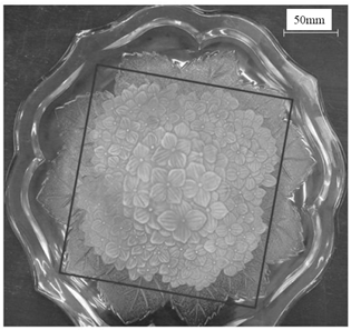 | Figure 15. Photograph of the inspected glass dish |
Fig. 16 illustrates a CG graph for a dish surface produced by Blender from the measured results through the same removing operation to the failed points as in the previous subsection. The positions of the failed points are indicated with black dots in the figure. These points mainly occur in the semi-transparent glass area with the leaf design where the protuberances on the surface result in the multiple reflection of laser beam. Whereas, no failed point were observed in the semi-transparent ground glass area and the floral designs are well presented in the graph.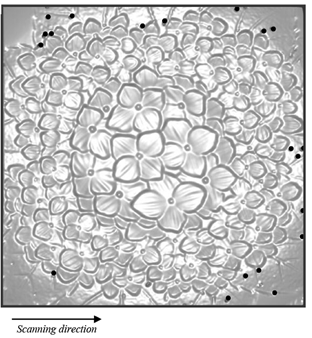 | Figure 16. CG graph of the glass dish surface produced from the measurement data of the new device |
On the other hand, a measurement using the diffusion reflection model of the laser detector was also performed for the glass dish surface. However, many failed points were observed in the leaf design area and completely transparent glass area. Especially, it was verified that the diffusion reflection model measurement with the laser detector is unsuitable for a completely transparent surface. It should be mentioned that the regular reflection model is associated with a stricter limitation to the inclination of a surface to be measured than the diffusion reflection model in general. For example, the laser detector used can inspect a surface only with a normal angle less than 20° with respect to the laser beam with the regular reflection model.From the above experiment results, it can be confirmed that the acceptation of the new laser detector makes the inspection for a transparent or semi-transparent surface possible although further improvement on the measuring performance is needed yet from the practical use point of view. Thus, developing a non-contact sensor with less limitation[28] to directly detect the contour profile should be an important issue in the future.
4. Conclusions
The major conclusions of the present research can be drawn as:(1) By developing a new sensing method for the reference position along a scanning line to separate the reference position detection from the contour profile measurement, both measuring accuracy and operation efficiency are significantly improved for whole device.(2) The employment of the AC servo motor controlled by a speed rule not only improves the capability of autonomous movement following the contour profile to be measured but also contributes to the inspection efficiency of the device.(3) The new laser displacement detector widens the applicable range for both the shape and material of a surface to be measured with the new device. Moreover, it is also verified that the measuring precision of the device is mainly affected by the characteristics of the laser detector, and the precision is in the order of 20 ~ 30 μm when the diffusion reflection model is applied.(4) The performance achieved with the new device is satisfactory for most measurement of clay models, and art and craft products since the offset operation is not required to create the geometric model of measured surface from the measured point data.
References
| [1] | Várady T, Martin RR and Cox J (1997) Reverse engineering of geometric models – an introduction, Computer-Aided Design, 29(4):255-268 |
| [2] | Li Y and Gu P (2004) Free-form surface inspection techniques state of the art review, Computer-Aided Design, 36(13):1395-1417 |
| [3] | Savio E, Chiffre LD and Schmitt R (2007) Metrology of freeform shaped parts, Annals of the CIRP, 56(2):810-835 |
| [4] | Mears L, Roth JT, Djurdjanovic D, Yang X and Kurfess T (2009) Quality and inspection of machining operations: CMM integration to the machine tool, Transactions of the ASME, Journal of Manufacturing Science and Engineering, 131(5):051006 |
| [5] | Kim KI and Kim K (1996) A new measuring strategy for sculptured surfaces using offset surfaces, Transactions of the ASME, Journal of Manufacturing Science, 118(4):646-651 |
| [6] | Song CK and Kim SW (1997) Reverse engineering: autonomous digitization of free-formed surfaces on a CNC coordinate measuring machine, International Journal of Machine Tools & Manufacture, 37(7):1041-1051 |
| [7] | Zhu L, Xiong Z, Ding H and Xiong Y (2004) A distance function based approach for localization and profile error evaluation of complex surface, Transactions of the ASME, Journal of Manufacturing Science and Engineering, 126(3):542-554 |
| [8] | Zhu L, Luo H and Ding H (2009) Optimal design of measurement point layout for workpiece localization, Transactions of the ASME, Journal of Manufacturing Science and Engineering, 131(1);011006 |
| [9] | Zhang X, Jiang X and Scott PJ (2011) Minimum zone evaluation of the form errors of quadric surfaces, Precision Engineering, 35(2):383-389 |
| [10] | Bernard A and Véron M (1999) Analysis and validation of 3D laser sensor scanning process, Annals of the CIRP, 48 (1):111-114 |
| [11] | Xi F and Shu C (1999) CAD-based path planning for 3-D line laser scanning, Computer-Aided Design, 31(7):473-479 |
| [12] | Feng H-Y, Liu Y and Xi F (2001) Analysis of digitizing errors of a laser scanning system, Precision Engineering, 25(3):185-191 |
| [13] | Son S, Park H and Lee K (2002) H. Automated laser scanning system for reverse engineering and inspection, International Journal of Machine Tools & Manufacture, 42(8):889-897 |
| [14] | Gao J, Gindy N and Chen X (2006) An automated GD&T inspection system based on non-contact 3D digitization, International Journal of Production Research, 44(1):117-134 |
| [15] | Zhang W, Peng Y, He F and Xiong D (2008) Drill flank measurement and flank/flute intersection determination, International Journal of Machine Tools & Manufacture, 48(6):666-676 |
| [16] | http://panasonic.co.jp/pfsc/products/ |
| [17] | http://www.mitakakohki.co.jp |
| [18] | Henselmans R, Cacace LA, Kramer GFY, Rosielle PCJN and Steinbuch M (2011) The NANOMEFOS non-contact measurement machine for freeform optics, Precision Engineering, 35(4):607-624 |
| [19] | Kakino Y, Iwata Y, Iwasaki Y and Otsubo H (1992) Study on a deviation detection type on-the-machine measurement of machined profile, Journal of the Japan Society for Precision Engineering, 58(6):1059-1064 (in Japanese) |
| [20] | Qiu H, Hashitani M, Nakano H, Inui S and Bosaka J (1999) A basic analysis of inspecting cylindrical gear accuracy on machine tool with a touch-trigger probe, Transactions of the Japan Society of Mechanical Engineers, 65C(631):1148-1155 (in Japanese) |
| [21] | Nakagawa H, Hirogaki T, Kaji Y, Kita Y and Kakino Y (2003) In-situ suitable controlled scan of laser stylus for point measuring of free surface, Journal of the Japan Society for Precision Engineering, 69(10):1423-1427 (in Japanese) |
| [22] | Koike Y, Kono D, Matsubara A and Yamaji I (2010) In-situ measurement by using a measurement-fused machining system, Journal of the Japan Society for Precision Engineering, 76(8):945-949 (in Japanese) |
| [23] | Miyoshi T, Kondo T, Saito K, Kamiya Y and Okada H (1990) Development of non-contact 3-D digitizing system, Journal of the Japan Society for Precision Engineering, 56(6):1021-1026 (in Japanese) |
| [24] | Miyoshi T, Takaya Y, Takizawa N and Fukuzawa R (1995) Development of non-contact profile sensor for 3-D free-form surfaces (3rd report) - optical ring image 3-D profile sensor, Journal of the Japan Society for Precision Engineering, 61(2):258-262 (in Japanese) |
| [25] | Chang M and Lin PP (1999) On-line free form surface measurement via a fuzzy-logic controlled scanning probe, International Journal of Machine Tools & Manufacture, 39(4):537-552 |
| [26] | Qiu H, Nisitani H, Kubo A and Yue Y (2004) Autonomous form measurement on machining centers for free-form surfaces, International Journal of Machine Tools & Manufacture, 44(9):961-969 |
| [27] | http://www.blender.org/ |
| [28] | Lee S-J and Chang D-Y (2007) A laser sensor with multiple detectors for freeform surface digitization, The International Journal of Advanced Manufacturing Technology, 31(11/12):1181-1190 |
 Abstract
 Reference
 Full-Text PDF
 Full-Text HTML