Vahid Monfared
Department of Mechanical Engineering, Zanjan Branch, Islamic Azad University, Zanjan, Iran
Correspondence to: Vahid Monfared , Department of Mechanical Engineering, Zanjan Branch, Islamic Azad University, Zanjan, Iran.
| Email: |  |
Copyright © 2012 Scientific & Academic Publishing. All Rights Reserved.
Abstract
Analysis of contact stress in rail and wheel is very prominent in mechanical and railway engineering. In this research, numerical analysis (FEA) of contact stress for two rolling bodies is studied by finite element method (FEM). The model considers the wheel and the rail as elastic deformable bodies and requires numerical solutions. The analysis of stresses is carried out by FEM. Next, critical area in rail and wheel are determined by results of stress analysis with numerical method. So we almost can rely on this numerical method and their results for prediction of critical points. To analyse the pressure of collection of the wheel and rail, elliptical, rectangular and circular contact surfaces are assumed for this study. With these assumptions, suitable results will be achieved. The rail fracture, failure and analysis of stress should be studied to prevent rail fracture and events. The analysis of contact stress is performed by FEM and it is compared with different contact surfaces results. These contact areas can be elliptical, rectangular or circular. Also, these results can be useful for analysing of crack creation in critical points and surfaces. Finally, good agreements are found between finite element method (FEM) and previous analytical results for determination of contact stress in rolling bodies.
Keywords:
Contact Stress, FEA, Rolling Bodies, Elliptical, Rectangular and Circular Surfaces
1. Introduction
The finite element method (FEM) is computationally intensive, owing to the required operations on very large matrices. In the early years, applications were performed using mainframe computers, which, at the time, were considered to be very powerful, high-speed tools for use in engineering analysis. Mechanics of the rail and wheel collection contact is one of the elemental and basic are as of the study in mechanical and railway engineering, requiring both very important and large application skill and reliable analysis approaches. Analytical formulations depicting the physics of this fact are defined only for special type of simple contact geometries, so for more intricate and complex geometries the analytical models employing closed forms remain hard to comprehend. Railway engineers and researchers successfully are applied one of the numerical computation methods known as Finite Element Analysis (FEA) or simple direct formulations into rail–wheel contact problems to verify their results by comparing them to their actual life information determined over the past years. Determination of the contact areas requires knowledge of some geometric constants used in the formulation in the rolling bodies. Two solid discs and rolling body are put together to generate an elliptic contact surface factors. The wheel-rail contact can be described by the general case of an elliptic contact surface. Although there are some important simplifications that can be applied in modelling other formats of the contact surfaces, these will not be developed here. Evaluating surface and subsurface stresses requires the determination of the displacements field. One also needs to calculate the contact surface. Wheel and rail contact and the damage to both surfaces continue to preoccupy railway engineers. Understanding the loading into the track and the stresses they generate is the first step in identifying the root cause of the problem.Contact stresses are significant when contact is not fixed but cyclic in nature such as locomotive wheel-rail road rail. In order to study the stress analysis, factors of critical stress must be determined. One of the frequent flaws and defects of rails which lead to their failure and fracture is a vertical crack on the end of the rails. This is principally because of loading will make a tensile and compressive stress on the end of the rail. Therefore, these stresses with the tensile and compressive stresses will cause compressive and tensile stresses on the end of rail respectively and these tensions and compressions lead to growth of vertical crack at the end of the rail, and eventually cause failure and fracture in it. The important and main objective of this research is to find the critical (dangerous) contact stresses and surface in any place of wheels and rails near the contact region by FEM. Smith and Liu[1] studied stresses due to tangential and normal loads on an elastic solid with application to some contact stress problems. Haines and Ollerton investigated contact stress distribution on elliptical contact surfaces subjected to radial and tangential forces[2]. Some useful results in the classical Hertz contact problem were presented by Sackfield and Hills[3]. Analysis of wheel–rail interaction using FE software has been studied by Sladkowski and Sitarz[4]. Wiest et al.[5] investigated assessment of methods for calculating contact pressure in wheel-rail/switch contact. Donzella and Petrogalli proposed failure assessment diagram for components subjected to rolling contact loading[6]. Monfared[7] proposed new analytical formulation for contact stress and prediction of crack propagation path in rolling bodies and comparing with finite element model (FEM) results statically. Prediction of Mechanical Behaviour of PZT and SMA has been studied by Monfared and Khalili[8].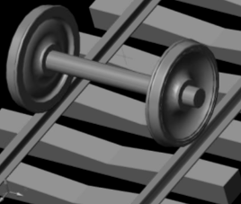 | Figure 1. Position of contact of wheel and rail |
2. Material and Methods
In this paper, analysis of contact stress for two rolling bodies has been presented by finite element method (FEM). First we should determine the critical surface of stress. We can determine the positions of critical tension by FEM (Figure 1). Of course there may be some difference in the value of these stresses that we discuss in the section of stress analysis theory. For fast fracture, the size of the crack must be about 2.4 inches, so the area of the crack will be larger than the end surface of the rail. Vertical cracks will grow faster than other cracks. According to analytical and numerical results, the direction of the crack growth and also the prediction of the fracture depend on the values of maximum stress and displacement or the value of multiplying of maximum stress and displacement. That is, we can determine the maximum stress, displacement and critical surface and stress by finite element method (FEM). In order to analyse the contact stresses, numerical methods are used. The induced loads in the contact area have been done by FEM analysis. Figures 5, 6 show that the standard UIC60 and position of forces in the contact surface. The induced load to one wheel is about 10 tones. As well as Contact surfaces are elliptical, rectangular and circular areas in this work approximately. In this research the axial load is considered about 22 tones. The area of contact surface is assumed about  . The loadings that are induced to the rail and the wheel are 50 to 200 KN. For modelling of the wheel and the rail, we use the rail profile UIC60 and two axial wheel of bogie H665. According to above information the pressure equal to
  is induced at the position of contact of wheel and axel, Figure 3.
3. Results and Discussion
In this section, results of the numerical analysis by finite element method (FEM) in rail-wheel collection under static loading are presented. Then some results of FEA modelling is given by Table 1. First, position of contact of wheel and rail has been shown in Figure 1.Finite element model (FEM) of rail and wheel shown in Figures 2, 3 and 4. This 3D model geometry is transferred to the ANSYS software and meshed with SHELL63, SOLID45, 8noded, hex elements as shown in Figure 2. Contact between Rail and Wheel is modelled using ANSYS Contact 173 elements placed on wheel and rail. Finite element model mesh (Wheel and Rail) is obtained having a total of 35740 elements and 22830 nodes. In this research, 10 ton per wheel is applied approximately. Wheels are assumed to operate on a flat and straight path, so lateral loads to the system are neglected. Rotational effects of the wheel are also ignored.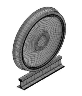 | Figure 2. Finite element modeling wheel and rail |
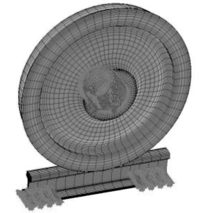 | Figure 3. Finite element modeling wheel and rail with static loads |
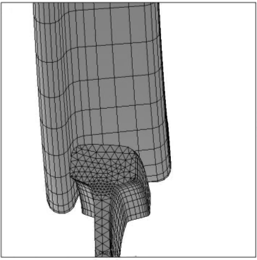 | Figure 4. Finite element modeling wheel and rail contact |
Geometry and position of contact for UIC60 were presented in Figures 5, 6.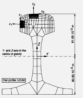 | Figure 5. Position of contact for UIC60 |
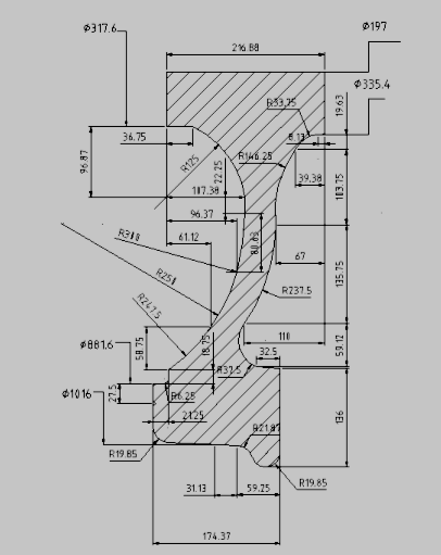 | Figure 6. Geometry of contact for UIC60 |
Now, stress and deflection analysis are done by finite element method (FEM) statically. Deflection and displacement of rail has been presented in Figure 7.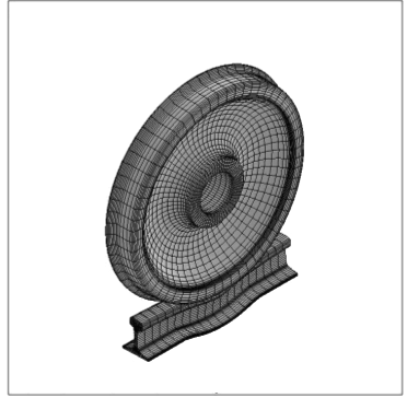 | Figure 7. Deflection and displacement of rail |
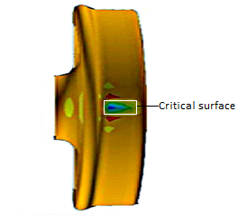
Von Mises stresses distribution in contact of wheel and rail with finite element modelling has been shown in Figure 8. Also in Figure 8 critical surfaces and stresses were shown. That is, rail can be ruptured in critical points or areas under static loadings possibly. On the other hand, it is possible micro crack was established in this points or surfaces.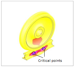 | Figure 8. Von Mises stress in contact of wheel and rail with FEM |
 | Figure 9. Equivalent stress in rail by FEM |
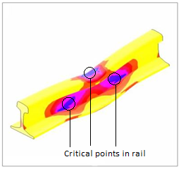
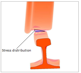
Also, equivalent stress in rail has been analysed by finite element analysis (FEA) statistically shown as Figure 9. In addition, critical points and surface has been specified in this Figure. Three critical and dangerous points and surfaces have been characterized in Figure 9, which may be fail and yield in mentioned points.Stress distribution and critical points and surface in rail and wheel-rail have been shown in Figures 10, 11 respectively.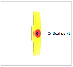 | Figure 10. Stress distribution in rail |
 | Figure 11. Stress distribution in rail and wheel |
Stress distribution individually has been investigated by finite element analysis (FEA) in Figure 12, 13. In addition, critical surfaces have been shown and marked in these Figures.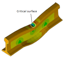 | Figure 12. Stress distribution in rail |
 | Figure 13. Stress distribution in wheel |
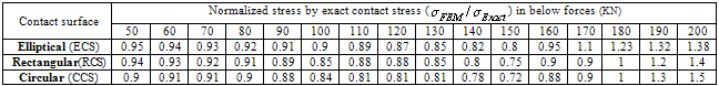
Now, the final results are shown for determination of critical points in rail and wheel statistically in Figure 14. This figure shows that there are two critical and dangerous surfaces in collection of rail and wheel. Also, stress results have been determined by finite element method (FEM) in three different types in Table 1. That is, elliptical, rectangular and circular contact surfaces (ECS, RCS, CCS) have been assumed for numerical stress analysis. These results show that stresses are similar to the exact analytical results by assumption of elliptical contact surface.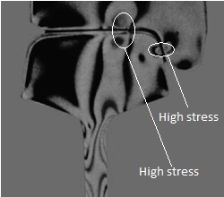 | Figure 14. Two critical and dangerous points in collection of rail and wheel in contact state statically |
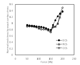 | Figure 15. Results of contact stress by finite element method (FEM) with three assumptions (elliptical (ECS), rectangular (RCS) and circular (CCS) contact surface) |
Table 1. Results of contact stress by FEM with three assumptions (Elliptical, Rectangular and Circular contact surface)
 |
| |
|
In addition, these results shown that stresses are approximately equal in small loadings unlike a high loadings.Results of contact stress by FEM with three assumptions (elliptical (ECS), rectangular (RCS) and circular (CCS) contact surface) have been shown in Figure 15. In Table 1,  (analytical exact formulation) has been determined by formulation obtained by reference[7].
4. Conclusions
Finite element method (FEM) is widely used analysis-and-design technique. To analyse the pressure of collection of the wheel and rail elliptical, rectangular and circular contact surfaces (ECS, RCS and CCS) were assumed. With these assumptions, acceptable results attained. In present paper, contact stress analysis of two rolling bodies (Rail-Wheel) was presented by finite element method (FEM). Also, critical surface and important points in collection of rail-wheel were specified by FEA.Results shown that were two critical and dangerous surfaces in collection of rail and wheel statistically. Elliptical, rectangular and circular contact surfaces (ECS, RCS, CCS) were assumed for numerical stress analysis.These results show that stresses were similar to the exact analytical results by assumption of elliptical contact surface. As well as, results of contact stress with assumption of rectangular contact surface were more accurate than the contact stress results by assumption of circular contact surface. In addition, these results shown that stresses are approximately equal in small loadings unlike a high loads.These critical surfaces may be cause creation of micro and macro cracks. Eventually, good agreement was found between finite element method (FEM) and previous analytical results for determination of contact stress in rolling bodies.
References
| [1] | Smith, J.O., Liu, C.K., 1953, Stresses due to tangential and normal loads on an elastic solid with application to some contact stress problems, J. Appl. Mech., 20, 157-166. |
| [2] | Haines, D.J., Ollerton, E.,1963, Contact stress distribution on elliptical contact surfaces subjected to radial and tangential forces, Proc. of Inst. of Mechanical Engineers, London 177 (4), 45-54. |
| [3] | Sackfield, A., Hills, D.A., 1983, Some useful results in the classical Hertz contact problem, Journal of Strain Analysis, London 18 (2), 101-105. |
| [4] | Sladkowski, A., Sitarz, M., 2005, Analysis of wheel–rail interaction using FE software, Wear. 258, 1217–1223. |
| [5] | Wiest, M., Kassa, E., Daves, W., Nielsen, J.C.O., Ossberger, H., 2008, Assessment of methods for calculating contact pressure in wheel-rail/switch contact, Wear., 265, 1439–1445. |
| [6] | Donzella, G., Petrogalli, C., 2010, A failure Assessment Diagram for Components Subjected to Rolling Contact Loading, Int. J. Fatigue., 32(2), 256-268. |
| [7] | Monfared, V., 2011, A new analytical formulation for contact stress and prediction of crack propagation path in rolling bodies and comparing with finite element model (FEM) results statically, Int. J. Phys. Sci., 6(15), 3613-3618. |
| [8] | Monfared, V., Khalili, M.R., 2011, Investigation of Relations between Atomic Number and Composition Weight Ratio in PZT and SMA and Prediction of Mechanical Behavior, Acta phys. Pol. A., 120, 424-428. |
 Abstract
 Reference
 Full-Text PDF
 Full-Text HTML