Gun-Hee Kim , Jeong-Won Lee , Young-Moo Heo , Gil-Sang Yoon
Molding & Forming Technology R&D Group, Korea Institute of Industrial Technology, Incheon, 406-840, Korea
Correspondence to: Gil-Sang Yoon , Molding & Forming Technology R&D Group, Korea Institute of Industrial Technology, Incheon, 406-840, Korea.
| Email: |  |
Copyright © 2012 Scientific & Academic Publishing. All Rights Reserved.
Abstract
The polymeric biochip has been focused as a cheap, rapid and simplified method to replace the existing biochemical laboratory works. This biochip is formed miniaturized lab functionalities on a chip with the development of MEMS technology. This has many micro-fluidic channels for the flow of sample and reagents, mixing and detection task. Existing technologies for the biochip fabrication are utilizing various micro pattern forming methods, such as etching, LIGA, and micro-imprinting etc. In this study, an injection molding process with micro mold was applied to the mass production of polymeric biochip which contains micro-fluidic channel. Micro cutting process was applied to fabricate the core feature for molding micro-fluidic channel. Therefore, a series of micro cutting experiments using micro endmill were performed to determine optimum cutting conditions. Besides, the low temperature micro-cutting experiments using micro endmills were performed to improve the quality of micro mold core by reducing the burr and surface roughness. After the verification of low temperature micro-cutting process efficiency, this process was used to fabricate required mold core for micro feature. Finally, test injection molding process using manufactured micro mold and COC polymer were performed, and then the results were investigated.
Keywords:
Polymeric biochip, Injection molding process, Micro-cutting process
Cite this paper:
Gun-Hee Kim , Jeong-Won Lee , Young-Moo Heo , Gil-Sang Yoon , "Fabrication of Polymeric Biochips With µ-Fluidic Channel by Injection Molding Technology", Journal of Mechanical Engineering and Automation, Vol. 2 No. 1, 2012, pp. 17-22. doi: 10.5923/j.jmea.20120201.04.
1. Introduction
In recent, with the development of micro fabrication technologies, biotechnical analytical processes can be rapidly performed using miniaturized biochip. Generally, biochip can be categorized into two groups; micro-array and micro-fluidic chips. The micro-array has an array of miniaturized test site on a chip. The number of micro-arrays varies from a hundred to a few thousand. Because the micro-fluidic chip can perform multiple tasks in a biochemical analysis laboratory, such as mixing, reaction, separation, and detection etc., it is called as LOC (lab-on-a-chip).[1,2] The micro-fluidic chips have various advantages such as short analysis time, small specimen and reagent, low cost, high accuracy, and easy usage etc. Therefore, the micro-fluidic chips have been interested as high-valued technology in related industries.[3-6] Unlike the micro-array chips, the micro-fluidic chips have many micro-channels to connect the unit tasks for consecutive processing steps.[1] The continuous flow of input test samples and reagents through the micro-channels can make the analytical process to be performed on a chip by minimizing sample contamination and processing time. Existing substrate materials for micro-fluidic chips fabrication are glasses or polymers. The substrate for micro-fluidic chips should be biocompatible since most of they are used for biological analysis. Besides, various material properties such as mechanical strength, porosity, and hydrophobicity, etc., are required for real application. Fabrication procedures of micro-fluidic chips depend on the used material and complexity of the chip. Existing fabrication method of micro-fluidic chips is based on the soft lithography, such as wet-etching, micro-contact printing, and hot-embossing, etc.[2-5] Also LIGA and micro-powder blasting processes are applied to form required micro-channels on the biochips.[7] Several studies were performed to replicate micro-fluidic chips using metal mold masters which were prepared by CNC micro-milling processes.[8-11] In these study, brass[7] and aluminium masters[9-11] with micro-fluidic channels were fabricated to replicate PMMA and thermosetting resin by hot embossing.In this paper, to establish the basis of the micro pattern fabrication and mass production of polymeric biochip using injection molding process, micro cutting method was applied to form micro-channels on the micro injection mold core. As a first step, simplified micro-channels were designed based on existing research results. Then, micro cutting experiments using micro endmill were performed to determine optimum machining conditions to improve better surface roughness and shape accuracy. Besides, the low-temperature micro cutting experiments were executed for reducing burrs. Finally, the test injection processes using fabricated micro injection mold and COC resin were performed, and the results were analysed. As the results, it can be observed that the required micro-fluidic chips can be obtained using injection molding process.
2. Design of Micro-Fluidic Channel for Biochip
Figure 1 shows a simplified micro-fluidic fields design. The designed biochip is composed of an upper plate C and a bottom plate D. By closing the upper plate, square-type micro channels which has 100㎛ width and 100㎛ depth can be formed between the plates. As shown in the Figure 1, A1 and A2 are the inlet ports for the reagent and test samples; B is the sensing port of the reaction results. The micro-fluidic channel is formed between the ports A and B for sufficient mixing of the reagent and test sample. It is designed to have 90mm of total flow distance and 70mm of detection length.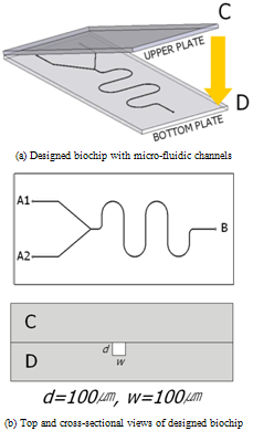 | Figure 1. Designed biochip for test injection molding |
3. Micro Cutting Experiments
3.1. Micro Cutting System
The micro cutting system used in the micro cutting experiments in this study is as shown in Figure 2. The structure of system is similar to the conventional 3-axis machine tool with the spindle mounted to the vertical axis. For the micro endmilling process, the main axis of micro cutting system was applied with an air bearing type high frequency spindle that can be accelerated up to 100,000rpm in order to reduce the amount of feed per tooth considering the characteristics of micro cutting process which has relatively large amount compared to the macro cutting process. In addition, since vibration delivered from external sources should be very importantly considered with the self-exited vibration, four isolators were installed under a surface plate on which micro cutting system. The cutting lubrication oil can be sprayed in the form of mist considering very small size of cutting area during the micro cutting process. Table 1 is a list of the detailed specifications of the micro cutting system.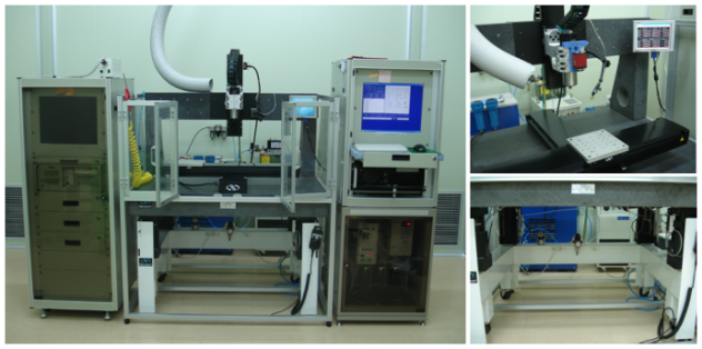 | Figure 2. Micro cutting system used in this study |
| Table 1. Specifications of the micro cutting system |
| | Traveling range | X,Y-axes (600mm), Z-axis (200mm) | | Resolution | All axes 0.1㎛ | | Accuracy | X,Y-axes (6㎛), Z-axis (2㎛) at full traveling range | | Repeatability | All axes 0.2㎛ at full traveling range | | Rotational speed | Max. 100,000rpm | | Spindle runout | Max. 0.7㎛ | | Specimen load | Max. 10kg |
|
|
3.2. Experiments for Micro Burr Reduction
The burr size created during the micro cutting as contrasted with micro cutting feature size are much larger than that of macro cutting process. This burr causes more serious problems to post-cutting processes and the quality of micro cutting feature. In addition, it is very difficult to efficiently implement deburring processes for burrs created during micro cutting process due to very small micro feature size. Therefore, the minimization of burr created during micro cutting process is the most desirable for post processes to be implemented after cutting process.In this study, the low temperature micro cutting process for minimizing the tool wear and cutting heat rapid-cooling as the main factors which generate burr was proposed and verified. The low temperature micro cutting process is implemented while spraying low temperature pressured air at a level -20~-50℃ to the very small micro cutting area. Table 2 show the efficiency verification experiments conditions of proposed lubricant method. Figure 3 shows the configuration of devices for the micro cutting experiments under various cutting lubrication conditions.| Table 2. Detailed experimental conditions |
| | Cutting tool | Dia. 300㎛ 2-flute endmill | | Workpiece | NAK80 (20mm×20mm×15mm) | | Cutting velocity | 30m/min (31,847rpm) | | Feed per tooth | 0.86㎛/tooth (55mm/min) | | Depth of cut | 100㎛ (10㎛/step×10step) | | Total cutting length | 2,100mm | | Cutting lubricant | No lubricant cuttingWet cutting with cutting oil (Room temperature wet cutting)Wet cutting with cutting oil and low temperature compressed air(-20℃, 2bar) |
|
|
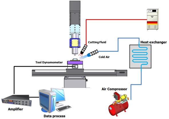 | Figure 2. Diagram of experimental setup |
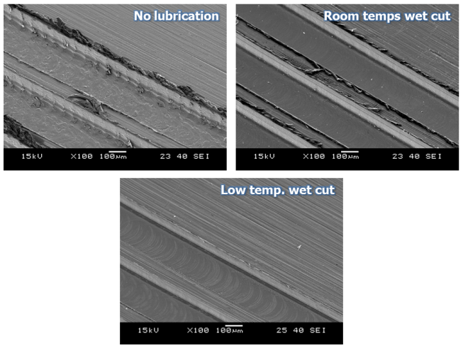
In the experiment of the ‘no lubrication cutting condition’, the largest changes in cutting force occurred and it could be identified that cutting force changed quite irregularly from the time point of surpassing a cutting length of 300mm. (Figure 3) It is considered that this phenomenon was caused because the volume and strength of the tool edge were changed due to growth and dropouts of the built-up-edges of the tool, flank wear and tool edge wear. In the experiment under wet cutting conditions including ‘Room and low temperature wet cutting conditions’, it could be identified that generally much smaller cutting force occurred compared to the ‘no lubrication condition’ mentioned earlier and the amounts of variation in cutting force occurred in relation to cutting length were also relatively small. (Figure 3) However, it could be seen that whereas cutting force increased slightly under ‘Room temperature wet cutting condition’, it did not increase under ‘Low temperature wet cutting condition’ even when processing lengths increased. Since low temperature compressed air was delivered to minute cutting area together with cutting oil, chip removal and cutting heat cooling were done very quickly and the micro cutting area was maintained with relatively low temperature compared to other conditions. By this environment of micro cutting area, friction heat on tool flanks was also cooled. From the tool images in Figure 4 too, it can be identified that the states of tool edge area and flank surface were relatively better compared to ‘Room temperature wet cutting condition’.Tool wear and cutting force are closely related with each other and theses phenomena are directly connected to the quality of micro cutting features. Therefore, the results of analysis of cutting force and tool wear relative to cutting lubrication conditions can be identified in the micro cutting features SEM images in Figure 5. In experimental condition of ‘no lubrication’, as in the SEM images, the normal micro cutting process was not caused becausecutting heat generated excessively in minute cutting areas with tool wear were progressed very fast. Finally, it could be identified that the experiment case applied with ‘Low temperature wet cutting condition’ has the best quality of micro cutting features in the aspect of burr occurrence.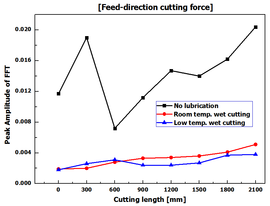 | Figure 3. Micro cutting force of feed-direction with cutting length |
 | Figure 4. Tool images at 2,100mm cutting length according to cutting lubrication conditions |
 | Figure 5. Cutting methods for experiments |
3.3. Experiments for Surface Roughness and Shape Accuracy Improvement
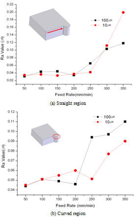
Surface roughness in the fabricated micro-fluidic channel is an important factor to determine the liquid fluidity. It is very important to decide optimum machining conditions based on the required experimental results because the macro-field finishing processes, such as polishing and lapping are almost impossible for micro-fluidic channel fabrication. Thus, the relationship between the micro cutting conditions and surface roughness was investigated through a series of experiments. A test specimen was designed to have both regions with same curvature as shown in Figure6because the designed micro-fluidic channels in this study have straight and curved features. The specimen was cut by two methods at constant spindle speed of 17,000rpm and by changing the feedrates as follows; (a) 1 pass cutting, depth-of-cut was 100㎛, (b) 10 times of step cutting, depth-of-cut for each step was 10㎛. Inspection results of surface roughness are shown in Figure. 7 for straight and curved region, respectively. The best results were observed when the depth-of-cut was 100㎛ and feedrate was 50mm/min for both of the straight (Ra=31nm) and curved (Ra=44nm) regions.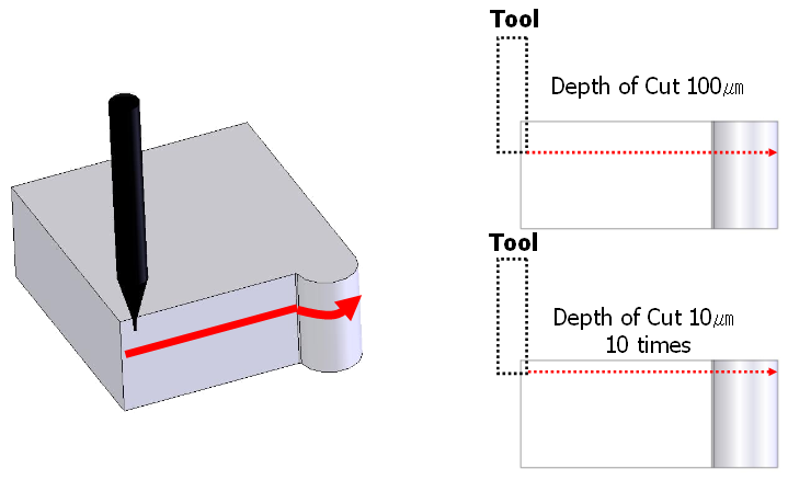 | Figure 6. Cutting methods for experiments |
 | Figure 7. Measured surface roughness |
As a next step, the influence of micro tool diameter variation was investigated for the improvement of shape accuracy. For the experiments, micro tools of 200 and 400㎛ diameter were used and the results were analysed. Depth-of-cut was 100㎛ and federate was 50mm/min according to the previous experimental results. Measured results of the machined micro channels and 3D profile are shown in Figure 8 (tool diameter=200㎛) and 9 (tool diameter=400㎛). From the figures, it can be seen that the micro endmill of 400㎛ diameter gives better shape accuracy at same machining conditions.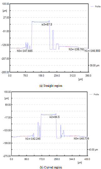 | Figure 8. Measured profiles of micro channels machined using 200㎛ micro endmill |
4. Fabrication of Mold and Test Injection Experiments
In this study, a test injection mold for biochip was designed as shown in Figure 10. It has simple moldbase structure for easy alignment and fabrication. The mold has 4 cavities, which is surrounded by isolation plates to prevent heat loss, and to maintain the inside temperature constant during injection process. Using the mold, the upper and bottom plates of the biochips can be manufactured at a time by one process.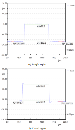 | Figure 9. Measured profiles of micro channels machined using 400㎛ micro endmill |
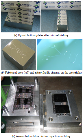
Based on the previous experimental results, the optimum conditions for fabricating micro channels on the injection mold core were determined as shown in Table 3. SKD11 was used for manufacturing ejecting pin and guide bush; and NAK80 was used for cavity and core for micro channel molding. Figure 11 shows the mirror-finished plates for micro-channel machining fabricated core and assembled mold set for the test injection experiments. As shown in figure, 4 cavities are assembled in a mold set.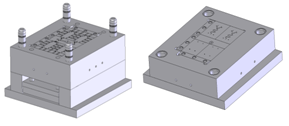 | Figure 10. Designed injection mold set |
 | Figure 11. Fabricated core and test injection mold |
| Table 3. Applied micro cutting conditions for core fabrication |
| | Cutting tool | Dia. 400㎛ 2-flute endmill | | Core material | NAK80 | | Tool rotational velocity | 17,000 rpm | | Feed per tooth | 50mm/min | | Depth of cut | 100㎛ (10㎛/step×10step) | | Side depth of cut | 10㎛ | | Cutting lubricant | Wet cutting with cutting oil and low temperature compressed air(-20℃, 2bar) |
|
|
| Table 4. Thermal properties of COC |
| | COC | 8007S-04 | | Melt temperature | 230℃ | | Glass transition temperature | 80℃ | | Viscosity index (MPI data) | VI(260)0091 |
|
|
The polymer used in the test injection process were COC (cyclic olefin copolymer), which have good material properties, such as high transparency, low double refraction, low absorptive property, and biocompatibility, etc. Applied COC resin is ‘Topas 8007S-04’. Thermal properties and viscosity characteristicsof COC are shown in Table 4. Test injection process using the fabricated mold set is shown in Figure 12(a), and the injected samples of biochip are shown Figure 12(b). From the figures, it can be seen that the micro-channels are formed on the polymer plates successfully.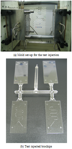 | Figure 12. Test injection process and samples of polymeric LOC |
5. Conclusions
In this study, injection mold core for micro-channel molding on the biochip were fabricated using micro endmilling process. Micro rib filling experiments were performed to evaluate the characteristics of polymers. Besides, the test injection process was performed using the fabricated inserts and mold set. From the results of this study, it can be shown that the method can be applied for the mass production of biochips. The results of this study can be summarized as follows:(1). For reduction of micro burr, the low temperature cutting process was proposed and the burr reduction efficiency of cutting process was verified by the micro cutting experiments.(2). In micro end-milling process, the best surface roughness could be obtained at depth-of-cut was 100㎛ and federate was 50mm/min. Under the condition, surface roughness of Ra=31nm was obtained for the straight regions, and Ra=44nm for curved regions.(3). When tool diameter was 400㎛, better shape accuracy of the micro-channel could be obtained than the 200㎛ diameter tool.(4). Test injection process was performed successfully. Thus, it can be shown that the applied method can be a way for the mass production of biochips.
ACKNOWLEDGEMENTS
This study has been financially supported by the development of industrial technology project of Korea Institute of Industrial Technology (KITECH)
References
| [1] | Song, S. and Lee, K.Y., “Ploymers for Microfluidic Chips,” Macromolecular Research, Vol. 14, pp.121–128, Apr. 2006. |
| [2] | D. R. Reyes, D. Iossifidis, P.-A. Auroux and A. Manz, “Micro Total Analysis Systems. 1. Introduction, Theory, and Technology,” Analytical Chemistry, vol. 74, pp. 2623–2636, May, 2002. |
| [3] | Ahn, C.H. “Application of Micro Molding Technology to BioMEMS Components and Systems,” University of Cincinnati, International technical report to KITECH, Korea. |
| [4] | Blattert C., “Separation of Blood Cells and Plasma in Microchannel Bend Structures,” in Proc. Micro-TAS2004, 2004, pp.483–485. |
| [5] | M. J. Heller, “DNA Microarray Technology: Devices, Systems, and Applications,” Biomedical Engineering, vol. 4, pp.129–153, Aug. 2002. |
| [6] | K.M. Kurian, C. J. Watson and A.H. Wyllie, “DNA chip technology,” The Journal of Pathology, vol. 187, pp. 267–271, Feb. 1999. |
| [7] | Jakeway, S. C., de Mello, A. J., Russell, E. L., “Miniaturized Total Analysis Systems for Biological Analysis,” Analytical Chemistry, vol. 366, pp. 525–539, Jan. 2000. |
| [8] | M.L. Hupert, W.J. Guy, S.D. Llopis, H. Shadpour, S. Rani, D. E. Nikitopoulos and S. A. Soper, “Evaluation of micromilled metal mold masters for the replication of microchip electrophoresis devices,” Microfluid Nanofluid, vol. 3, pp. 1–11, June 2006. |
| [9] | Mecomer, J.S., Stalcup, A.M., Hurd, D. Halsall, H.B., Heineman, W.R., Seliskar, C.J., Wehmeyer, K.R., Limbach, P.A., “Analytical Performance of Polymer-Based Microfluidic Devices Fabricated by Computer Numerical Controlled Machining,” Analytical Chemistry, vol. 78, pp.936–941, Feb. 2006. |
| [10] | Mecomber, J.S., Hurd, D. and Limbach, P.A., “Enhanced machining of micron-scale features in microchip molding master by CNC milling,” International Journal of Machine Tools & Manufacture, vol. 45, pp.1542–1550, Feb. 2005. |
| [11] | D.S. Zhao, B. Roy, M.T. McCormick, W.G. Kuhr and S.A. Brazill, “Rapid fabrication of a poly(dimethylsiloxane) microfluidic capillary gel electrophoresis system utilizing high precision machining,”Lab on a Chip, vol. 3, pp. 93–99, Mar. 2003. |


 Abstract
 Reference
 Full-Text PDF
 Full-Text HTML