Zheng (Jeremy) Li
School of Engineering, University of Bridgeport, Bridgeport, CT 06604, USA
Correspondence to: Zheng (Jeremy) Li , School of Engineering, University of Bridgeport, Bridgeport, CT 06604, USA.
| Email: |  |
Copyright © 2012 Scientific & Academic Publishing. All Rights Reserved.
Abstract
Energy efficiency is one of the most important objectives in today’s engineering systems. This paper introduces a new type of energy-saving refrigerating system based on functional and performance studies, computer-aided 3-D modeling, computational fluid dynamic analysis, and the prototype testing. The main advantages of this energy-saving regenerative system include: higher performance efficiency due to less frictional force, simplified mechanical system, less vibration due to its symmetrical structure design, less frictional losses between free piston and cylinder, and cost-saving in mechanism due to low tolerance requirement manufacturing of the system components.
Keywords:
Energy Efficiency, Refrigeration Systems, Optimized Design, Computational Simulation
Cite this paper:
Zheng (Jeremy) Li , "Computer-Aided Modeling and Analysis of an Energy-Saving Refrigerating System", Journal of Mechanical Engineering and Automation, Vol. 2 No. 1, 2012, pp. 9-12. doi: 10.5923/j.jmea.20120201.02.
1. Introduction
The efficient and energy-saving refrigerating systems are being designed and developed in these years and more researches have been done to improve its performance and accelerate the implementation of energy efficiency[1,2]. With recent research and development in energy field, the impact of refrigerating energy consumption and its relationship with energy-saving system implement is one aspect of importance in industrial and engineering systems[3,4]. The concept of energy-saving engineering systems is directly connected with the rational utilization of energy, both at a local and global level [5]. It can be extended and applied to industrial, commercial and residential refrigeration systems [6]. There are many applications of refrigerating systems including gas liquefaction, compressed air purification, gasoline production in , tempering of steel and cutlery in metal work, and temperature controls in food transportation [7, 8]. Particular importance was given to the design and development of more efficient refrigerating equipments, implementation of heat recovery and thermal accumulation, and optimizing the thermal and mechanical efficiencies of refrigerating systems [9, 10].
2. Cyclic Analysis on New System
This paper introduces a new type of energy-saving regenerative refrigerating system based on 3-D modeling, computer-aided analysis, computational simulation, andprototype testing. The prototype and simplified energy- saving mechanism are depicted in Figs. 1 and 2. The functioning cycle of this system is indicated by P-V diagram in Fig. 3. The new mechanism design makes this refrigerating system more simplified. Compared with Solvay refrigerating system, the middle fluctuating cavity Vme (V’me) is more simple and compact due to less components in this refrigerating system. The manufacturing cost is low due to low tolerance requirement for most components in this new system. In addition, partial compressive work in the middle fluctuating chamber can be retrieved and converted to the useful motive work, compared with Solvay system that no energy can be retrieved from middle chamber in which the total compressive work has been exchanged to the heat being discharged to the air. Moreover, the working efficiency of this new system is improved since the refrigerating capacity can be output through two ends in cylinder. Also the vibration and shock are reduced because of its symmetrical structure design. The phase angle of various functional curves can be easily adjusted by selecting proper parameters in this system, such as width of inlet and outlet of free piston, and size of small hole in the middle fixed plate. Because there is no need to adjust the tension of elastic ring in order to change the phase angle of functional curves in this new machine, the frictional losses are significantly reduced.Referring Fig. 2, there are two compressive cylinders Vc (V’c) and two expansive cylinders Ve (V’e) that are symmetrically arranged in this new system. Also there are two free pistons F (F’), one fixed plate G with a small hole, and two middle fluctuation chamber Vme (V’me). Due to its symmetrical setup, we only analyze the functioning cycle on the right side, namely Vc, Ve and Vme, H and F. The initial condition of this refrigerating machine is indicated in Fig.2. To simplify the cyclic analysis, the steady working condition is assumed at its initial stage of the cycle: piston H is at the bottom position in the compressive cylinder and free piston F is at the right end in expansive cylinder. Because some gas with high pressure (P=Ph) enters Vmc through a small hole in final period of last working cycle, gas with low pressure (P=Pl) in Vmc is mixed with high pressure gas. The mixed pressure in Vmc is Pwa. When H begins to move upward in Vc, gas in Vmc is assumed not flowing into V’mc because the moving speed of the piston is fast and the diameter of hole is small. Since the left side pressure of F is higher than right side pressure of F (Pmc = Pwa >Pe), F does not move, Pe reaches to Ph, and Ve increases from zero to V2 as H continuously moves up. This process is shown by curve 1-2 in Fig.3. Then gas in Vmc flows into V’mc. In this period, pressure at the left and right sides of F is same and F moves to the left with no change of speed. When angle of crank α nears 180°, Ve increases from V2 to V3 and the process is indicated by line 2-3. In the earlier stage that H moves downwards in Vc, F does not move because gas in V’mc is assumed not entering Vmc. Pe reduces from P3 to P4 with its corresponding process of 3-4. As H continuously moves downwards in Vc, gas in V’mc flows into Vmc through small hole and F moves to the right end in the expansive cylinder with constant speed. This process is 4-1 and the full functioning cycle consists of all above processes.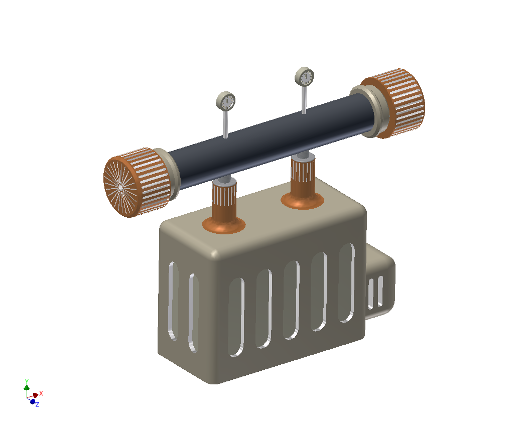 | Figure 1. New energy-saving refrigerating system |
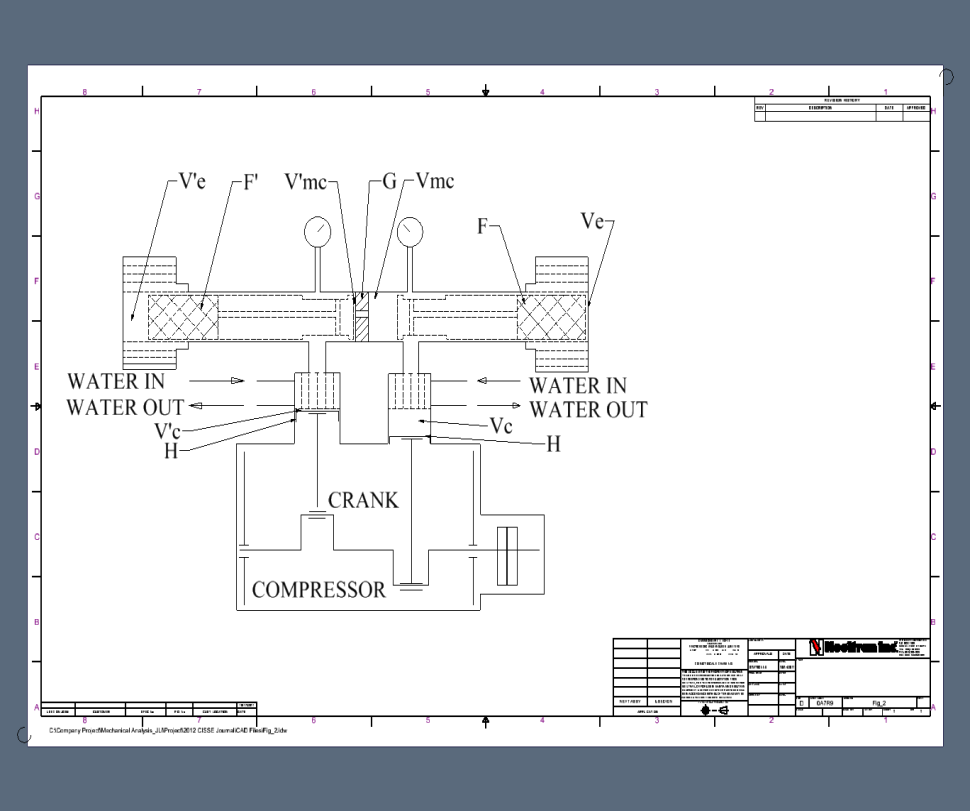 | Figure 2. Simplified sketch of refrigerating system |
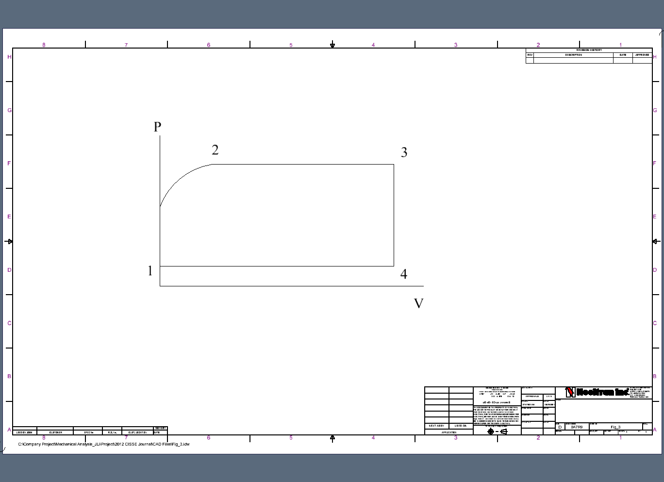 | Figure 3. P-V diagram of cycle in expansive cavity |
3. Computer-aided Modeling and Simulations
The computer-aided modeling and numerical simulations have been performed to verify the function of this new system. Through the computational simulation, all functional parameters can be found as follows:Because the compressive piston H moves in sine law,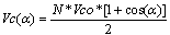 | (1) |
If Vk is the volume of clearance,  | (2) |
 | (3) |
When compressive piston H moves up with crank angle turning to β,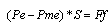 | (4) |
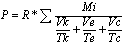
 | (5) |
Assume:Combine (3) and (5),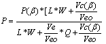 | (6) |
From equation (6), the solution of P = P (α) can be found after relation between Ve and α being determined. Based on the ’s second law, the differential equation of free piston movement can be derived as follows: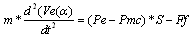 | (7) |
Combine equations (6) and (7):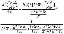 | (8) |
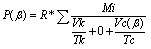
HereP(β) can be calculated by the following equation | (9) |
and Vc(β) can be found by equation (5).By computer-aided simulation, Vc(α ) and P(α) can be determined All the simulation results depicted in Figs 4, 5, 6, 7 and 8 show feasible and proper function of this energy-saving regenerative refrigerating system.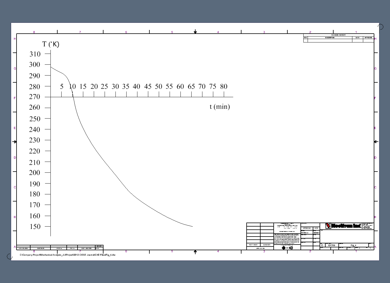 | Figure 4. Refrigerating temperature vs. time |
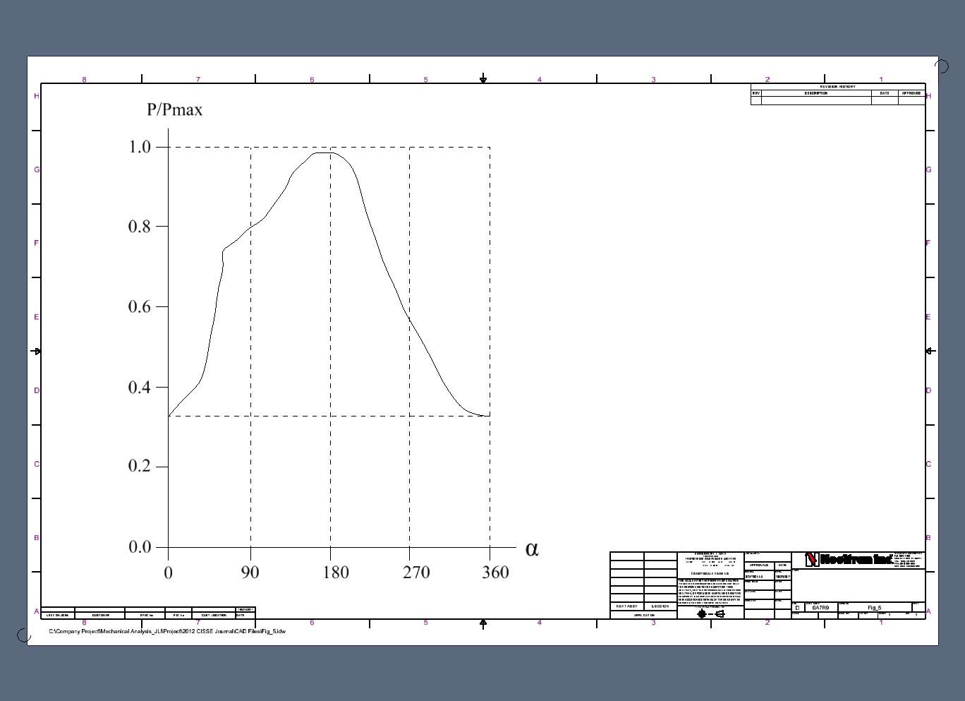 | Figure 5. Pressure ratio P/Pmax vs. crank angle α |
The refrigerating temperature can reach down to 152°K with refrigerating capacity of 385 Btu/hr. The working media is nitrogen and crank turning speed is 180 R/min. The refrigerating temperature vs. time is shown in Fig. 4. The other parametric function curves are also determined by computer-aided modeling and numerical simulation. The P/Pmax vs. α is indicated in Fig. 5. The indicator cards in expansive chamber and full system are depicted in Fig. 6 and 7. The mass distributions such as Me in expansive chamber, Mc in compressive chamber and Mk in clearance cavity are presented in Fig. 8. From these figures, we can see that this new regenerative refrigerating system works properly because the changes of refrigerating capacity vs. time, pressure vs. crank angle α, volume vs. crank angle α, and mass distribution vs. crank angle α in this system meet design spec. Also the enclosed area by cyclic curves in expansive cavity shows that the indicator card is acceptable.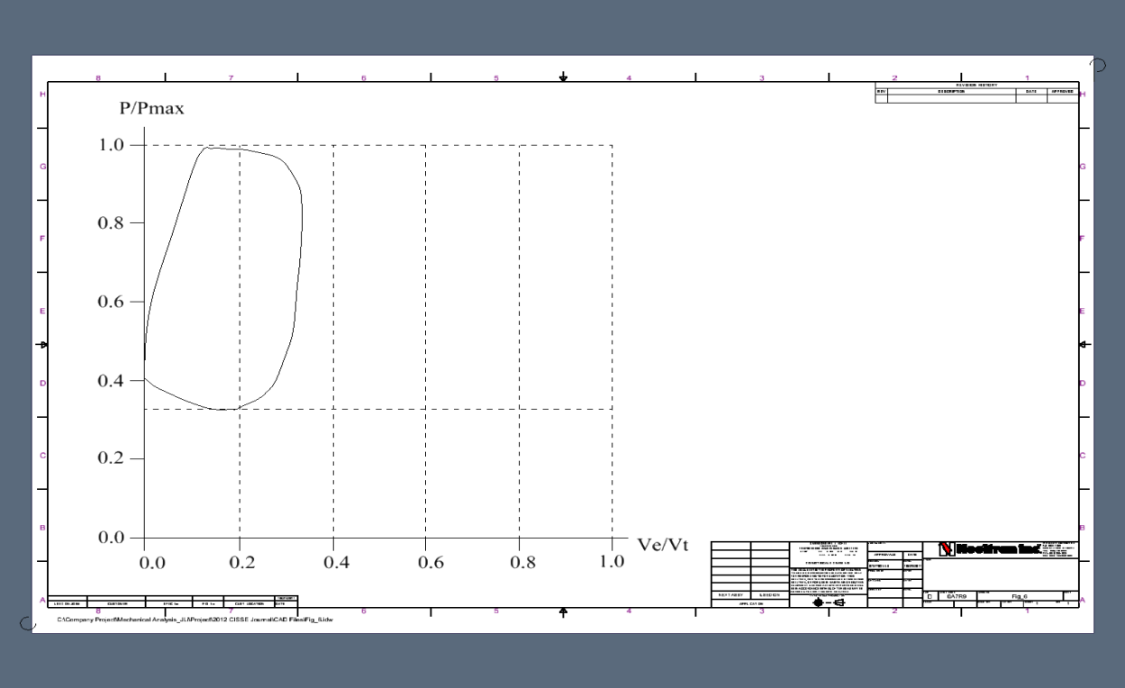 | Figure 6. Pressure ratio P/Pmax vs. volume ratio Ve/Vt in expansive cavity |
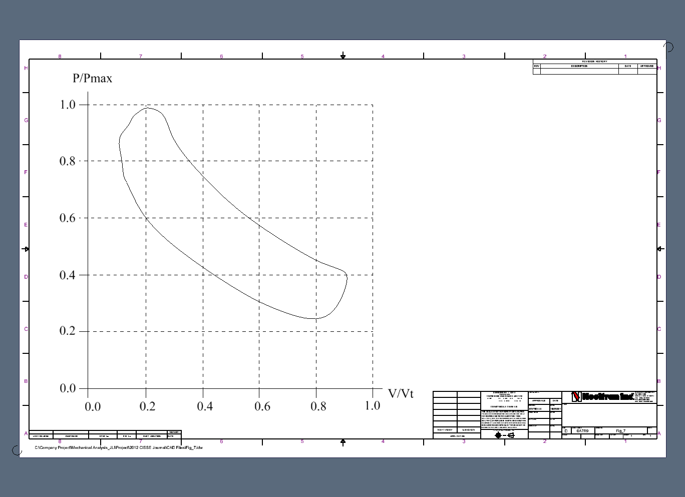 | Figure 7. Pressure ratio P/Pmax vs. volume ratio Vi/Vt in total system |
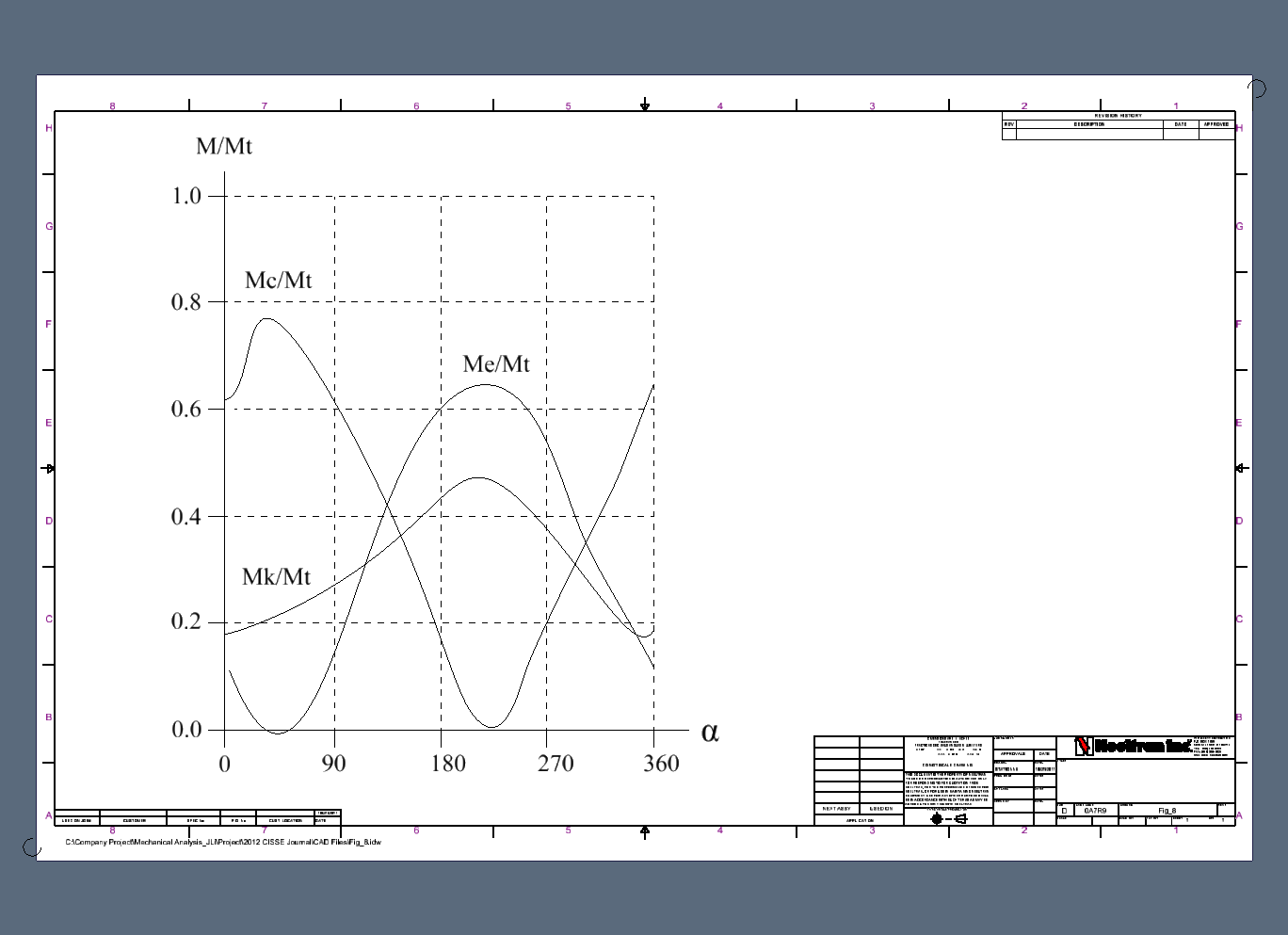 | Figure 8. Mass ratio Mi/Mt vs. crank angle in compressive, expansive, and clearance chambers |
4. Prototype Testing
The prototype of this new refrigerating system has being tested with results shown in Table 1.| Table 1. Testing results of temperature vs. time |
| | Time (min) | Temperature (°k) | | 0 | 297 | | 5 | 291 | | 10 | 272 | | 15 | 255 | | 20 | 235 | | 25 | 217 | | 30 | 193 | | 35 | 185 | | 40 | 177 | | 45 | 171 | | 50 | 165 | | 55 | 159 | | 60 | 155 | | 65 | 153 |
|
|
These testing data are closed to the results from computer- aided modeling and numerical simulation which verifies the feasibility and reliability of this new energy-saving refrigerating system.
5. Conclusions
The feasibility of this new energy-saving refrigerating system has been verified on the basis of thermodynamic study, computer-aided modeling and numerical analysis. The reliable function of this new energy-saving system has also been verified and proved through the prototype testing. The main advantages of this new system include: simple and compact system design, reduced vibration due to its symmetrical structure design, energy-saving due to improved thermal and mechanical efficiency, cost-saving due to low tolerance control in manufacturing of system components, and improved refrigerating capacity due to its cooling capacity being output at both cylindrical ends.
Nomenclature
References
| [1] | Azzouz, K., Leducq, D. and Gobin, D., 2008, “Performance Enhancement of a Household Refrigerator by Addition of Latent Heat Storage”, International Journal of Refrigeration, 31, 892-901 |
| [2] | Liu, J. and Rosato, A., 2005, “Migration of an Intruder in a Boundary Driven Granular Flow”, Journal of Physics Condensed Matter 17, 2609-2622 |
| [3] | Pearson, A., 2007, “Refrigeration with Ammonia”, International Journal of Refrigeration, 31, 545-551. |
| [4] | Mehling, H. and Cabeza, L., 2008, “Heat and Gold Storage with PCM”, Springer, ISBN-13: 978354685562, 254-283. |
| [5] | Sharma, S. and Sagara, K., 2005, “Latent Heat Storage Materials and Systems: A Review”, International Journal of Green Energy, 2, 18-24. |
| [6] | Lai, W., Duculescu, B. and Phelan, B, 2006, “Convective Heat Transfer With Nanofluids in a Single 1.02-mm Tube”, ASME International Mechanical Engineering Congress, 3, 35-39. |
| [7] | Palm, B., 2007, “Ammonia in Low Capacity Refrigeration and Heat Pump Systems, International Journal of Refrigeration, 31, 709-715. |
| [8] | Zhang, N. and Rosato, A., 2004, “Analysis of Instantaneous Dynamic States of Vibrated Granular Materials”, Journal of Mechanics Research Communications, 31, 525-544. |
| [9] | Wang, F., Maidment, G., Missenden, J. and Tozer, R., 2007, “The Novel Use of Phase Change Materials in Refrigeration Plant, Part 3: PCM for Control and Energy Saving”, Journal of Applied Thermal Engineering, 1-8. |
| [10] | Paksoy, H., 2007, “Thermal Energy Storage for Sustainable Energy Consumption – Fundamentals, Case Studies and Sedign”, Springer, ISBN-10 1-4020-5288-X, 357-378. |
 Abstract
 Reference
 Full-Text PDF
 Full-Text HTML