-
Paper Information
- Next Paper
- Previous Paper
- Paper Submission
-
Journal Information
- About This Journal
- Editorial Board
- Current Issue
- Archive
- Author Guidelines
- Contact Us
Journal of Laboratory Chemical Education
p-ISSN: 2331-7450 e-ISSN: 2331-7469
2018; 6(4): 69-76
doi:10.5923/j.jlce.20180604.01

Energetic Particle Emission in Pd/D Co-deposition: An Undergraduate Research Project to Replicate a New Scientific Phenomenon
 Abstract
 Reference
 Full-Text PDF
 Full-text HTML
Pamela A. Mosier-Boss1, Lawrence P. Forsley2
1GEC, 5101B Backlick Rd., Annandale, Virginia 22003, United States
2University of Texas Austin, Nuclear Engineering Teaching Lab, Pickles Research Campus, R-9000, Austin, Texas, United States
Correspondence to: Pamela A. Mosier-Boss, GEC, 5101B Backlick Rd., Annandale, Virginia 22003, United States.
| Email: |  |
Copyright © 2018 The Author(s). Published by Scientific & Academic Publishing.
This work is licensed under the Creative Commons Attribution International License (CC BY).
http://creativecommons.org/licenses/by/4.0/

The experiments described here were part of independent research projects done by different groups of upper division, chemical engineering undergraduate students over a three year period. The purpose of these experiments was to replicate track formation in solid state nuclear track detectors (SSNTDs) resulting from Pd/D co-deposition and to rule out a chemical origin for the tracks. The experiments took several weeks to run. Not only did the students learn about the importance of replication in science, they were introduced to metal electroplating and Faradaic efficiency as well as the use of solid state nuclear track detectors (SSNTDs) and their analysis using optical microscopes. The students also had the opportunity to use freeware programs to model tracks in SSNTDs and calculate linear energy transfer (LET) curves to determine energy loses of energetic particles as they traverse through matter. Most importantly, the experiments demonstrated the importance of using controls and simulations to test a hypothesis, especially for experiments that give unexpected, or anomalous, results whose origins are only understood later.
Keywords: Replication, Reproducibility, Controls, Simulations, New Scientific Phenomena
Cite this paper: Pamela A. Mosier-Boss, Lawrence P. Forsley, Energetic Particle Emission in Pd/D Co-deposition: An Undergraduate Research Project to Replicate a New Scientific Phenomenon, Journal of Laboratory Chemical Education, Vol. 6 No. 4, 2018, pp. 69-76. doi: 10.5923/j.jlce.20180604.01.
Article Outline
1. Introduction
- On March 23, 1989, Pons and Fleischmann announced that their Pd/D electrochemical cells were producing more heat than could be accounted for by chemical means. They speculated that the heat had a nuclear origin. Many laboratories world-wide attempted to replicate the Fleischmann-Pons results. Some succeeded but many more failed. Knowing that one of the key issues to initiate the effect was a high deuterium loading within the Pd lattice, our group developed the Pd/D co-deposition process. The original Fleischmann-Pons experiment electrolytically loaded a bulk Pd electrode with deuterium. Depending upon the size of the Pd cathode, this process could take weeks or months to fully load the Pd cathode with deuterium before the effect could occur. In Pd/D co-deposition, working and counter electrodes are immersed in a solution of palladium chloride and lithium chloride in deuterated water. To assure high deuterium loading in the palladium deposit, the counter electrodes must not absorb deuterium. When a current is applied, Pd metal plates out on the cathode in the presence of evolving deuterium gas and a high degree of deuterium loading (D/Pd ≥ 1) is achieved instantly [1, 2]. Using the Pd/D co-deposition process, we and others have reported, in peer-reviewed journals, on the production of excess heat [3-6], tritium [7-9], and energetic particles [10-16]. The process to generate energetic particles has been patented [17]. As was aptly demonstrated by the Fleischmann-Pons events in 1989, two necessary requirements to achieve acceptance in the scientific community of a new phenomenon are replications and reproducibility. To this end, we approached chemistry professors at a local university asking them if they would be willing to replicate our results of track formation in solid state nuclear track detectors (SSNTDs) as a result of Pd/D co-deposition. The professors thought it would be a good exercise for a group of their undergraduate students to do as part of their independent research project. So, over a period of three years, different groups of senior undergraduate students replicated our Pd/D co-deposition process and obtained tracks in solid state nuclear track detectors. Controls and simulations were done by the students to rule out a chemical explanation for the tracks. We provided the students with chemicals, a protocol, and copies of pertinent publications. The students conducted the experiments independently of us and came up with their own conclusions. One group of students actually presented their results at a National ACS meeting and at an international symposium [18].
1.1. Summary of CR-39 Results Obtained as a Result of Pd/D Co-deposition
- CR-39, an allyl diglycol carbonate SSNTD, was used to detect the energetic particles [19]. When an energetic particle traverses through the plastic, it creates along its ionization trail a region that is more sensitive to chemical etching than the rest of the bulk. After treatment with an etching agent, tracks remain as holes or pits in the plastic. The size and shape of the tracks provide information as to what type of particle created the track as well as its energy. In our experiments, the Pd/D co-deposition reaction was performed with the cathode in contact with the CR-39 detector. Because energetic particles lose energy as they travel through the palladium lattice and solution film between the cathode and detector, placing the detector in close proximity to the detector increases the probability of detecting these energetic particles. This is discussed in greater detail in section 3.4.At the end of these experiments, the CR-39 detectors were etched. Pits were observed in the detector that were coincident with the placement of the palladium deposit on the cathode (Figure 1) indicating that the palladium deposit is the source of the pitting [11, 12]. Microscopic examination of the pits show that they are either circular or elliptical in shape, Figure 2. When focused on the surface of the detector, the pits are dark in color. Focusing the microscope optics inside the pits reveals bright spots. These bright spots indicate the endpoints of the particles that enter the detector and are caused by the curved bottom of the track acting like a lens when the detector is backlit [19]. The color, shape, and bright spot inside are features consistent with those observed for nuclear generated particle tracks. We conducted a series of experiments that showed that the pits observed in the CR-39 detectors used in Pd/D co-deposition experiments were not due to radioactive contamination nor were they due to either mechanical or chemical damage [11, 12]. Figure 1 shows a photograph of a CR-39 detector used in a control experiment that substituted copper chloride for palladium chloride. The same plating procedure was used for both Pd/D and Cu/D co-deposition experiments. As can be seen from the photograph, no pits were observed on the CR-39 detector used in the Cu/D co-deposition experiment. Control experiments will be discussed in greater detail in section 3.2. As shown in Figures 1 and 2, the density of pits is very high in CR-39 detectors used in Pd/D co-deposition experiments. This is due to the fact that CR-39, like photographic film, is an example of a constantly integrating detector. When an event occurs, it is permanently stamped on the surface of the detector. Consequently events accumulate with time and do not get averaged away as what happens with electronic detectors. The high density if tracks is not indicative of a high generation rate.
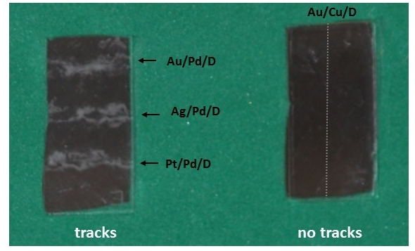 | Figure 1. Photographs of etched CR-39 detectors used in Pd/D co-deposition (left) and a control using Cu/D co-deposition (right). Pd was plated, simultaneously, on Au, Ag, and Pt wires. The positions of the wires are indicated. The gray dotted line indicates the position of the Au wire used to plate out the Cu |
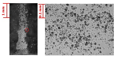 | Figure 2. Microphotographs of etched CR-39 detectors used in Pd/D co-deposition at 20 (left) and 200 magnification (right). Pd was plated, on a Ag wire. Spot in the 20 photomicrograph where of 200 image was taken is indicated with a red circle |
1.2. Summary of Lessons Learned by the Students
- Science is supposed to be thought provoking and to encourage independent thinking. To this end, the students learned about the scientific method, particularly the need to design experiments to minimize possible errors in interpretation especially for experiments that give unexpected results. They learned that this is usually achieved through the use of scientific controls [20]. A scientific control is an experiment or observation designed to minimize the effects of variables other than the single independent variable. This increases the reliability of the results, often through a comparison between control measurements and other measurements. As such, scientific controls are an important part of the scientific method.As a result of their metal electroplating experiments, the students learned about Faradaic efficiency. They also learned about the use of solid state nuclear track detectors (SSNTDs) and their analysis using optical microscopes. They used freeware programs to model tracks in CR-39 to estimate the energies of the particles responsible for the tracks as well as linear energy transfer (LET) analysis to determine energy loses of energetic particles as they traverse through matter. From the LET analysis, the students were able to estimate the energies of the particles when they were formed. The LET analysis also allowed the students to simulate the effect of water on the energetic charged particles. But more importantly, these experiments opened the students to possibility that nuclear reactions can occur inside a metal lattice.
2. Methodology
2.1. Experimental Procedure
- In the Pd/D co-deposition process, an anode and cathode are immersed in a solution of palladium chloride and lithium chloride in deuterated water. The cathode material is chosen to be a metal that does not absorb deuterium. When current is applied, palladium metal plates out on the cathode in the presence of evolving deuterium gas. Palladium readily absorbs hydrogen at room temperatures to form palladium hydride [21]. Consequently, in the Pd/D co-deposition process, the palladium metal lattice instantly loads with deuteria. In these experiments, the Pd/D co-deposition reaction was performed with the cathode in contact with the CR-39 detector. Because energetic particles lose energy as they travel through the palladium lattice and solution film between the cathode and detector [22], the detector needs to be in close proximity to the detector in order to detect these energetic particles. A potentiostat, operated galvanostatically, is used to plate out the metal and electrolyze the deuterated water. The plating procedure used for both Pd/D co-deposition and the control is described in the Supplementary Material. To determine Faradaic efficiency of the metal plating, the students need to know the amount of metal ions originally present in solution and the amount of time spent at each current during the plating phase. The students did a control experiment to verify that the tracks observed in CR-39 detectors as a result of Pd/D co-deposition are due to energetic particles and not chemical/mechanical damage or radioactive contamination. Finally the students examined the tracks in the CR-39 detectors using an Eclipse E600 epifluorescent optical microscope (Nikon) equipped with a CoolSnap HQ CCD camera (Photometrics). Digital images at magnifications of 20, 200, 500, and 1000 were obtained.
2.2. Hazards
- Experiments should be conducted in a well ventilated fume hood as D2, O2 and Cl2 gases are generated. The production of energetic particles is not a hazard, in part because the generation rate is low [11, 12]. Linear energy transfer (LET) analysis (discussed in greater detail in the section 3.4) indicates that the solution and cell components will moderate the charged particles and they will not escape the cell [22]. The detectors also respond to neutrons. However, these neutrons can only be detected by CR-39 because it is a constantly integrating detector. As such, no signal gets averaged away. In these experiments, the total dose is less than the annual radiation dosage experienced by airline workers. This experiment uses hot 6.5 M NaOH solution to etch CR-39 detectors. Appropriate safety procedures to handle etching are described in the Supplementary Material.
2.3. Unusual Materials Needed
- The experiment requires construction of an electrolytic cell, anode, and cathode for the metal electroplating in addition to standard laboratory equipment. Chemicals are readily available from any chemical supplier. Complete descriptions and drawings/photographs of the equipment are given in the Supplementary Material.
2.4. Implementation
- The Supplementary Material contains the information that was provided to the students. They were also provided with PdCl2, CuCl2, D2O, Pt and Ag wires, CR-39, and copies of pertinent publications [11, 12]. It was the responsibility of the students to implement the activity and set up their own timelines. The students obtained a potentiostat, constructed the cells, ran the experiments, and etched the detectors. There were weekly discussions with the students to assess their progress and to provide mentoring. Images of the etched detectors were obtained using our optical microscope.
3. Results and Discussion
3.1. Faradaic Efficiency
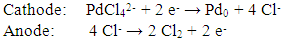
- Faradaic efficiency is the efficiency with which charge (electrons) are transferred in a system facilitating an electrochemical reaction. During the plating phase, the following electrochemical reactions occur at the cathode and anode:
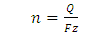
 When operating under constant current mode, the students can easily calculate the amount of material reduced during electrolysis. The students will know the volume and concentration of the metal in the plating solution so they will know how many moles of metal ion they have present. As the current will be changed during the course of the experiment, the students need to keep track of the amount of time spent at each current. They can then use the following equations to calculate the moles of material that have been electrolytically reduced:
 | (1) |
 | (2) |
3.2. Control Experiments
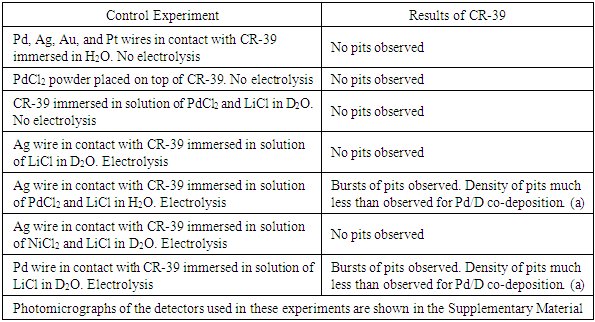
- Formation of tracks in CR-39 detectors used in Pd/D co-deposition experiments has been extremely reproducible [11, 12, 14-16]. However, control experiments need to be done to show that the tracks are not due to either environmental radioactive contamination or mechanical/chemical damage. In a control experiment, an independent variable is the only factor that is allowed to be adjusted, with the dependent variable as the factor that the independent variable will affect. Our experience has shown that, for energetic particles to form, a metal needs to absorb deuterium. A suitable control experiment would be to plate out a metal that does not absorb deuterium. The students did an electroplating experiment using copper chloride instead of palladium chloride. For both copper chloride and palladium chloride, the same electrochemical reactions occur at the anode and cathode. Specifically, oxygen and chlorine gas evolution occurs at the cathode while deuterium gas evolution, hydroxide formation, and metal electroplating occur at the cathode. In addition, the resultant copper and palladium metallic deposits exhibit similar dendritic morphologies. The only significant difference is that palladium absorbs deuterium and copper does not. After etching the detectors, the students obtained similar results as those shown in Figure 1, i.e., tracks were obtained in the Pd/D experiment but not in the Cu/D experiment. From these experiments the students concluded that the tracks observed in the PdCl2 experiment cannot be attributed to a chemical species attacking the surface of the detector. If this were the case, the CR-39 detector used in the CuCl2 experiment would have exhibited cloudiness and pitting, which it did not. The results also indicate that the copper dendrites did not pierce into the detector. Overall, the observed pitting in the Pd/D system is not due to either radioactive contamination or chemical/mechanical damage of the CR-39 detector. Microscopic examination, described in section 3.3, provided further evidence that the tracks were nuclear in origin.If time permits, additional control experiments can be done by the students to increase the level of confidence that the tracks observed in CR-39 detectors used in Pd/D co-deposition are not due to either radioactive contamination or to chemical/mechanical damage. These experiments and the results that have been observed are summarized in Table 1. These control experiments could also be done as a class project. Different groups of students could perform different control experiments. Some groups could even do the same experiments (control or Pd/D co-deposition) to test reproducibility. The students would then share their results with each other. They could then discuss the results of each experiment and what it means in terms of supporting or not supporting the notion that nuclear processes, and not chemical/mechanical processes or radioactive contamination, are responsible for the formation of tracks/pits in the SSNTD. This exercise would teach the students the effort required to verify a hypothesis.
|
3.3. Microscopic Examination of CR-39 Detectors
- The etched detectors were examined by students using a microscope equipped with a CCD camera. Tracks were observed in the detectors used in the Pd/D experiment but not the Cu/D experiment. Figure 3 shows examples of photomicrographs obtained for a CR-39 detector used in a Pd/D co-deposition experiment done on a silver wire. Figure 3a shows an image of the pits obtained at 500 magnification. Dark circular and elliptical pits are observed. Figures 3b and 3c show images of the same region of the detector obtained at 1000 magnification. To obtain the image shown in Figure 3b, the microscope optics were focused on the surface of the detector. The photomicrograph shown in Figure 3c is an overlay of two images taken at two different focal lengths (surface and the bottom of the pits). When focusing deeper inside these black pits, bright spots are observed that are due to the bottom tip of the track. The students learned that the optical contrast, circular/elliptical shape, and bright spot in the center of the pit are attributes of real particle tracks that are used to differentiate them from false events, which are lighter in appearance and irregular in shape [19, 23].
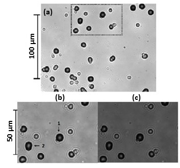 | Figure 3. (a) 500x magnification of pits obtained on a CR-39 detector in contact with Ag/Pd cathode. (b) and (c) 1000x magnification of the region indicated in (a) where (b) was obtained with the microscope optics focused on the surface and (c) is an overlay of two images obtained at different focal lengths (surface and bottom of the pits) |
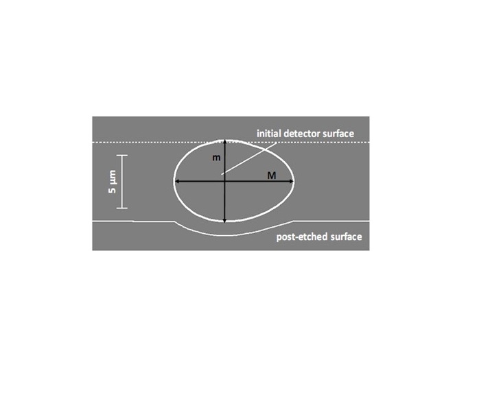 | Figure 4. The shape of track ‘2’ in Figure 3b calculated using TRACK-TEST. Results of analysis: major axis (M) measured = 9.2 ± 0.4 μm, calculated = 9.20 μm and minor axis (m) measured = 7.4 ± 0.4 μm, calculated = 7.63 μm |
3.4. LET Analysis and Simulation of the Effect of Water on Energetic, Charged Particles
- Figure 5 shows a schematic describing the layers a charged particle has to negotiate before it impacts the CR-39 detector. After its birth, a charged particle has to exit the metal lattice and cross a thin water layer before it impacts the CR-39 detector. SEM analysis of the Pd deposit formed as the result of the co-deposition shows that the deposit has a cauliflower morphology which will trap pockets of water. It should be noted that if the Pd had been plated out using higher current densities, the deposit would have flaked off.
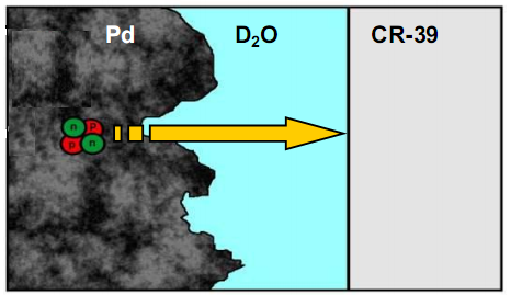 | Figure 5. Schematic describing the layers a charged particle has to negotiate before it impacts the CR-39 detector |
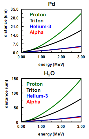 | Figure 6. LET curves calculated for charged particles traversing through palladium and water |
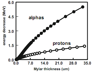 | Figure 7. LET curves calculated for alphas and protons as a function of Mylar thickness |
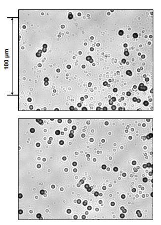 | Figure 8. Photomicrographs obtained at 500 magnification for (top) Pd/D co-deposition tracks and (bottom) ~1 MeV alpha tracks |
4. Conclusions
- The experiments described here were conducted by three separate groups of upper division, college undergraduate students in chemical engineering as part of independent research projects that explored metal electroplating. While the students learned about Faradaic efficiency and the use of optical microscopy to analyze tracks in SSNTDs, they learned about the vigor required to test a hypothesis. In particular, these experiments introduced the students to the importance of using control experiments and simulations to verify a hypothesis, namely that the tracks observed in CR-39 detectors were due to energetic particles and not chemical/mechanical damage. The goal of this communication was not to prove whether or not nuclear reactions can occur inside a metal lattice, but rather to show that undergraduate research projects can be used as a new paradigm to vet new phenomena/ideas without prejudice.
5. Supporting Information
- Detailed student procedures to do the electrolysis experiments and etching of the CR-39 detectors are available in this issue online. Included are drawings and photographs for assembling the electrodes and cells as well as examples of representative tracks observed in CR-39 detectors used in Pd/D co-deposition experiments. Screen shots explaining how to use TEST-TRACK and SRIM-2013 are also included. Supplementary Material.pdf
ACKNOWLEDGEMENTS
- We would like to thank the students who did the metal electroplating experiments as well as Prof. Jan Talbot and the chemical engineering department of University of California San Diego for allowing the students to conduct these experiments. Thanks are given to Steve Krivit of New Energy Times for providing support to the students to present their results at the spring American Chemical Society meeting in 2009.