-
Paper Information
- Next Paper
- Paper Submission
-
Journal Information
- About This Journal
- Editorial Board
- Current Issue
- Archive
- Author Guidelines
- Contact Us
Journal of Laboratory Chemical Education
p-ISSN: 2331-7450 e-ISSN: 2331-7469
2018; 6(3): 47-59
doi:10.5923/j.jlce.20180603.01

H2fromH2O: A Water-Splitting Kit with Instructional Applications in Secondary Education
 Abstract
 Reference
 Full-Text PDF
 Full-text HTML
Ryan T. Pekarek, Aubrey L. Bleier, Eileen R. Sullivan, Elizabeth A. Bevan, Olivia Ursi, Thurman H. Rose, Michael J. Rose
The Department of Chemistry, The University of Texas at Austin, Austin, TX, USA
Correspondence to: Michael J. Rose, The Department of Chemistry, The University of Texas at Austin, Austin, TX, USA.
| Email: |  |
Copyright © 2018 The Author(s). Published by Scientific & Academic Publishing.
This work is licensed under the Creative Commons Attribution International License (CC BY).
http://creativecommons.org/licenses/by/4.0/

A simple electrochemical device (ammeter) has been developed to perform the electrolysis of water (2 H2O → 2 H2 + O2) for the purpose of hands-on instruction for chemistry courses at the middle and high school levels. In contrast to the ‘historical’ experiment – which involves the use of glass barometers, expensive platinum wire and strong acids – the present experiment utilizes inexpensive polypropylene tubes, nickel wire and a safe pH 7 electrolyte. The present device includes an easy-to-control potentiometer to regulate the electrolysis and an ammeter to monitor the current, which is incorporated onto a printed integrated circuit board for ease of assembly. The kit can also drive the electrolysis with a hobby solar panel that generates sufficient current for water electrolysis under 1-sun illumination. We developed lesson plans based on water-splitting for secondary education to integrate sustainable energy into modules teaching stoichiometry and the ideal gas law (introductory level), as well as electrochemistry at the advanced placement level – thus improving the scope and depth of the lesson. The lesson plans also emphasize aspects of renewable energy, solar energy and the topic of precious versus earth abundant elements. The electrolysis kits have been utilized to date by more than 30 instructors (in schools) in southern California and central Texas, spanning both intermediate and secondary schools. The kit also provides a mechanism for interaction of high school students and other young learners with university faculty, staff and STEM-promoting organizations.
Keywords: Solar fuels, Water splitting, Electrochemistry, High school, Energy literacy, Chemical education
Cite this paper: Ryan T. Pekarek, Aubrey L. Bleier, Eileen R. Sullivan, Elizabeth A. Bevan, Olivia Ursi, Thurman H. Rose, Michael J. Rose, H2fromH2O: A Water-Splitting Kit with Instructional Applications in Secondary Education, Journal of Laboratory Chemical Education, Vol. 6 No. 3, 2018, pp. 47-59. doi: 10.5923/j.jlce.20180603.01.
Article Outline
1. Introduction
- World energy demand is expected to double its 1990 value by 2040 [1]. To meet this growing need without incurring the side-effects of fossil fuel extraction and consumption, renewable energy has become an important technological and public initiative [2]. As of 2016 energy efficiency, green vehicle production, renewable energy production, and other clean energy-related careers employ 2.5 million workers in the United States alone [3]. To prepare students for this growing labor market and to make informed personal and public decisions, educators are encouraged to integrate energy literacy into their curricula in order to improve student attitudes and knowledge [4, 5]. Science, and especially chemistry, classrooms are an excellent place to incorporate energy lessons as many concepts align with existing guidelines. For example, core principles in the physical sciences include defining energy and understanding its conservation and transfer through various chemical and physical processes – aligning with fundamental concepts of energy literacy [4, 6]. Further, as students’ interest in science declines in high school, hands-on experiments that improve students’ attitudes and motivations are needed to improve the effectiveness of education regarding both science and renewable energy [5, 7].One important energy conversion – solar to chemical fuels – has been the subject of significant research in the last decade, especially the holy grail reaction of solar-driven water splitting [8]. This classic reaction – the electrolysis of water to its elemental components, H2 and O2 – was first investigated in 1797 by Dutch scientists A. Paets van Troostwijk and Jan Rudolph Deiman, and formed the basis of many pioneering electrochemical experiments [9, 10]. Since its discovery, water splitting was the subject of many critical studies, but the utility of the reaction toward renewable fuel production was limited by the energy (that is, applied potential) required to drive the reaction. Famously, Japanese chemists Akira Fujishima and Kenichi Honda overcame this barrier in 1972 when they reported photoelectrochemical (PEC) water splitting powered by ultraviolet light using TiO2 – realizing the possibility of solar-powered electrolysis [8, 11]. For the better part of the 20th century, chemistry [12-16], and physics [17] students around the world were exposed to water electrolysis in secondary education and university general chemistry courses to demonstrate concepts such as kinetics [18], inorganic and materials chemistry [19, 20], catalysis [18, 21, 22], renewable energy [15, 21, 23], and – of course – electrochemistry [16]. Conventionally, the experiment was performed using platinum (Pt) wire, dilute or concentrated sulfuric acid, and a glass manometer [24]; advanced experiments use TiO2 to replicate the original Fujishima/Honda experiment as well [23]. Although this apparatus was appropriate for classroom demonstrations at the secondary education level and hands-on experiments at the university level, it has several drawbacks that prevent widespread implementation. The most notable disadvantages are the high expense of Pt wire, the handling risks associated with sulfuric acid (or other acidic media), and the risk associated with delicate glassware.In this work, we have developed an educational water-splitting kit with optimized and low-cost components for repeated application in an educational setting. In our outreach efforts, we utilize a printed integrated circuit (IC) board that safely controls the current delivered to the electrolysis – allowing the students to experimentally observe the relationship between current and gas production both qualitatively and quantitatively. The IC board is powered by a commercially available AC/DC (120 VAC→12 VDC) converter. We also provide additional information for the use of a hobby solar panel that can be used to demonstrate the principle of the solar→H2 application. Lastly, in order to facilitate the integration of energy literacy concepts into existing chemistry and physical science curricula, we present a number of lesson plans consistent with state and national educational benchmarks to assist instructors in the integration of the hands-on experiment with existing lessons.
2. Experimental
2.1. Chemicals and Materials
- Electrode wires were obtained from Sigma-Aldrich (Fe, 0.5 mm; Ni, 0.5 mm; Co, 1.0 mm), Goodfellow (Cu, 0.5 mm; Zn, 0.5 mm; V, 0.5 mm; Ti, 0.5 mm) and Alfa Aesar (Pt, 0.25 mm). The 15 mL polypropylene tubes (Falcon), tall-form 400 mL beakers, sodium sulfate, hydrochloric acid and sodium hydroxide were obtained from Fisher Scientific. The integrated circuit was designed in the Diptrace software program and manufactured by SunStone, Inc. The hardware components were assembled onto each amperostat (termed ‘electrostation’ throughout this work) in the UT electronics shop. The circuit included a heat sink, such that a circuit test loop could be included in the final design. In this way, the integrity of electronics (i.e. ‘smoke test’) could be performed in the absence of any electrolysis or chemical reagents. This has proven useful as a quality control check after the initial assembly of the devices and during continued operation throughout outreach activities. Electronics components were purchased from Digikey and Radio Shack. The kits were powered by 2.5 A 120 V (DC) → 12 V (DC) Enercell converters purchased from Radio Shack (Cat# 273-318) and alligator clips were used to connect the electrodes to the electrostation (Radio Shack, #2781156). For solar-powered operation, multicrystalline silicon PV solar panels (5 W, 12 V) were purchased from UL-Solar (model: STP005P).
2.2. Electrode-Tube Assembly
- Gas-capture electrodes were fabricated by drilling a 1 mm hole in a 15 mL polypropylene tube. For each metal, a 13 cm length of wire was fed through the hole and was positioned such that that ~1 cm of wire protruded from the conical end of the tube (for making electrical contact) while the other end extended slightly less than the entire length of the tube (evolution of gas emanates primarily from the bottom tip of the electrode). The electrode-tube assembly was secured and the hole sealed with 5-minute epoxy (Loctite Instant-Mix Epoxy). After curing, pairs of electrode-tubes were fastened together with two plastic zip-ties, one at each end of the tubes (see Figure 1).
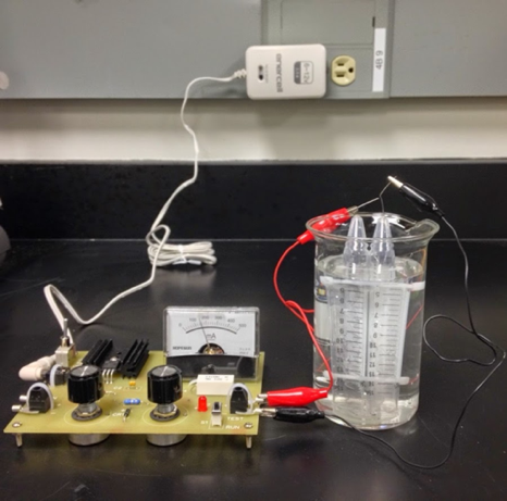 | Figure 1. Assembly of the ‘electrostation’ and electrolysis apparatus |
2.3. Electrostation Operation
- To examine the performance and stability of multiple metal wires at various pH’s, conventionally strong acid (0.5 M H2SO4) or base solutions (1 M NaOH), as well as a classroom-friendly electrolyte (1 M Na2SO4) were paired with each metal electrode tested. Three electrolyte solutions were prepared using tap water at UT Austin in volumes necessary for a given experiment or demonstration. The paired electrode-tubes (the assembly described above) and the tall-form 400 mL beaker were filled with the solution. The beaker was filled ¾ full, while the tubes were filled to the top. The beaker and the electrode-tubes were held at a 45° angle, and the electrode-pair was quickly inverted and submerged into the solution. Generally, several attempts were necessary to ensure that ≤1.5 mL of headspace gas was attained. Electrical contact from the electrostation to the two wires of the electrode-tube assembly was achieved with coated wire leads and alligator clips. The electrode-tubes connected to the negative contact served as the cathode, while the electrode-tubes connected to the positive contact served as the anode. To initiate the electrolysis, the power adaptor was connected to the electrostation and the two switches were set to ‘on’ and ‘run’ (‘test’ mode was used to assess the internal circuit). The two knobs (fine and course control) modulated the current through the device. Figure 1 depicts the assembled device and a detailed pictoral description of the above steps may be found in Appendix A.
2.4. Electrode Optimization
- To determine the optimal metal to use in the construction of the electrode-tubes, electrolysis was performed using several metals. Two series of experiments were performed to optimize the cathode and anode independently of the other electrode. To isolate the performance of one electrode, a platinum counter-electrode tube was used to operate opposite to each metal of interest. For example, in the anode optimization experiments the Pt electrode-tube was attached to the negative port (acting as the cathode) while the experimental metal electrode-tube was attached to the positive port (acting as the anode). To optimize the cathode, the arrangement was reversed. All experiments were performed at the maximum current setting. With proper assembly of the electrolysis kit, bubbles were observed evolving from both the cathode and anode, indicating the production of H2 and O2, respectively. During electrolysis, the increasing volume of gas displaced the solution from the tube, and the volume of water remaining in each tube was recorded at one-minute intervals for time-dependent measurements. As significantly more H2 is produced, electrolysis was performed until the volume of water in the cathode was depleted – at which point the total time and final volumes were recorded. Both the cathode (Ptanode|Xcathode) and anode (Ptcathode|Xanode) were studied for a range of metals (X = Pt, Ni, Zn, Fe, Cu, Co, V, Ti) – and each metal under all three conditions: acidic, neutral, and basic. The total electrolysis time varied depending on the metal and pH used; however, in most experiments the cathode electrode-tube had filled with H2 in ~5-10 min. An average rate of gas production was then calculated for each electrode by dividing the change in water volume of the anode by the total time for electrolysis.
2.5. ‘Super-combination’ Pairs
- At each pH, the most promising Pt|X pairs (stable with a high rate of gas production) were selected to form ‘super-combinations’, where the best-performing Xcathode and Xanode electrodes were paired together. The electrolysis experiment was performed as above, and the rates of electrolysis for the anode and the cathode were determined separately by dividing the change in volume of the respective electrode-tube by the total electrolysis time. A total rate of electrolysis was calculated by summing the anode and cathode rates. Unlike the initial electrolysis experiments, each super-combination was only tested at the optimal pH as suggested by the Pt|X experiments. Some Pt|X (X = Ni, Co) pairs performed well under multiple pH conditions and thereby the analogous super-combinations (Nianode|Nicathode, Nianode|Cocathode) required multiple tests.
2.6. Solar H2 Conversion
- To use the electrostation to demonstrate a truly renewable electrolysis reaction, a solar panel was used to power the electrostation. The same experimental apparatus as described above was employed outside during daytime hours with the solar panel connected in place of the power adaptor. Specifically, a complete circuit was achieved by connecting the solar panel electrical ports to the input ports designed into the circuit board.
2.7. Linear Sweep Voltammetry
- For more characterization of catalytic onset potentials, cyclic voltammetry was used. All voltammograms were collected using a CH Instruments 660A potentiostat. The cell was composed of an SCE reference electrode (CH Instruments), and a graphite counter electrode. All voltammograms have been normalized to the maximum current for the sake of clarity.
3. Results and Discussion
3.1. Electrolyte
- The precedents for the electrolysis of water (2 H2O → 2 H2 + O2) date back more than two centuries, but almost exclusively involve the use of strong acid (i.e. HCl or H2SO4) and platinum wire electrodes [9, 24]. The use of strong base is also extensively used [25]. However, these conditions did not meet our goal of facile use in school, community and STEM organization settings. Firstly, in intermediate or secondary education institutions, strong acids or bases are an added challenge to student/instructor safety and an additional complexity due to proper liquid waste disposal requirements. Secondly, for mobile demonstrations (outreach, learning centers, museums, demonstrations, etc.), the requirement to transport and use concentrated HCl, H2SO4 or solutions of NaOH outside the chemistry lab poses a safety and legal barrier. While we include both H2SO4 and NaOH in this study to demonstrate the fundamental chemistry and properties of the assembly, we sought a third electrolyte solution to ease these safety and logistical considerations. Sodium sulfate is ideal for this purpose as it is forms highly conductive solutions, yet has low environmental and human toxicities (though it should not be consumed) [26-28]. Further, the Clean Water Act allows for the disposal of dilute solutions of simple inorganic salts (such as Na2SO4) down the drain in most areas (providing the sewer leads to a publicly owned water treatment plant) [29]. Notably, this exception does not apply to storm drains or other disposal methods leading directly to the environment. Local water treatment plants should be contacted with questions regarding drain disposal of chemicals. Furthermore, transportation of small amounts of sodium sulfate (< 200 kg) is not federally regulated and is therefore permissible without added complication [30]. Chemical hygiene guidelines maintain that the Na2SO4 should be kept in its original packaging (or another appropriate, well-labeled container) and in a secondary container, accompanied by its Safety Data Sheet [26, 31].
3.2. Anode Metal Selection
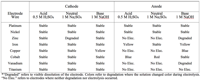
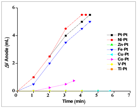
- To optimize the efficiency of the oxidative half reaction, each metal anode was paired with a Pt cathode and electrolysis performed until the volume of water in the cathode tube was replaced by H2 gas. Example plots for each metal at neutral pH are displayed in Figure 2 where the total change in volume of the anode is plotted against the total electrolysis time for each metal. Data from the analogous experiments under acidic and basic conditions can be found in the Appendix (Figures A1 and A3). The average rate of electrolysis was used to make global comparisons between metals at various pH conditions and are displayed in Figure 4 for all metals and conditions studied in this work. The stability information is summarized in Table 2. In acid, no O2 evolution was observed when Zn, Cu, V or Ti was used as the anode. While the Co and Fe anodes did evolve O2, both metals colored the electrolyte solution during electrolysis (blue and yellow, respectively), indicating the metal itself is oxidized and solubilized. Stability results are summarized in Table 1. Further, visible dissolution of the Co anode was observed. Accordingly, only Ni and Pt metals were suitable acidic anodes, evolving 0.7 and 0.6 mL/min of O2, respectively. Under neutral conditions, similar results were obtained with some exceptions. Firstly, the Fe anode was stable during electrolysis and evolved 1.1 mL/min of O2, similar to Ni and Pt (1.3 and 1.2 mL/min, respectively). Secondly, while visible dissolution of the Co anode was still observed, the solution was colored red rather than blue. This observation coincides with the well-known aqueous Co2+ pH-color equilibrium whereby acidic Co2+ solutions favor the anion-bound complex, [Co(SO4)3]4– (blue), and neutral conditions favor the aquo complex, [Co(H2O)6]SO4 (red) [32].
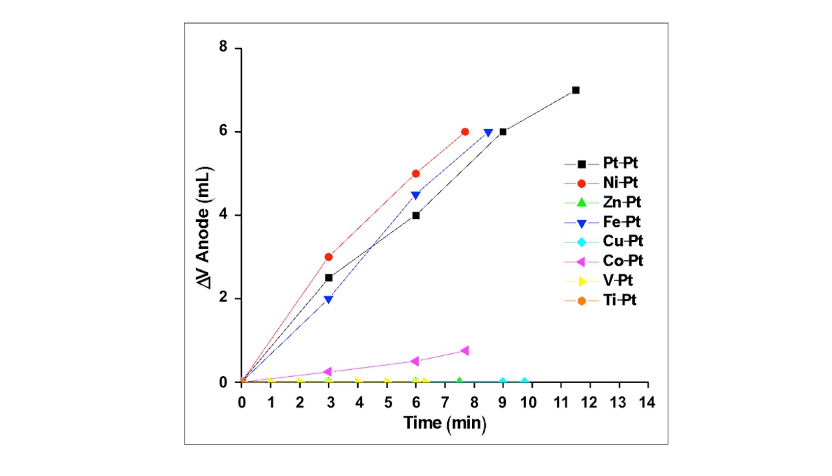 | Figure 2. Volume of O2 produced (mL) plotted against electrolysis time for each Metalanode|Ptcathode combination at neutral pH (1 M Na2SO4) |
|
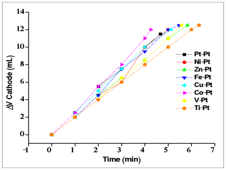
3.3. Cathode Material Selection
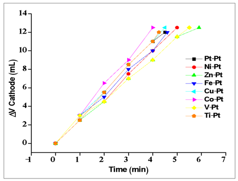
- Each Pt|X combination was also tested where the Pt acted as the anode and the metal of interest, X, as the cathode. Figure 3 depicts the evolution of H2 during electrolysis for each Pt|X pairing, and analogous plots for this series are given in the Appendix under acidic and basic conditions (Figures A2 and A4). Relative to the anodic results, the cathodes displayed less variation between metals and pH conditions as nearly all performed well. In acid, all electrodes evolved H2 at a rate between 1.0 and 1.5 mL/min H2 without signs of degradation. Under the neutral solution, only the Zn cathode visibly degraded (dissolution) and rates increased to 2.0 to 3.25 mL/min H2. Finally, in the basic solution, all cathodes were stable except Fe and Cu, where cathode dissolved or colored the solution yellow. Both Ni and Co were chosen for study in the ‘super-combinations’ (see below) at all pH solutions as they displayed large rates in all solutions. In acidic media, Cu was also selected as the observed H2 evolution rate was similar to cobalt. Platinum was not selected for further study as it would be cost prohibitive on the desired scale.
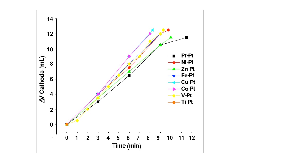 | Figure 3. Volume of H2 produced (mL) plotted against electrolysis time for each Metalcathode|Ptanode combination at neutral pH (1 M Na2SO4) |
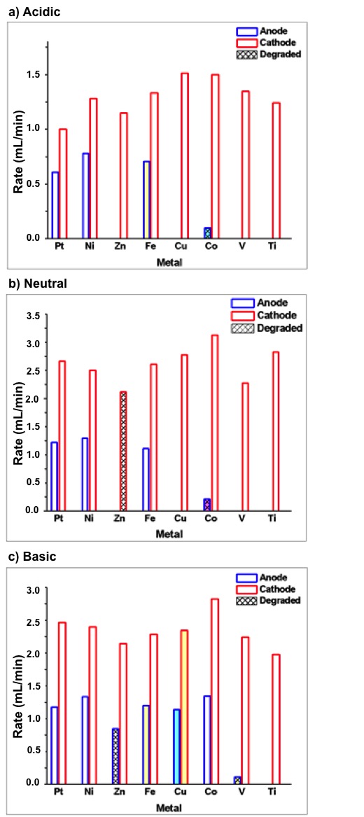 | Figure 4. Rates of electrolysis and color change or degradation observed for each metal at (a) neutral pH (1.0 M Na2SO4), (b) acidic pH (1 M H2SO4), or (c) basic pH (1 M NaOH). Blue bars indicate trials where the metal served as the anode along with a Pt cathode, whereas red bars indicate the opposite. Trials in which the metal degraded without an observed color change are shaded with a diamond pattern. Bars shaded with a color indicate the final color of the solution that was observed during electrolysis. Uncolored bars had no observed color changes |
3.4. ‘Super-combinations’ and Final Device
- We hypothesized that pairing a top-performing anode with a top-performing cathode would enhance the rate of electrolysis and thus explored several ‘super-combinations’ to determine the most efficient device configuration. For each pH condition, the cathode and anode with the highest gas evolution rate was paired. If a second metal had comparable electrolysis rates to the top-performing metal, it was also tested. This resulted in a total of nine cathode-anode pairs as ‘super-combinations’. For example, at neutral pH, the anode that resulted in the highest rate of electrolysis (rate of O2 production) was Ni, and the cathode that resulted in the highest rate of electrolysis (rate of H2 production) was cobalt. These metals were paired as one super-combination. In order to evaluate the function of each electrode separately, as well as compare between super-combinations, the rate of gas evolution at each electrode was recorded and summed to give a total electrolysis rate. The results are shown in Figure 5. As shown, the neutral super-combinations were made of Ni anodes with Cu, Ni and Co cathodes and displayed proper 1:2 volume ratios at the cathode and anode. All neutral super-combinations evolved the least gas when compared to the acidic and basic conditions, and the Cocathode|Nianode combination evolved the most, followed by Cucathode|Nianode and Cocathode|Nianode.
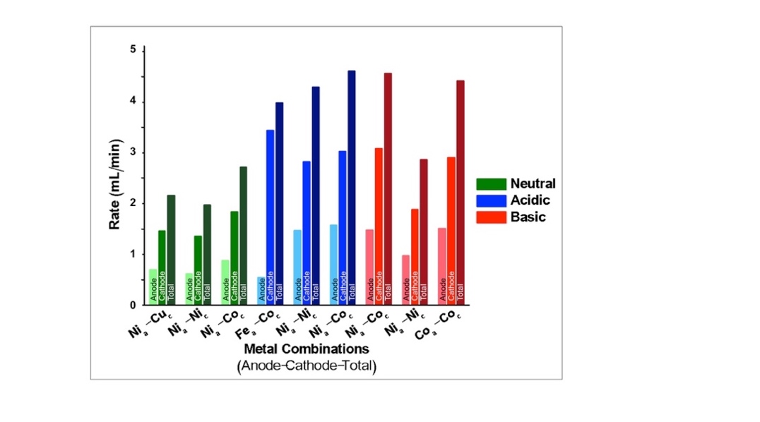 | Figure 5. ‘Super-Combinations’: Average rates of gas production by each super-combination under neutral (green), acidic (blue), and basic (red) conditions. Subscript ‘a’ indicates the metal acting as an anode, while ‘c’ denotes cathode. The left bar (lightest shade) for each super-combination represents the rate of electrolysis at the anode (rate of O2 production), while the middle bar (medium shade) represents that of the cathode (rate of H2 production) and the right bar (darkest shade) represents the sum of both the anode and cathode |
3.5. Solar Experiments
- While most experiments with the electrostation were designed to be used in the classroom powered from wall outlets, the electrostation can also be operated using a solar panel outdoors. An experiment was performed to measure the electrolysis rate when the electrostation was configured with the solar panel (See Experimental Section) and placed under 1 Texas-sun conditions (summer sun at zenith). As mentioned above, the Nicathode|Nianode electrode pair was chosen for use in an educational setting and was therefore selected for use in the solar experiment. Figure 6 depicts the measured current and volume displacement at the anode during electrolysis. Remarkably, in the solar-powered configuration a maximum current of 390 mA was achieved – more than double the current measured when the same configuration was powered by the wall outlet (180 mA). Accordingly, the overall electrolysis rate in the solar experiment (2.96 mL/min H2 + O2) was also larger than the rate indoors (1.36 mL/min). Thus, in an educational setting, this experiment can not only demonstrate that the electrostation can be powered by solar energy, but also that the sun is a powerful and sustainable resource.
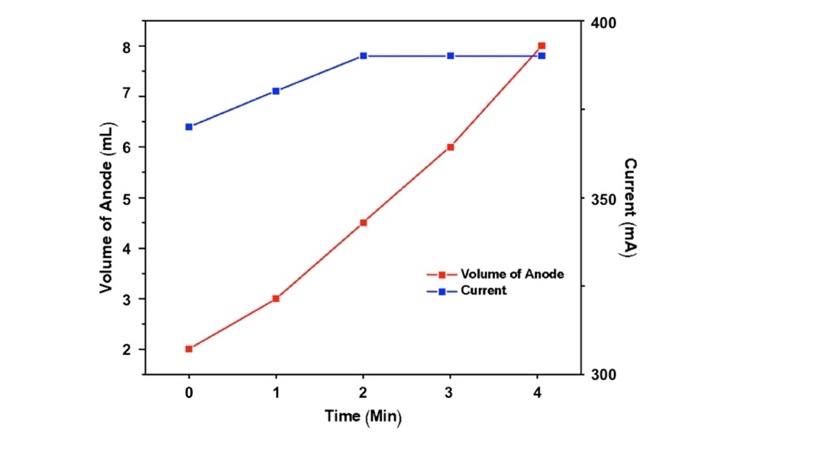 | Figure 6. Observed O2 evolved (red) and the current (blue) during solar electrolysis using the Nicathode|Nianode electrode configuration |
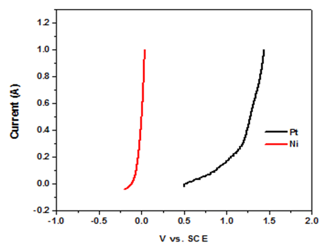
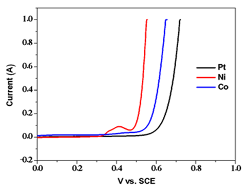
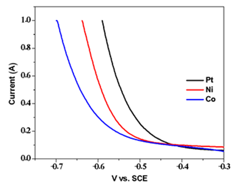
3.6. Linear Sweep Voltammetry
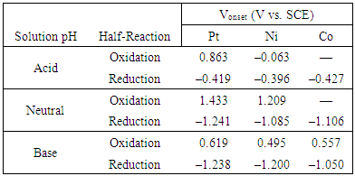
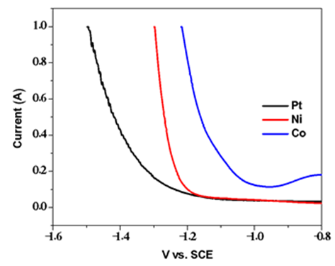
- To analyze the efficiency of each half reaction, linear sweep voltammograms were collected for selected metals: Ni, Co, and Pt. Since Ni and Co were highly effective electrodes, both were selected for the voltammetric study (Co was only included under conditions where it was stable during device operation). Pt was also included for comparison. Figure 7 depicts anodic and cathodic voltammograms under neutral conditions while acidic and basic voltammograms are depicted in the Appendix (A5-8).
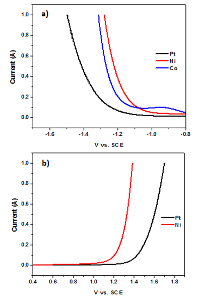 | Figure 7. Linear sweep voltammograms for the reductive (a) and oxidative (b) components of electrolysis under neutral pH. Experimental conditions: 1 M Na2SO4, counter: graphite, reference SCE |
|
4. Educational Implications
4.1. Integration into Middle and High School Curricula
- We sought to supply this experiment to teachers as an educational tool to aid existing lessons while improving student energy literacy. We thus developed a series of lesson plans that integrate energy concepts into existing standards. All lesson plans may be downloaded from our website (www.roseresearchgroup.org/outreach). We designed our lesson plans primarily to meet the needs of Texas educators; therefore, plans were formulated utilizing the Texas Essential Knowledge and Skills, or TEKS, approved by the state legislature beginning in the 2010-2011 school year. These objectives are denoted in the in the lesson plan document available on our website. For the purposes of remaining up-to-date with national initiatives, the relevant Next Generation Science Standards (NGSS) are listed as well. Both will be used to understand how the educational needs of students have been met. TEKS include process objectives, which relate to developing scientific skills and practices, as well as content objectives, which relate specifically to concepts. For instructional purposes, process objectives have been omitted from instructional material to condense the amount of information given to instructors. We have also developed several videos to introduce the concept (which are also available without cost on our website).Our lesson plans follow the 5E model, which represents the different stages in delivery of a lesson to students. These stages include engagement, exploration, explanation, elaboration, and evaluation. We find that this is a method that works well for introducing this hands-on laboratory activity, as it captures student attention and provides opportunities for students to make observations of their own. Electrolysis kits were used for instructional purposes in several local public high and middle schools, one secondary (6th-12th grade) charter school, and one homeschool group. We provided instructional support in the form of lesson plans and undergraduate volunteers to most of these groups. These kits serviced students in grades 6-12, with emphasis at the high school level. Most lessons were implemented in the chemistry classroom, with stoichiometry, types of reactions, and sustainable energy being primary topics of interest.Lessons ranged from 45 to 90 minutes. Students were arranged in groups of 2-4; it is our experience that limiting groups to four students or fewer provides the most opportunity for continued engagement in the activity. For most lessons, after students were introduced to the concept of water-splitting and completed setup of the electrolysis kit, measurements were recorded using from the graduated electrode tubes at regular intervals. This allowed a concept of proportionality to be established and for analysis and development of the balanced equation for water splitting. Instruction then deviated depending on the objectives of the teacher and the time allotted for the experiment. Some teachers elected to perform the same reaction with the supplied solar panel, providing a source of energy to make a connection to topics in sustainable energy. Teachers also utilized a small car (included with the electrostation classroom kit) containing a hydrogen fuel cell to demonstrate the power of hydrogen. Others explored topics in efficiency of the electrolysis kits themselves.Based on verbal and written feedback, teachers expressed positive feedback about their experience using the kits. Several classes used the instructional videos to introduce concept and experiment. Unexpectedly, many teachers also noted the positive effect of having guests from the university in the classroom (either via undergraduate volunteers or by proxy via the video). Nearly all of the feedback from teachers who chose to accept volunteers noted the added excitement and focus from students in response to the classroom guests. Volunteers reported questions from students both related and unrelated to the lesson. Several groups discussed the energy applications of the lesson while others inquired about university life and admissions. Teacher feedback suggests student attitudes toward chemistry and energy concepts improved due to the perceived authority and excitement of the guests in the classroom. The kits were a helpful way to visibly demonstrate the concepts of conservation of mass and stoichiometry, and these themes were the most popular choice of lesson plans by teachers in the general and ‘Pre-Ap’ classrooms. A significant aspect of these lessons involved students observing differences between tubes and explaining the observations. Volunteers often engaged with students and used guided questions to help students understand the stoichiometric 2:1 ratio of hydrogen and oxygen gases. Notably, there was an overwhelmingly positive response from both teachers and students to the solar panel demonstration, generally performed at the end of the session. Students were interested in the absence of external power supply and ability to modulate the gas formation by covering and uncovering the solar panel. Teachers expressed that the solar panel demonstration serves as a capstone to reinforce the lessons taught inside. We received some feedback related to expanding the range of topics covered by the electrolysis kits, which we have done by writing a variety of lesson plans exploring different scientific concepts. While we are enthused, by the success, we also note areas of future improvement. While most students respond with excitement to the production of bubbles in the tube, some students expect more gas evolution, and we have considered building a larger electrostation for this purpose. Further, many students and teachers have remarked that they would like to find uses for the H2 generated during the experiment. While some teachers elect to ignite the small amount of generated H2, safety considerations limit this practice. We have considered developing a H2 storage system and corresponding fuel cell so the H2 may power a device (i.e. a student’s cellphone), but the amount of H2 needed for this use complicates this demonstration. Finally, future development of the electrostations will improve durability, as repairs are often needed after use in the classroom.
4.2. Community Engagement
- Community engagement strategies have been used in parallel with classroom interventions. Presentations have ranged from short (<5 minutes) interactions with individuals of all ages to classroom-style lessons lasting for one hour. One challenge in adapting from the classroom setting to community events is the limited time most participants spend engaging with the activity. In order to shorten the engagement time for each participant, we eliminated device assembly time by preparing the experiment beforehand. When the participant arrived, he/she only needed to add prepare the electrode tubes and connect the alligator clips before initiating electrolysis. This allowed the limited engagement time used elaborating on the scientific concepts behind the electrolysis of water and energy without compromising the participant’s experimental engagement in the activity.Presentations to large groups or groups consisting mostly of young children (<5 years old) relied heavily on observation of change in the reaction. As the experiment, produces a quantifiable amount of gas in a short time, participants without background knowledge of the process of electrolysis of water can observe and visualize the chemical reaction. Most of our engagement of middle and high school students has been in the classroom environment, which is detailed above. With limited time, however, the strategies listed above for elementary school students have worked well to engage older students with the experiment while still allowing for elaboration on higher level concepts such as conservation of mass.Most of our engagement with adults has been a result of their supervision of their children at community events. Indeed, we found that even adults are engaged with the activity, even if their children are not. Adults are able to engage with the material at a higher level as well as easily make connections to current events and issues surrounding renewable energy. Many seemed interested in hydrogen fuel technology in cars and homes, and the look forward to the development of specific adult-oriented engagement strategies.
5. Conclusions
- In this work, we have developed an educational water-splitting experiment designed to teach various common chemistry concepts. We demonstrate a comprehensive evaluation of the components of an educational water-splitting experiment. The nature of the engagement sometimes dictates the need for simplicity, and our results suggest a Nicathode|Nianode configuration at neutral pH is best for this objective, considering possible student error and safety considerations. We have also reported several other configurations so that instructors capable of higher complexity (safety and supervision) may also use the experiment (i.e. Cocathode|Nianode in acid or Cocathode|Coanode in base). We have laid the foundation for the development of future experiments using different metals and suggest these results may also be used to design lessons to integrate the concept of catalysis into advanced chemistry classes. Furthermore, our results suggest that the present experiment may be adapted to incorporate concepts related to catalysis, inorganic reactivity, or electrochemistry. Due to the nature of the lessons, concepts related to sustainable energy are incorporated into student’s learning, moving toward the goal of general energy literacy. Furthermore, the nature of these outreach activities serves to connect communities and grade-school students with professors and researchers at the post-secondary level. We hope this model will continue to grow and be the subject of future inquiry.
ACKNOWLEDGEMENTS
- This research was supported by the Dreyfus Special Programs grant for chemical education (SG-13-042, from 2014-2017), a Cottrell Scholar award to MJR from Research Corporation (RCSA 23640), an NSF-ACC postdoc fellowship to MJR (CHE-1042009, from 2010-2012), and the CCI Solar Fuels program (CHE-0802907, from 2010-2012). AB, EB, and OU gratefully thank Dr. Shelly Rodriguez and the UTeach internship program for their funding and support. The authors would like to thank Mr. Tim Hooper for assembling and repairing the circuit boards, and Ms. Deena Telley of Austin High School for her feedback, insight, and use of her classroom.
Appendix A. Electrostation Assembly
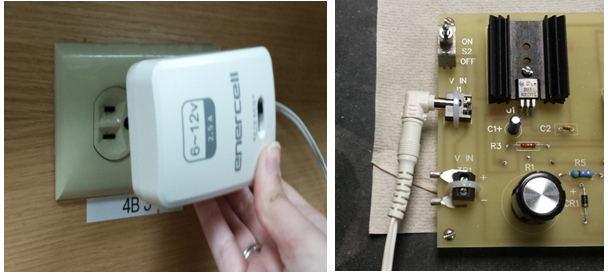 | STEP ONE: Connect the AC adapter to a power outlet and set it to 12V, then connect the other end to the electrostation. |
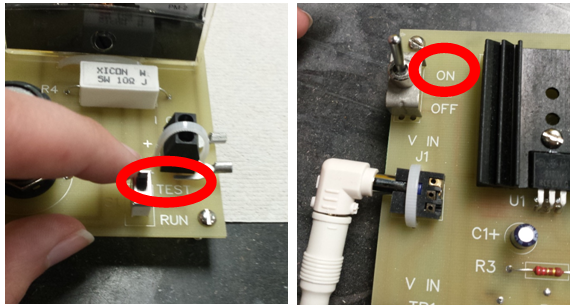 | STEP TWO: Switch the electrostation to the RUN mode, and flip the switch to ON. |
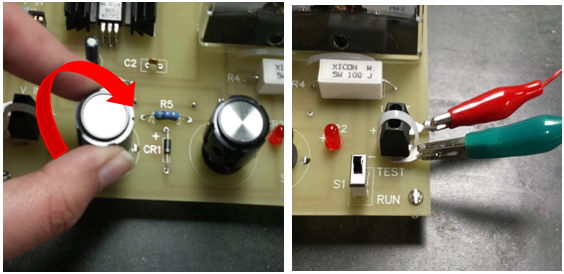 | STEP THREE: Ensure the two knobs on the electrostation are set to the maximum current by rotating them clockwise. Then, attach the alligator clips to the two output terminals by the TEST and RUN switch (on the right side). |
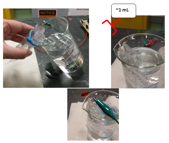 | STEP FOUR: Fill each electrode tube with the water + electrolyte solution. Then, very carefully, invert the tubes into the beaker. There should be a 1mL space of air at the tip of the tubes. Lastly, connect the alligator clips from the electrostation to the tubes, making sure that they do not touch. |
Appendix B. Pt|X Electrolysis Results
 | Figure A1. Electrolysis experiments for various metals (anode) with Pt cathode in acidic media |
 | Figure A2. Electrolysis experiments for various metals (cathode) with Pt anode in acidic media |
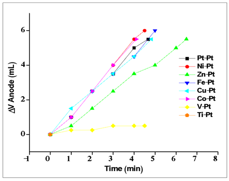 | Figure A3. Electrolysis experiments for various metals (anode) with Pt cathode in acidic media |
 | Figure A4. Electrolysis experiments for various metals (cathode) with Pt anode in basic media |
Appendix C. Voltammograms
 | Figure A5. Linear sweep voltammograms for the oxidative component of electrolysis under acidic conditions |
 | Figure A6. Linear sweep voltammograms for the oxidative component of electrolysis under basic conditions |
 | Figure A7. Linear sweep voltammograms for reduction under acidic conditions |
 | Figure A8. Linear sweep voltammograms for reduction under basic conditions |