-
Paper Information
- Previous Paper
- Paper Submission
-
Journal Information
- About This Journal
- Editorial Board
- Current Issue
- Archive
- Author Guidelines
- Contact Us
Journal of Laboratory Chemical Education
2015; 3(1): 7-11
doi:10.5923/j.jlce.20150301.02
An Inexpensive Homemade Polarimeter for Demonstration Use in the Classroom
 Abstract
 Reference
 Full-Text PDF
 Full-text HTML
Gary W. Breton
Department of Chemistry and Biochemistry, Berry College, Mount Berry, USA
Correspondence to: Gary W. Breton , Department of Chemistry and Biochemistry, Berry College, Mount Berry, USA.
| Email: |  |
Copyright © 2015 Scientific & Academic Publishing. All Rights Reserved.
We describe a simple homemade polarimeter that can be conveniently used in the classroom to demonstrate the application of polarized light towards the detection of chirality. The basic theory behind the operation of a polarimeter is discussed. Example data for (+)-α-pinene and (–)-β-pinene are included.
Keywords: Chirality, Polarimeter, Polarized light, Pinene, Classroom demonstration
Cite this paper: Gary W. Breton , An Inexpensive Homemade Polarimeter for Demonstration Use in the Classroom, Journal of Laboratory Chemical Education, Vol. 3 No. 1, 2015, pp. 7-11. doi: 10.5923/j.jlce.20150301.02.
Article Outline
1. Introduction
- Chirality is an important topic in any introductory Organic Chemistry course. Typically included in the discussion of chirality is the use of a polarimeter to determine the optical rotation of chiral compounds. Although the theory behind polarimeters is quite simple, we have found that undergraduate students often have a difficult time conceptualizing how the angle of rotation of polarized light is measured in practice. While commercial polarimeters can be purchased, they are expensive and not particularly conducive to being used to demonstrate their application for the detection of chirality in a classroom setting. Several homemade polarimetershave been reported in the literature [1], and some have been specifically designed for use in classroom demonstrations [2]. However, we found the designs for the reported classroom demonstration units to be either inconvenient for easy setup in the classroom, or much more involved than we thought necessary. We decided to design and construct our own polarimeter with the aim of making it simple to build, convenient to use in the classroom, and inexpensive.
2. Basic Theory of a Polarimeter
- The basis components of a polarimeter are two polarizing lenses capping a sample tube (A in Scheme 1). Incoming nonpolarized light (to the left of the sample tube in A) is polarized as it passes through the first polarizing lens and into the empty sample tube. The polarized light is unperturbed by the empty tube and emerges in the same plane in which it was originally polarized. Thus bright light is observed at the other end of the tube. In B, the polarized light is passed through the sample tube filled with an optically inactive substance (e.g., water). Optically inactive substances do not affect the plane of polarized light and it emerges from the polarimeterthe same as if the sample tube were empty. In C, however, the sample tube is filled with an optically active substance (i.e., a single enantiomer of a chiral molecule, or a scalemic mixture of enantiomers). In this case, the plane of polarized light is rotated as it passes through the sample tube. If one is viewing through the second lens, the light does not pass through the lens readily. Upon rotation of the lens (either in the dextrorotatory [i.e., +] or levoratorory [i.e., –]direction) the second lens eventually lines up with the plane of polarized light and maximum transmittance of light is again observed. The resulting angle of rotation is called the “observed rotation”. To convert the observed rotation to a standardized specific rotation, at the very minimum the length of the sample tube (in dm) and concentration of the sample (in g/mL) need to be taken into account (equation 1):
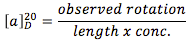 | (1) |
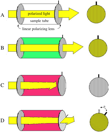 | Figure 1. Basic componentry and theory of a working polarimeter |
3. Construction of the Polarimeter
- The essential items needed for construction of the polarimeter are displayed in Figure 2. Two inexpensive pieces of linear polarizing film, a 100 mL beaker (5 x 7.5 cm, preferably without a pouring lip at the top), two pieces of 2” i.d. PVC pipe cut to length (the bottom piece at ~7 cm and the upper piece at ~1 cm using a standard miter saw), and aprotractor face printed out on suitable card stock. The sources for these items can be found in reference [3]. The 7 cm high “body” of the polarimeter is cut slightly shorter than the 7.5 cm beaker “sample tube” so that the sample tube can be conveniently added to or removed from the body without spilling the contents.
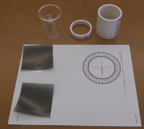 | Figure 2. Essential items required for construction of the polarimeter |
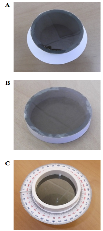
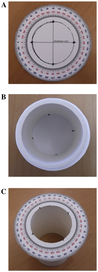 | Figure 3. (A) Centering the PVC body onto the face of the protractor; (B) Gluing the PVC body to the back of the protractor face; (C) PVC body with center of protractor face removed |
 | Figure 4. (A) Polarizing lens glued to bottom of PVC body; (B) Polarizing lens glued to top piece of PVC; (C) Pointer glued into the PVC body at a reading of 0° on the protractor |
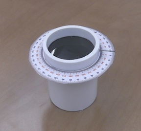 | Figure 5. Complete assembly of final polarimeter |
4. Operation of the Polarimeter
- When demonstrating the use of a polarimeter in class, the entire unit is placed on a light source (such as the base of a document camera or overhead projector) initially without the top polarizing lens or sample cell in place. The image is cast onto a suitable screen in the room. Students can readily see that the intensity of the light coming through the bottom polarizing lens is dimmed relative to the light not flowing through the lens. The top polarizing lens is then put in place and it is demonstrated that when the lens is in the 0° position, no polarized light is transmitted through the top lens, but if it is turned to 90°, all of the light is transmitted (Figure 6).
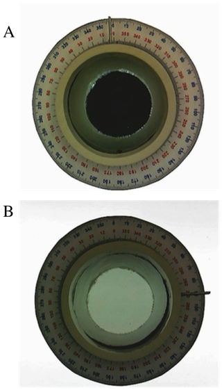 | Figure 6. Images viewing through the top of the polarimeter which is sitting on a light source. (A) Obvious absence of light transmittance when the dial indicator on the top polarimeter is set to 0° (i.e., the two linear polarizers are orthogonal); (B) Complete transmittance of light when the dial indicator on the top polarimeter is set to 90° (i.e., the two linear polarizers are collinear) |
 | Figure 7. Images similar to those in Figure 5 except the sample cell was filled with water |
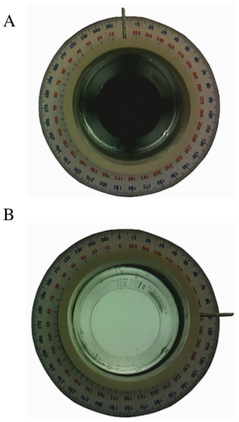
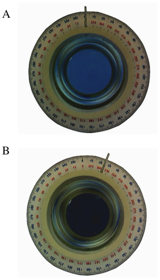 | Figure 8. Behavior of the polarimeter when the sample cell was filled with (+)-α-pinene. (A) When the indicator dial is left at a setting of 0°, obvious light transmittance through the top polarizer lens is observed. (B) Rotating the top polarizer lens to a setting of 25° minimizes the transmission of light and this value is taken as the observed rotation |
5. Conclusions
- An inexpensive, homemade polarimeter has been developed that provides an excellent means by which to illustrate the use of a polarimeter to measure specific rotations. (+)-α-pinene and (–)-β-pinene areconvenient compounds for analysis since they are of relative low cost and have pleasant odors (of course, all compounds should be handled in a safe manner!). Furthermore, they demonstrate the observation of levorotatory versus dextrorotatory rotations. Because of the rudimentary nature of the polarimeter, values obtained have a percent error on the order of 10%. Therefore, while not suitable for quantitative experimentation, use of this unit in classroom demonstrations clearly shows students in a lecture room setting the general manner by which optical rotation data are obtained.