-
Paper Information
- Next Paper
- Paper Submission
-
Journal Information
- About This Journal
- Editorial Board
- Current Issue
- Archive
- Author Guidelines
- Contact Us
Journal of Civil Engineering Research
p-ISSN: 2163-2316 e-ISSN: 2163-2340
2021; 11(2): 46-50
doi:10.5923/j.jce.20211102.02
Received: Sep. 8, 2021; Accepted: Oct. 14, 2021; Published: Oct. 30, 2021

Control of Scouring Under Marine Pipelines Using Horizontal or Vertical Plates
 Abstract
 Reference
 Full-Text PDF
 Full-text HTML
Saeid Maddah Kolur1, Fereshteh Kolahdouzan1, Gholamreza Azadi1, Vijay P. Singh2, Hossein Afzalimehr1
1Department of Civil Engineering, Iran University of Science and Technology, Tehran, Iran
2Department of Biological & Agricultural Engineering & Zachry Department of Civil and Environmental Engineering, Texas A&M Univ., College Station, Texas, USA
Correspondence to: Hossein Afzalimehr, Department of Civil Engineering, Iran University of Science and Technology, Tehran, Iran.
| Email: |  |
Copyright © 2021 The Author(s). Published by Scientific & Academic Publishing.
This work is licensed under the Creative Commons Attribution International License (CC BY).
http://creativecommons.org/licenses/by/4.0/

This study experimentally investigated the effect of connecting vertical plates and horizontal plates and their combinations to single and double pipes on scouring under pipes. Experiments were performed in a laboratory flume 13 m long, 0.4 6m wide, and 1 m deep. Results showed that attaching a 0.25D vertical plate under a single pipe prevented scouring under it. Further, in order to control scouring under pipes using a horizontal plate, regardless of the number of pipes and their distance from each other, the plate should extend 0.5D upstream and downstream of the pipes. A combination of horizontal and vertical plates under pipes showed that in cases where the length of the horizontal plate was not enough to prevent the formation and development of scour under the pipes, the addition of vertical plates on both sides of the horizontal plate can protect the pipes against scouring.
Keywords: Scour depth, Vertical plate, Horizontal plate, Combined plates, Single pipe, Double pipes
Cite this paper: Saeid Maddah Kolur, Fereshteh Kolahdouzan, Gholamreza Azadi, Vijay P. Singh, Hossein Afzalimehr, Control of Scouring Under Marine Pipelines Using Horizontal or Vertical Plates, Journal of Civil Engineering Research, Vol. 11 No. 2, 2021, pp. 46-50. doi: 10.5923/j.jce.20211102.02.
Article Outline
1. Introduction
- Submarine pipelines are important infrastructure and are vital for transporting water, natural gas, oil and petroleum products. Over the last few decades, various methods have been proposed and investigated to protect pipelines from scouring. Some designers of offshore pipelines prefer to bury the pipelines under the seabed In order to protect them (e.g., Zhu et al 2019). One of the advantages of this method is to protect the pipeline against lateral movements caused by currents and sea waves. This method also protects the pipeline from the possibility of collision of ship’s anchors. However, with the burial of the pipeline, the possibility of physical inspection of the pipeline is eliminated and some problems are created in its maintenance stages.Hulsbergen (1984) found that by attaching a rigid piece or longitudinal blade to the top of the pipe, the rate of self-burial of the pipe can be increased. Cheng and Chew (2003) stated that by connecting the plate, the pressure gradient between upstream and downstream of the pipe increases significantly. As a result, it increases the flow through the gap between the pipe and the seabed and increases the shear stress of the seabed and accelerates the rate of self-burial. Through laboratory studies, Yang et al. (2012) investigated the effect of the longitudinal blade with different sizes of pipe diameter, considering the longitudinal blade height, amplitude and wave frequency under regular and irregular waves and found acceleration of scouring and burying of pipes with longitudinal blades. Zhang et al. (2013) investigated the effect of impermeable plates with different lengths, one-side (upstream only) and two-side and reported that with increasing the length of the plate, the pressure gradient between the two sides of the pipe (in both cases of one-side and two-side plates) decreases and as a result, the piping also decreases. They also said that the performance of one-side and two-side plates were similar, however, the two-side plates were more useful than the one-side plates due to the ease of installation under the pipeline.Yang et al. (2014) investigated the effect of rubber plates under the pipes in uniform flow and stated that by inserting a rubber plate under the pipe, the pressure difference between two sides of the pipe significantly reduced and with a certain length of the plate, called the critical length, had zero scouring depth under the pipe. Mohammadi and Hakimzadeh (2015) performed laboratory and numerical studies to investigate the effect of longitudinal blades connected below the pipelines. They used blades of relative lengths
 05, 0.10, 0.15, 0.20, 0.25, 0.50.
  is length of vertical plate and D is pipe diameter. Their results showed that the connection of longitudinal blades with
 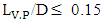 delayed the onset of scouring, but at the same time the maximum scouring depth increased significantly. On the other hand, by connecting the longitudinal blade with a relative length
  scouring did not occur under the pipe. Zhu et al. (2019) examined the self-burial trend of pipes with longitudinal blades used in the Hangzhou Bay of China from 2005 to 2016 and reported that during this period the amount of buried pipelines increased from 40% to 90%. Jabbari et al. (2020) also investigated the effect of longitudinal blades with relative lengths
  and unlike Mohammadi and Hakimzadeh (2015) found no scouring. Their results showed that the combination of this blade with the pipe had reduced the average length of the scouring hole under the pipe by 21% and increased its depth by 22%. Define the objectives of the study here.
2. Experimental Setup and Procedure
- For the experiments in this study, a flume with Plexiglas walls 13m long, 0.46m wide, and 1m deep was used, which had a centrifugal pump with a maximum power of 30 hp and a maximum capacity of 122 lit/s. In order to reduce the distance required to reach the fully developed flow condition, in the initial part of the flume, 1m long galvanized mesh sheets were placed on top of each other. The test section was located between 8.75 m and 10.25 m from the entrance of flume.For bed sediment, sand with a median particle size of
 =0.24 mm with standard deviation of less than 1.4 was used. In other parts, sand with a median size of
  =1.9 mm was used in which no sediment motion was observed. The height of bed material along the entire length of the flume was 20 cm. In all experiments, the flow was uniform and its average velocity was measured at a depth of 0.4 m from the bed and at a distance of 9 m from the entrance of the flume. A current-meter connected to a counter was used to measure the flow velocity. Experiments at each point were repeated at least 5 times and an average value was used. Melville and Sutherland relations (1988) were used to calculate the critical velocity (Equations 1 and 2). Flow velocity in all experiments was set at
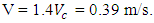
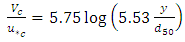 | (1) |
 | (2) |
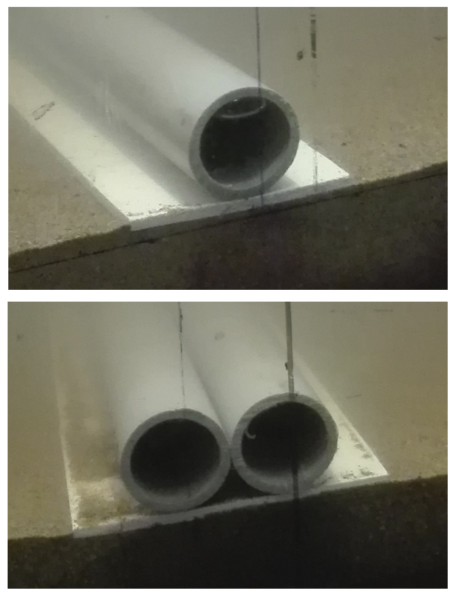 | Figure 1. Using impermeable plates under single and double pipes |
3. Results
3.1. Using a Vertical Plate under a Single pipe
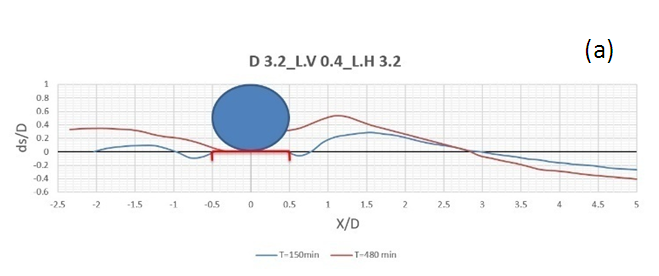
- In the first and second experiments of this section, a plate with a length of 0.125D = 0.4cm and 0.25D = 0.8cm were used, respectively. In the first experiment, compared to the single pipe test without plate insertion, the maximum scour depth increased by 27% and the time required for the test increased by 50%. In the second experiment, 480 min after the start of the experiment, no scour was formed under the pipe. The scour profiles of these two experiments are shown in Figure (2). Results of these experiments were consistent with the results of Mohammadi and Hakimzadeh (2015).
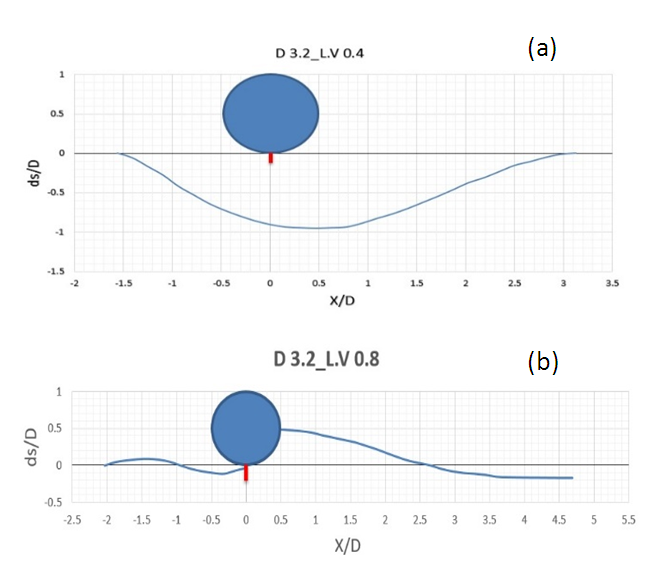 | Figure 2. Scour profile using a) 0.125D and b) 0.25D long vertical plates under single pipe |
3.2. Using Horizontal Plate under a Single Pipe
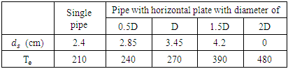
- In this section, 4 experiments were performed in which the plates with 0.5D = 1.6cm, D = 3.2cm, 1.5D = 4.8cm, 2D = 6.4cm long were placed under the pipe with a diameter of 3.2cm, respectively. Results of these 4 experiments are presented in Table (1).
|
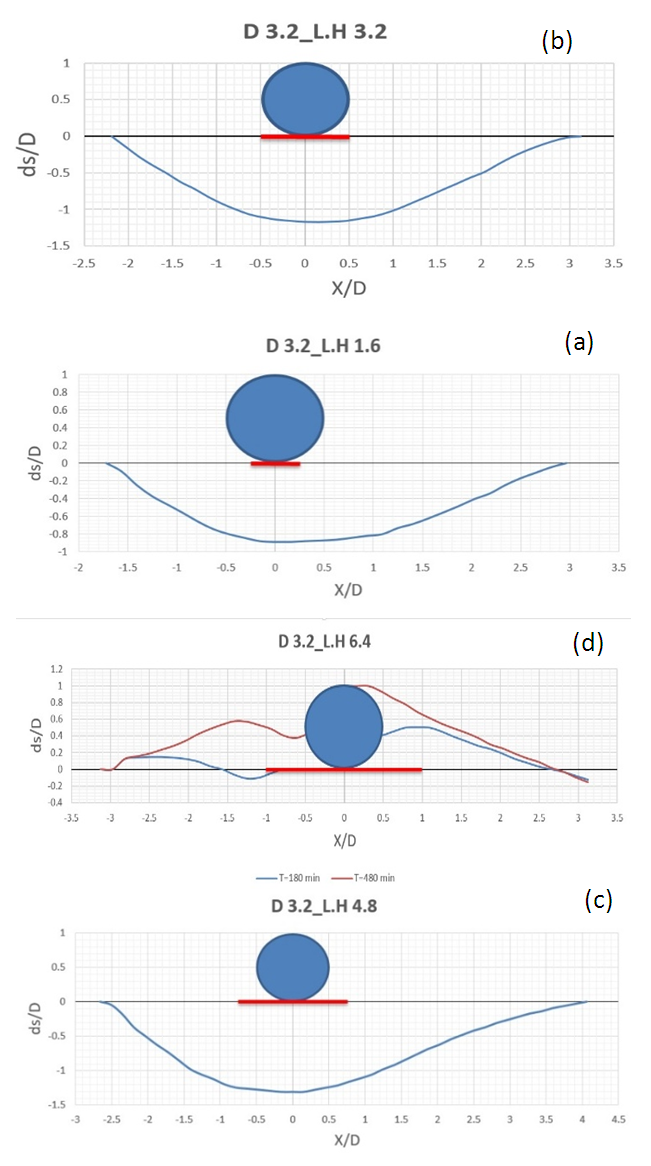 | Figure 3. Scour profile using a) 0.5D, b) D, c) 1.5D and d)2D long horizontal plates under single pipe |
3.3. Using Horizontal Plate under Two Pipes with No Distance (G=0)
- In the experiments of this part, first a 6.4 cm long plate was used under two pipes with a diameter of 3.2 cm. During 480 min, the scouring cavity did not form completely under the pipes (Figure 4 (a)), but the cavity formed in the upstream of the pipes was significant that at 260 minutes of the experiment, this cavity developed almost to the middle of the plate Located under the pipes. Therefore, the performance of this plate in terms of protection of pipes against scouring was unacceptable. In the next experiment, a 9.6 cm long plate was used, which protected the pipes well against scouring (Figure 4 (b)). Results of the experiments in this section showed that to protect the two pipes at G = 0 against scouring, a horizontal plate with a length of at least 3D below the pipes must be used. In this case, the plate was 0.5D long on each side of the pipes.
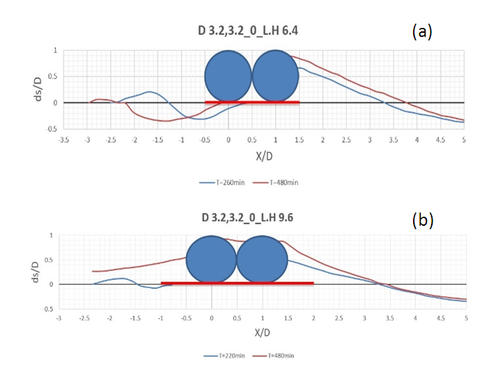 | Figure 4. Scour profile using horizontal plates with a) 6.4cm and b) 9.6cm long under double-pipe system with G=0 |
3.4. Using Horizontal Plate under Two Pipes with a Distance of G=0.5D
- In the experiments of this section, three plates with lengths of 3.2cm, 8cm and 11.2cm were used. In the first two experiments, although the scouring hole under the two pipes was not completely formed during 480min, but sediments under the upstream pipe were washed away. In the third experiment, the plate protected the two pipes against scouring for 480min. In this case, the length of the horizontal plate upstream and downstream of the pipes was 0.5D. Figure (5) shows the scour profiles in the experiments in this section.
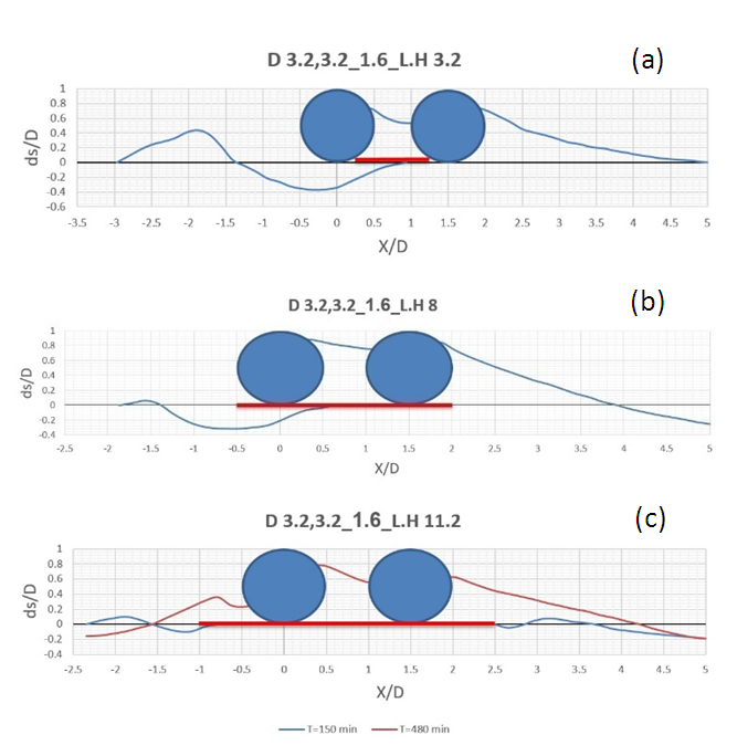 | Figure 5. Scour profile using horizontal plates with a) 3.2cm, b) 8cm and c) 11.2cm long under double-pipe system with G=0.5D |
3.5. Using a Combination of Horizontal and Vertical Plates under Pipes
- In the previous sections, it was observed that a vertical plate with a length of D/8 under a single pipe or a horizontal plate with a length of D under a single pipe could not protect the pipe against scouring. In the first experiment of this section, a combination of a vertical plate with length D/8 and a horizontal plate with length D under a single pipe was used. Figure (6) shows that in this case scouring was properly controlled. Also, in the experiment related to using 6.4 cm long horizontal plate under two pipes without distance from each other, it was observed that scouring occurred below the upstream pipe. In the second experiment in this section, vertical plates with a length of D/8 were connected to both sides of a horizontal plate with a length of 6.4 cm. Figure (7) shows that in this case the scouring was well controlled. According to experiments performed in this section, it can be concluded that in cases that the length of the horizontal plate is not enough to prevent the development of scouring under the pipes, adding vertical plates to both sides of the horizontal plate can protect pipes against scouring.
 | Figure 6. Scour profile using combination of horizontal and vertical plates under single pipe |
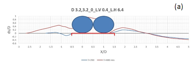 | Figure 7. Scour profile using combination of horizontal and vertical plates under double pipe |
4. Conclusions
- In the experiments of this study, horizontal and vertical plates and their combination under single and double pipes were used. The following is a summary of the most important results obtained from these experiments:1. Using 0.125D long vertical plate under the pipe caused a significant delay in the onset of scouring, but after the formation and development of scouring under the pipe, the maximum scour depth was 27% greater than the maximum scour depth under the single pipe. Also, using 0.25D long vertical plate under the pipe caused significant protection against scouring.2. In several experiments, horizontal plates of different lengths were placed under a single pipe and its effect on scouring was investigated. Finally, using a 2D long horizontal plate under the pipe resulted in proper scour control. Also, in double-pipe experiments, using 3D long horizontal plate under the pipes with G=0 and 3.5D long horizontal plate under the pipes with G=0.5D caused an acceptable reduction of scouring.Based on the results above, in order to properly control scouring under the pipes using a horizontal plate, regardless of the number of pipes and their distance from each other, the plate should extend 0.5D upstream and downstream of the pipes.3. Results of experiments performed using a combination of horizontal and vertical plates under the pipes showed that in cases that the length of the horizontal plate was not enough to prevent the formation and development of scour under the pipes, adding vertical plates to both sides of the horizontal plate can protect the pipes from scouring.For future studies more advanced protection methods against corrosion can be used to reduce the cost of river restoration projects.
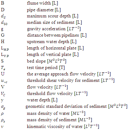
Notation
- The following symbols are used in this paper: