Zijad Ferhatbegović1, Agim Papraniku2
1The University of Tuzla, Faculty of Mining, Geology and Civil Engineering, Tuzla, Bosnia and Herzegovina
2ARTING BH d.o.o.Sarajevo, Bosnia and Herzegovina
Copyright © 2019 The Author(s). Published by Scientific & Academic Publishing.
This work is licensed under the Creative Commons Attribution International License (CC BY).
http://creativecommons.org/licenses/by/4.0/

Abstract
The paper analyzes the causes and mechanisms for sliding in the settlement Mahmutović, municipality of Sapna, that threatened three residential buildings. After the investigations carried out (four exploratory boreholes B-1 to B-4) and detailed engineering-geological mapping, a detailed engineering and geological map of the landslide was prepared. Based on the established properties of the landslide (size, volume, type of landslide), the causes and mechanisms of sliding, it was proposed measures of remediation landslide. After simulations on numerical models, using the PLAXIS 2D v8.5 software package, it is suggested to build a retaining wall on the counterfort, making of drainage systems in the form of fish bones and regulation of the roof water and fecal water in the appropriate receiver or drainage system.
Keywords:
Landslide, Sliding, Drainage system, Reinforced concrete wall on the counterfort
Cite this paper: Zijad Ferhatbegović, Agim Papraniku, Rehabilitation of Landslide in the Settlement Mahmutovići, the Municipality of Sapna, Journal of Civil Engineering Research, Vol. 9 No. 2, 2019, pp. 58-65. doi: 10.5923/j.jce.20190902.03.
1. Introduction
In 2014, during the heavy rains, in the settlement Mahmutovići, the municipality of Sapna, a landslide was activated that threatened three residential buildings. Due to slipping, plastic sewer pipes are broken, while the auxiliary dryer is destroyed and moved 40-50 meters from the original location. As a temporary measure of remediation under the houses, nylon is placed that prevents further soaking and sloughing of the soil. To stabilize the terrain, 20 wooden pilots were inserted into the ground. It has been observed that in one of the three buildings there are no gutters, so all the water flows over the surface of the terrain and contributes to the instability of the terrain.
2. Geomorphological, Hydrogeological, and Engineering Geological Characteristics
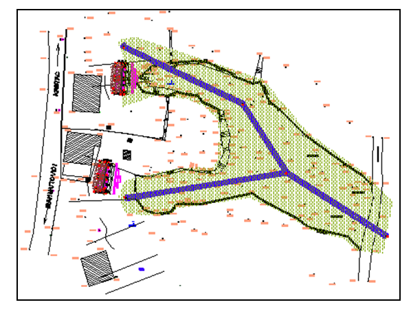
The landslide is located on the hillside with exposition towards the east. The inclination of the hillside is 19° and according to the inclination it is classified into a medium steep slope and according to the form in the concave hillside. Due to the presence of water, it is classified into a little sodden slope with occasional occurrences of diffusion filtering and wetting by groundwater in individual parts. Based on the geological map of Zvornik 1: 100 000 the subject site is located in the part of the terrain that builds the middle Miocene sediments (2M22) that represented by sandstones, clays, and marls. Dip azimuth of the sediments is towards the northeast at an angle of 200. Marls and sandstones take part in the substrate structure, while surface deposits built by multicolored sandy dusty clay to marly clay. Surface waters have not been observed in the investigated field. Near the landslide, two wells are registered: the well 1 northeast of the B-2 borehole at a distance of 30 meters and the well 2 southeasts of the borehole B-4 at a distance of 36.7 meters. In the first well whose depth of 3.0m, groundwater is registered at a depth of 30cm from the surface of the terrain while the other well was locked so the water level in this well not registered. The presence of the wells near the landslide indicates that the hillside is watered.To define the geological, engineering and geomechanical characteristics of the terrain, four exploration boreholes were performed. In exploratory boreholes, sandy-dusty to marly-clay, sand, sandstone, and marl were determined. Based on the performed experiments of standard dynamic penetration in boreholes, it has been proven that the compact soil occurs at depths of 1.8 to 3.0 meters. These depths represent the depths to the sliding surface. In the investigated terrain, the geological substrate is represented by a complex of rocks built of marls and fine-grained yellow-green sandstone. The mentioned rocks belong to a group of poorly-petrified rocks that, under the influence of exogenous forces, decompose and form thick clay-sandy blankets with debris. The substrate is at a depth of 1.8 to 3.0 meters. The surface coverings are eluvial-diluvial and colluvial. The eluvial-diluvial blanket was created as a consequence of the decomposition of the geological substrate and accumulation of disintegrated material from the higher parts of the slope to the central part of the slope. The lithological composition of this cover is represented by sandy-dusty to marl clay. The eluvial-diluvial blanket has a significant distribution on the subject area and builds stable rounded ridge forms. In hydrogeological terms, the eluvial-diluvial blanket has the role of hydrogeological conductors. The colluvium is distinguished by poor geotechnical characteristics and soft consistency due to the influence of surface (atmospheric) and filtering waters. In the lithological composition of this cover are tawny and gray sandy-dusty to marl clay with carbonate detritus.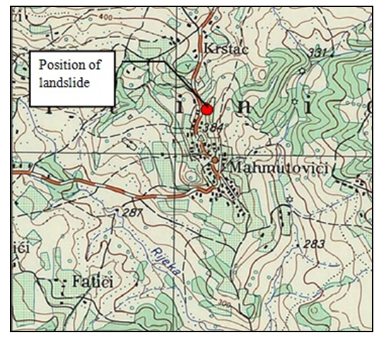 | Figure 1. The situation of landslide –topographic map Stari Teočak 1:25000 |
3. Description of the Landslide
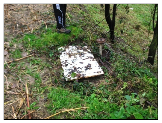
The landslide was created due to the slipping of a surface covering consisting of sandy-dusty and marl clay over the substrate represented by marl and sandstone. It is a shallow landslide, where the depth to the sliding surface is 3.0m.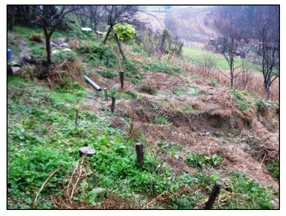 | Figure 2. Wooden piles |
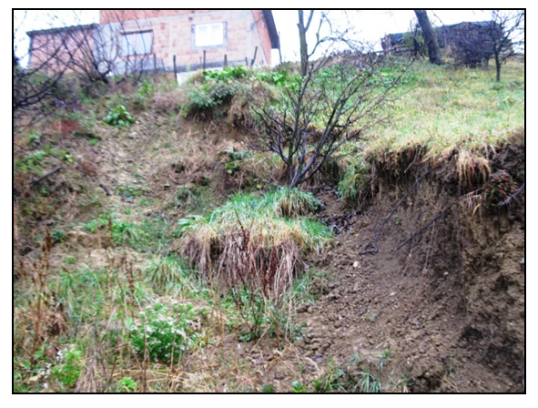 | Figure 3. Sliding body |
According to the material of the natural slope and the position of the sliding surface, this landslide is classified into consequent landslides (formed at the contact between the loose surface cover and the geological substrate). According to the position on the slope, it is classified into peak landslides located near the local water divide. The landslide is pear-shaped and, according to the surface and volume of the sliding body, it belongs to landslides of medium size. According to the site of the sliding process initiation, it is a detrusion landslide where the activation of the sliding process is performed in the hypsometric higher parts of the terrain (near the water divide) and the gradual slipping is successively moved towards the lower parts of the terrain.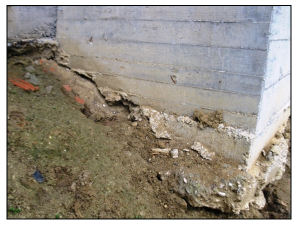 | Figure 4. The endangered foundation of the building |
The main causes of the slipping of the terrain:- excessive precipitation, - saturated slope,- the inclination of the slope,- lithological composition,- dissipating of roof water on the surface of the terrain.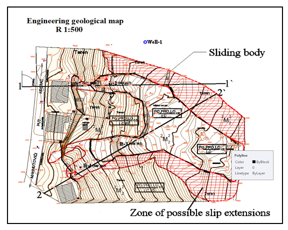 | Figure 5. Engineering geological map |
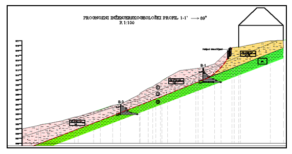 | Figure 6. Forecast engineering geological profile |
4. Slope Stability Analysis
Geostatic slope stability analysis was carried out using the boundary equilibrium method using the SLOPE / W option of the Geo-Slope International computer program. This program allows the stability of a budget according to various methods of marginal equilibrium: simplified Bishops, simplified Janboo, Spencers, Morgenstern-Price methods, etc. The program also provides the possibility of analyzing the stability of various types of sliding surfaces. In the stability analysis of the slope, the Morgenstern-Price calculation method was used, which satisfies both the balances (momentum and force), with simplified lamellar forces considerations. 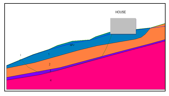 | Figure 7. The slope in the natural state |
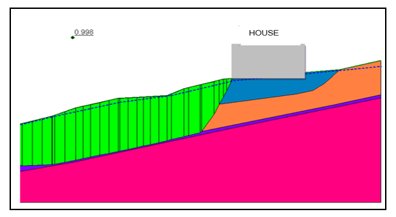 | Figure 8. Safety coefficient for sliding surface I-I, Fs = 0,998 |
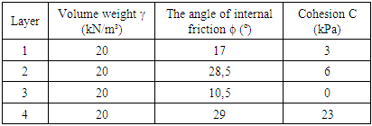
The analysis was done on a characteristic terrain profile. Analysis of the slope stability was made for the slope in the natural state and the slope after the implemented remediation measures.The calculated safety coefficient for the slope in the natural state is Fs = 0,998. This coefficient is unsatisfactory for the stability of the slope. Based on the safety coefficient it can conclude that this is an unstable slope. Based on the results of laboratory testing of soil samples, field observations, results of reverse analysis and experiences with similar materials, the following budgetary parameters that have been adopted showed in Table 1.Table 1. Tabular overview of soil parameters
 |
| |
|
5. Description of the Basic Concept of the Solution
 | Figure 9. Proposed remediation measures (retaining walls under houses and drainage system in the form of fish bones.) |
Based on the determined general properties of landslides such as (size, volume, type of landslide), causes and mechanisms of moving of earth, proposed remediation measures are consisted of: making of retaining structures on the counterforts, a drainage system in the form of fish bones for the collection and drainage of surface and groundwater and regulation of the roof water and fecal water in the appropriate receiver or drainage system.
5.1. Geostatic Analysis
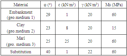
The numerical calculation of the stability and size of the retaining structure is carried out in the PLAXIS 2D v8.5 software package. The characteristics of previously adopted geotechnical environments forming the numerical model are given in Table 2.Table 2. Characteristics of Geotechnical Media Material
 |
| |
|
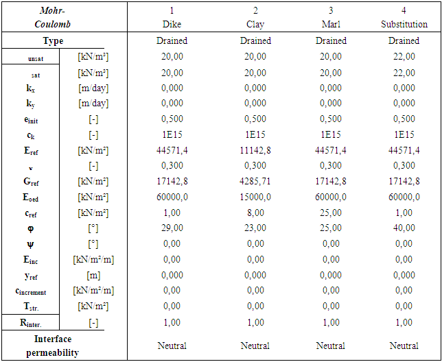
Considering that within the Engineering Geology and Geomechanical Survey it was done to check the stability and to determine the factors of the security of the existing state, in this paper is given only the calculation after the renovation by building a new retaining wall. The results of the numerical analysis are given below.Table 3. Soil characteristics
 |
| |
|
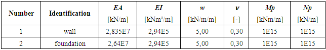
Table 4. Characteristics of the support structure
 |
| |
|
 | Figure 10. Calculation model of landslide |
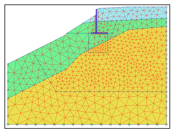 | Figure 11. Finite element network generated |
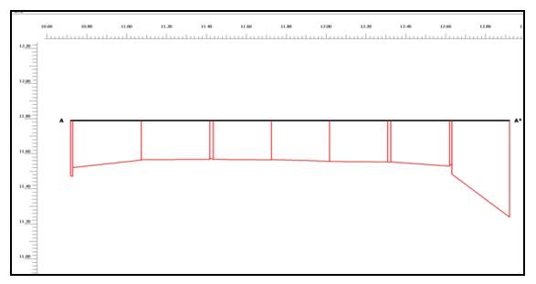
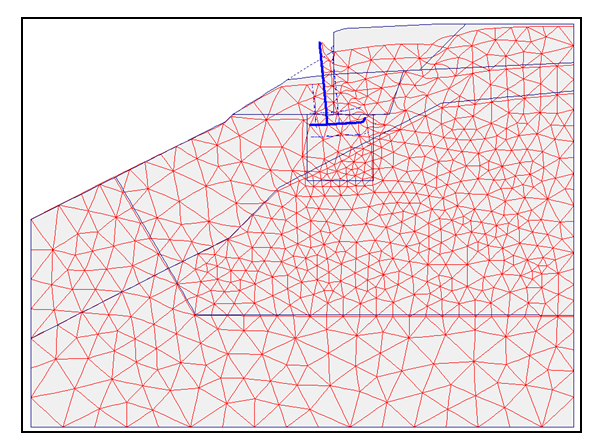 | Figure 12. The appearance of a deformed network of finite elements |
It was done a numerical model in Plaxis 2d v.8.5software package for the existing situation as well as for the proposed remedial solution. 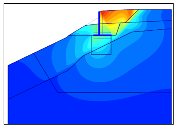 | Figure 13. An overview of total sinking after the construction of the retaining structure |
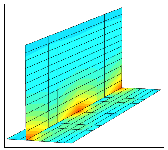
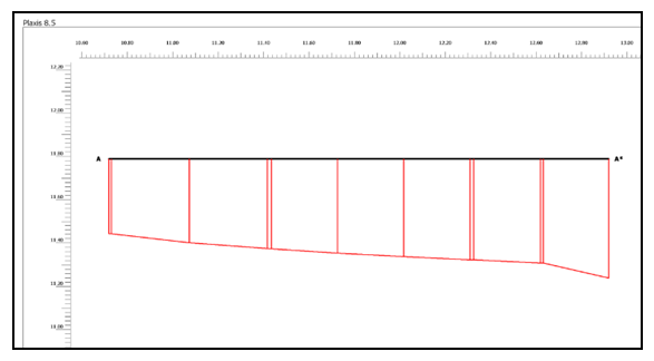 | Figure 14. The horizontal displacement of the structure (section below the foundation, Ux = 0.3 cm) |
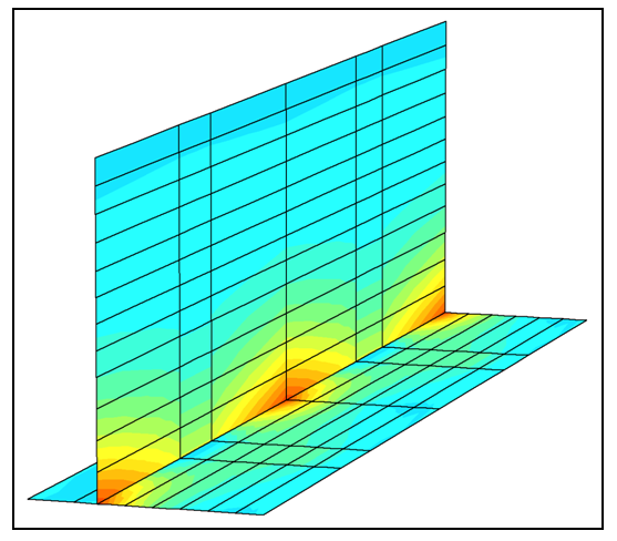
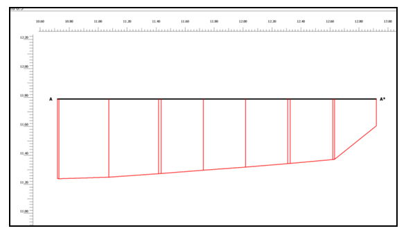 | Figure 15. Vertical displacement of the structure (section below the foundation, Uv = 0.4 cm) |
 | Figure 16. Diagram of the main effective stresses (pmax = 121.83 kN / m2) |
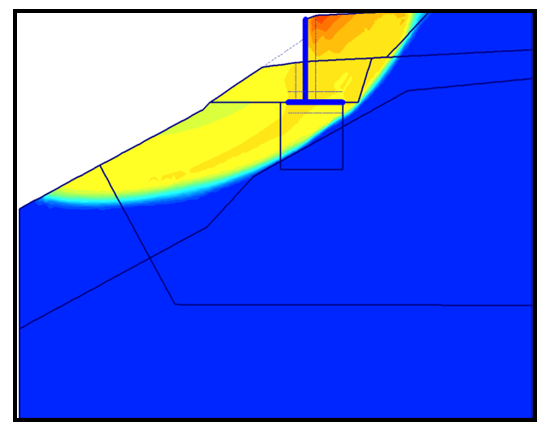 | Figure 17. Global stability check (Phi-c reduction, FS = 1.35) |
 | Figure 18. Bending moments in the wall M1-1 = 70 kNm / m |
 | Figure 19. Bending moments in the wall M1-1 = 90 kNm / m (Fs = 1.35) |
Conducted numerical simulation on models with facts and adopted assumptions conditioned the choice of the model of rehabilitation with retaining structure on the counterfort.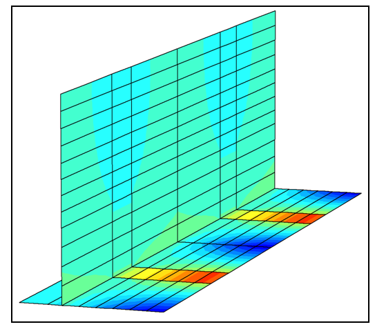 | Figure 20. Bending moments at a footing of M2.2 = 75 kN / m |
 | Figure 21. Bending moments at a footing of M2.2 = 92 kN / m (Fs = 1.35) |
Based on the obtained results, it can be concluded that the displacement of the construction is acceptable and that the safety factor after construction is satisfactory.In proof of static stability, EN 1997-1 (Eurocode 7: Geotechnical Design - Part 1) was applied. Several partial factors for the limit state of stability were used, at STR and GEO proof of bearing capacity.The adopted dimensions of the AB structure (wall and counterfort) at this stage are sufficient to transfer the load to the ground, as well as to the limitation of the slip size.
5.2. The Drainage System in the Form of Fish Bones
At the indicated location, no surface and groundwater were recorded in the exploratory boreholes. There are two wells in the landslide. In the first well whose depth of 3.0 m is registered water at a depth of 30 cm from the surface of the terrain, while in the second well, the water level was not registered because it was closed. According to the statement of locals, this second well with a depth of more than 6 meters is operational.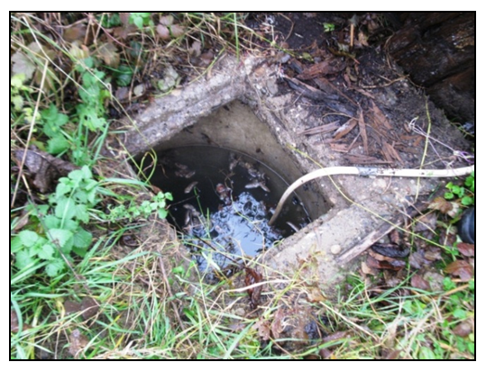 | Figure 22. The well 1 |
 | Figure 23. The well-2 (locked) |
The appearance of water in the wells indicates that the slope is partially watered and that for these reasons it is necessary to do the drainage system as proposed in the project. The drainage capacity has been estimated based on experience on similar landslides. It is planned to install perforated drainage pipes Φ300mm in the total length of 165,65 meters. The drainage pipes will be placed at a depth of 2-3 meters in the substrate. The goal of the drainage production is controlled acceptance and drainage of water from saturated soil.
5.3. Regulation of the Roof Water and Fecal Water
On the field, it has been observed that there are no gutters in some houses, and the water freely scatters over the surface of the terrain and saturates the soil. In this way, the stability of the slope and the stability of the objects on the slope is endangered. To regulate precipitation waters from the roof surfaces, the project of landslide rehabilitation foresees that all roof water from all three facilities will be collected and planned in the appropriate receiver or drainage system.The project provided a solution to the management of fecal water from all three facilities, bearing in mind that these waters could be freely scattered over the surface of the terrain, which could again destabilize the slope below the facilities.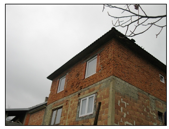 | Figure 24. House without gutters |
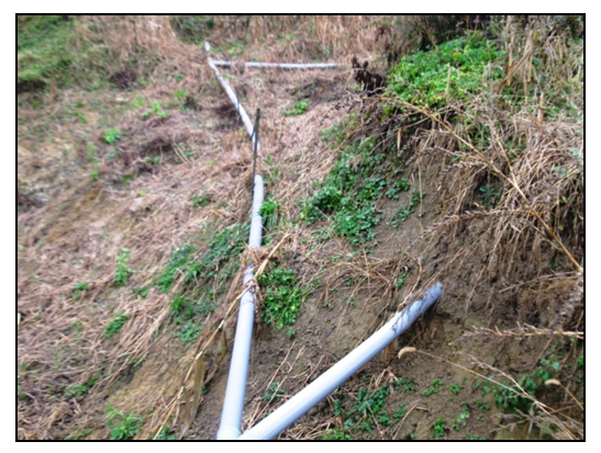 | Figure 25. Broken fecal pipes |
6. Conclusions
In the settlement Mahmutovići, the municipality of Sapna, a landslide was activated that threatened three residential buildings. After the investigations and detailed engineering-geological mapping, a study on geomechanical and engineering geological characteristics of the terrain was prepared, as well as the project of landslide rehabilitation. The main causes of the slipping of the terrain are excessive precipitation, saturated slope, the inclination of the slope, lithological composition and scattering of roof water on the surface of the terrain. Following the construction of the geotechnical profile analysis of the slope stability was made for the slope in the natural state and the slope after the implemented remediation measures. The analysis was performed according to the Morgenstern-Price method, and the obtained results are: the slope safety factor in the natural state is Fs = 0.998 and after the rehabilitation measures Fs = 1.35 (c reduction).The numerical calculation of the stability and size of the retaining structure is carried out in the PLAXIS 2D v8.5 software package.The proposed remediation measures consist of the construction of retaining structures on counterforts, drainage systems in the form of fish bones for the collection and drainage of surface and groundwater and regulation of the roof water and fecal water in the appropriate receiver or drainage system.The effectiveness of the proposed measures is reflected in the following:The retaining wall on the counterfort will protect the collapse of three residential buildings.Drainage systems in the form of fish bones will allow the draining of slope which will increase the stability of the slope.The regulation of roof water and fecal water will hinder saturating of the soil and impairing its stability.The proposed measures will significantly increase the stability of the slope and houses on the slope.
References
| [1] | Redžepović R., Ferhatbegović Z., “Kako živjeti na klizištu“, Specijalno izdanje Zavoda za geologiju, Sarajevo, 2001. |
| [2] | Redžepović R., Ferhatbegović Z., “Kako živjeti na klizištu“, Specijalno izdanje Zavoda za geologiju, Sarajevo, 2001. |
| [3] | Čačković I., “Stabilnost kosina i potporne konstrukcije“, Univerzitet u Tuzli, , 1-401, Tuzla, 2005. |
| [4] | Vrabac S., Pašić-Škripić D., Ferhatbegović Z., “Geologija za građevinare“, Univerzitet u Tuzli, 1-222, Tuzla, 2005. |
| [5] | Suljić N., 2010: “Potporne konstrukcije“, Univerzitet u Tuzli, 1-246, Tuzla, 2010. |
| [6] | Ferhatbegović Z., “Elaborat o geomehaničkim ispitivanjima tla za sanaciju klizišta u Mahmutovićima-općina Sapna“, 2015. |

 Abstract
 Reference
 Full-Text PDF
 Full-text HTML