A. B. M. Golam Rabbany1, Md. Hasan-Uz-Zaman2, Samiul Islam3
1Civil Engineering Department, Tung Hing (BD) MFY Ltd, Comilla, Bangladesh
2Engineering Department, Northern Techno Trade, Dhaka, Bangladesh
3Structural Engineering Department, Hifab International AB, Dhaka, Bangladesh
Correspondence to: A. B. M. Golam Rabbany, Civil Engineering Department, Tung Hing (BD) MFY Ltd, Comilla, Bangladesh.
| Email: |  |
Copyright © 2019 The Author(s). Published by Scientific & Academic Publishing.
This work is licensed under the Creative Commons Attribution International License (CC BY).
http://creativecommons.org/licenses/by/4.0/

Abstract
Most of the RCC columns are designed as short columns in practice. With the advancement of structural engineering concept and availability of high strength materials now it is increasing to apply slender column in some situations. Unlike short column, slender column design procedure requires so many criteria to reach a final design. In this study the behavior of slender column was studied. Different factors related to slender column performances are discussed here. This study will help the designer to predict the slender column performances in different situations. This study covers the discussion of sway frame, non-sway frame, P-Delta effect, story drift & displacement, earthquake load and some other necessary parameters as a whole. Some important comparisons also studied at the end.
Keywords:
RCC column, Slender column, Slenderness ratio, Sway & non sway frame, P- Delta analysis
Cite this paper: A. B. M. Golam Rabbany, Md. Hasan-Uz-Zaman, Samiul Islam, Performance of RCC Slender Columns in Different Conditions with Variations in Slenderness and Steel Ratio, Journal of Civil Engineering Research, Vol. 9 No. 1, 2019, pp. 25-42. doi: 10.5923/j.jce.20190901.03.
1. Introduction
Column is the main part of a structure. A beam failure would normally affect only a local region, whereas a column failure could result in the collapse of the entire structure. [1] RCC slender column design procedure is different as that of short column. Short column strength governs by material strength and section properties. Slender column strength governs by many factors and need some special measures such as more reinforcement and bracing element to increase its performance. It’s necessary for a structural engineer to know clearly about the internal changes in different parts of slender column.In this study one critical slender column will be designed considering all related parameters like stiffness, steel ratio, slenderness ratio, sway / non sway case etc. After that some comparisons will be done which will be helpful for structural engineers to decide where and when slender columns needed to apply efficiently and elaborate the slender column concept as a whole.
2. Some Terms Relating to Slender Column & Slenderness Effects
2.1. Introduction to Slender Column
Some guidelines are to be studied before proceeding for the calculation of column capacity. First order analysis is a method of structural analysis that doesn't consider the deformed shape of the structure. So the structural analysis carried through the common methods like moment distribution, slope deflection or stiffness methods are all first order methods since they don't iterate the calculations on the deformed shape again and again till convergence. But analysis with p-delta effect goes through the deformed shape of the structure and hence they are called second order analysis. Second order analysis is carried out for the whole frame not for a particular column only. Another important aspect for slender column design is that effective length is preferred in the calculation (not unsupported length) [2]. Column sizes are selected based on experience. Column of upper story carries less axial load but larger moments and vice versa for the columns in lower story. The load criteria of any member (Column or beam) are dominated by the material property and member dimension. Buckling effect significantly reduces the carrying capacity of the material in slender column. For these reason, long column requires more reinforcement ratio than that of short column if section dimension is restricted for aesthetic or architectural purposes.The above discussion is limited to vertical column only.Sometimes it needs to provide the column (Short & Long) in inclined position for some reasons. (E.g. the column to column distance gives some extra spaces to meet building facility requirement). Strut & tie model can be used to calculate the force and moment of inclined column [3].Many factors need to consider in case of inclined column design which will be discussed in another study.
2.2. Critical Load for Slender Column
The basic behavior of straight, concentrically loaded simply supported slender columns was developed by Euler in generalized form [4]; a member will fail by buckling at the critical load Pc=π2EtI/(kl)2. It is seen that buckling load decreases rapidly with the increasing slenderness ratio. This formula is valid for long column only.
2.3. ACI Criteria for Slenderness Effects in Columns
For compression members braced against side sway (In non-sway structures) the effects of slenderness may be neglected when klu/r<= 34-12 (M1/M2), otherwise slenderness effect must be considered [5].For compression members not braced against side way (In sway structures) the effects of slenderness may be neglected when klu/r<= 22, otherwise slenderness effect must be considered.Sway and non-sway frame is shown in the following Figure 1. 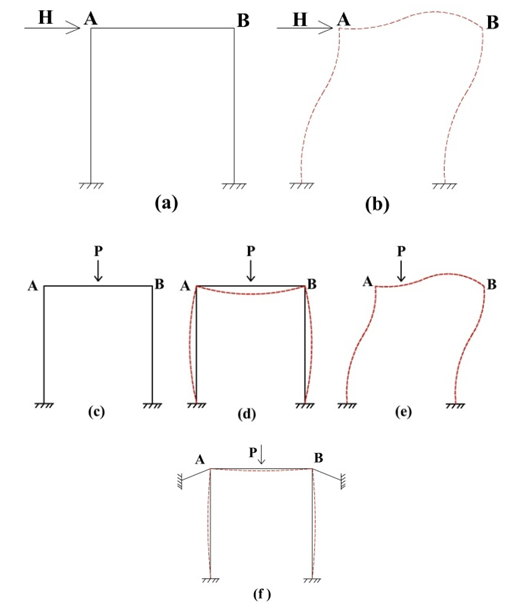 | Figure 1. (a) & (b) Sway frame due to horizontal force [6]; (c), (d) & (e) sway due to vertical force without bracing; (f) Frame with bracing (Negligible sway) |
2.4. Criteria of Slender Column
A column is considered to be a slender if its cross sectional dimension is small compared to its length. The moment and axial load obtained from first order analysis is sufficient to design short column. The secondary moment/lateral deflection is very low which can be neglected.In case of slender column there is a secondary moment caused by some transverse load / force (Wind or Earthquake force) simultaneously with the as usual load P or primary moment. The value of this secondary moment is quite high in slender column and needs to consider during design calculation. This phenomenon is called as P-∆ effect and elaborated in the below figure 2.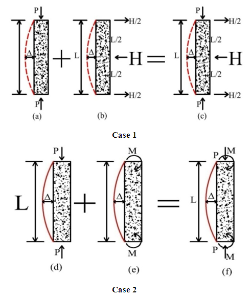 | Figure 2. P-∆ concept |
Form Figure 2 it is seen that ∆ = column / member deflectionIn Figure (a) the value of ∆ is negligible for the applied P only.In Figure (b) the member experienced a horizontal thrust / force which causes a significant value of deflection ∆.In Figure (c) the combination of the two cases (a) + (b) is called P-∆ effect.The final stage of Case 1 & Case 2 is same. In portal frame analysis the shear is calculated from moment divided by the arm. And sometimes moment is calculated by multiplying the shear with the arm. Same phenomenon can be applied in P-∆ effect. Because the value of ∆ is for horizontal force H associated with end moments or Vice versa. The deflection is proportional to the length of the column. The deflection and related additional secondary moment is significant and must be considered in design work. For this reason the P-∆ effect is a matter of study in long height column. The more the height of the column the more the deflection and less the safe value of P. Member of higher slenderness will collapse under a smaller compression load than a stocky member with the same cross sectional dimension [7]. In summary, a coefficient is needed which is multiplied by the moment which is obtained from normal procedure / first order analysis. In the next step calculation of this coefficient will be discussed.
3. RCC Slender Column Design Steps
3.1. Non Sway Frame
1. Perform First order analysis by using a standard software to obtain the axial load and moment of the column to be designed 2. Confirm if Non Sway frame. If sway frame then proceed with section 3.2 otherwise 3.1.3. Calculate unsupported length of column4. Check whether the column is short or long using the thumb rule. If the ratio of the unsupported length to the least lateral dimension of column section is more than or equal to 12 then we need to further proceed for actual calculation for slenderness effect.5. Calculate the slenderness from the formula K lu / rWhere K=Effective length factor lu= Unsupported lengthr = Radius of gyration (0.3 h for rectangular section)6. Calculate the value from, 34-12(M1/M2)Where M1=Numerically Lower moment & M2= Numerically Higher moment of the column to be designed 7. Compare the value of (5) & (6)The maximum value of (6) is taken as 40If the value of (5) is less than (6) then slenderness need not to be considered. That column can be designed as short column. Otherwise more refined value of K should be calculated using the next step.8. For bottom or ground floor rotational restraint factor is taken as 1.09. For other location, rotational restraint factor will be calculated as per section 4.4 using the combined stiffness of the beam column junction.10. Again check step (7) if not satisfy then proceed to step (11)11. Calculate the minimum moment from the equation M2,min= Pu(0.6+0.03h)12. Compare this value with the analysis value and take the governing one13. Calculate the equivalent uniform moment factor Cm (Cm=0.6+0.4(M1/M2)14. Calculate βdns (Ratio of maximum factored axial sustained load to maximum factored axial load associated with same load combination, but not greater than 1.0)15. Calculate EI EI = (0.4*Ec*I)/ (1+ βdns)Ec=Modulus of elasticity of concreteI = Moment of inertia of member16. Calculate critical load Pc = π2 EI/(Klu)217. Moment magnification factor,δ= Cm/(1-(Pu/0.75Pc))18. Using the revised moment check the steel ratio of that column section19. To check the moment capacity and load carrying capacity 20. If reinforcement ratio is more than 0.04 then column section should be changed. (For details discussion about the 0.04 limit see reference [1])
3.2. Sway Frame
Steps need to be considered… 1. Confirm if Sway frame. If non sway frame then proceed with section 3.12. Calculate the slenderness from the formula K lu / r3. As per ACI code slenderness effect may be neglected if K lu / r is less than 22. Calculation procedure of slenderness was described in details in Appendix B Table B01-B05 4. Calculate the seismic load (W) of the whole building as per Appendix C5. Calculate the fundamental time period for building T=0.075h0.75h=height of structure in meter6. Calculate floor wise seismic load and floor wise shear as per Appendix CCalculate base shear, Vb=AhWAh=ZIC/R Where, Z= Zone factor = 0.15R= Response modification coefficient=8 (Structure without shear wall)Vb=AhWI=building importance factorC=Numerical Coefficient Using different load combinations take the maximum displacement of the building with the help of any standard software.7. Calculate the stability indices of the building from the formula, Q=Pu /(∆u)/(Hu hs)Where Pu = Sum of axial loads on all columns in the ith story∆u = Elastically computed first order lateral deflection Hs = Total lateral forces acting within the storyhs = height of the storyIf the value of Q is equal to or less than 0.04 then the respective story is non-sway. Otherwise the story is sway. 8. If sway frame is confirmed then moment magnification can be calculated as δ = 1/ (1-Q). The moment magnification factor is also calculated as the step 15, 16 & 17 in section 3.1 but for large structure there is a possibility of error to calculation of critical load for different columns. Then proceed as step 18-20 in the section 3.1.
4. Application of This Study
4.1. Example Building Description
In the Figure 3 there are three isolated buildings forms a combined industrial building leaving a small gap with each other.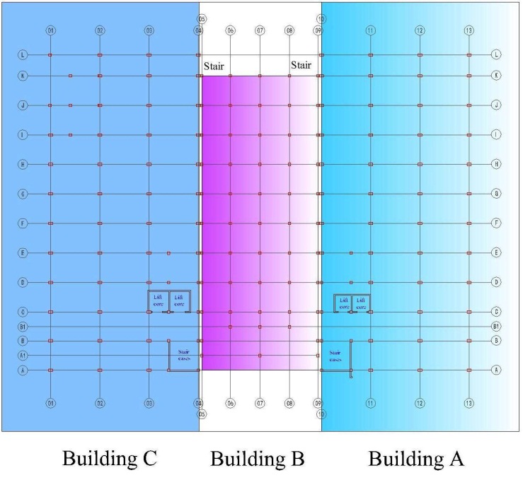 | Figure 3. Example building layout plan |
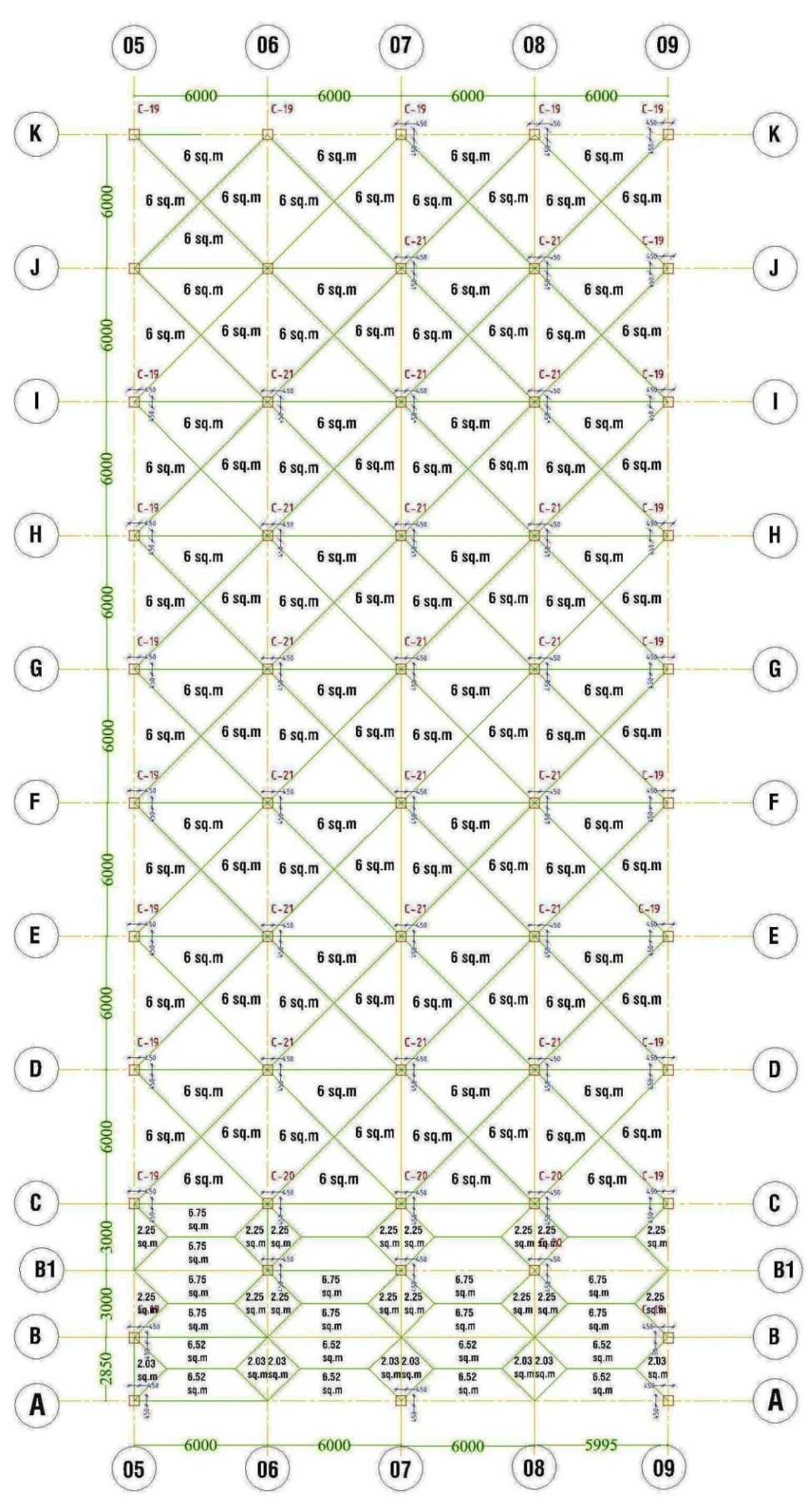
This study analyzed the middle part only. There is a loading unloading area in front of the middle building where long height cargo container will move. This middle portion of the building used as warehouse and for client requirement around 5.5 m clear height is mandatory. So there is a possibility to consider the ground floor column as slender column.Initially the middle portions (B building) have 55 columns. For the convenience of loading unloading work the red marking columns (Shown in Figure 4) may be avoided and A-07 grid column should be strengthen to carry extra loads for the removal of that two red marking columns.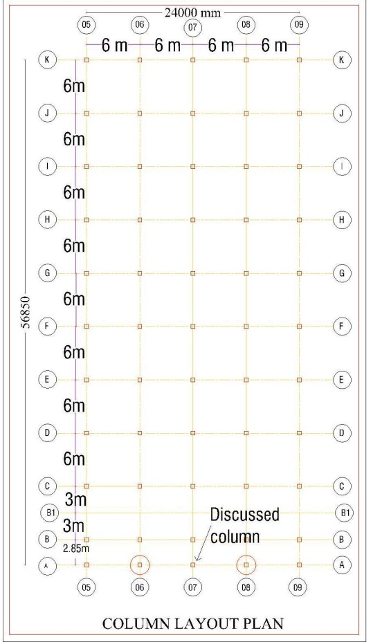 | Figure 4. Building B Column Layout Plan |
The Building size = 24 m X 56.85 mThe last digit of beam name denotes the beam length in mSlab width= 6+6+6+6=24 m Slab Length = (8*6) +3+3+2.85 = 56.85 mHere the column in A-07 grid line will be studied only.Column height=6 m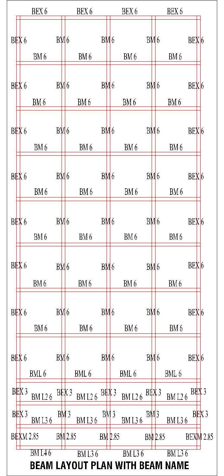 | Figure 5. Building B Beam Layout Plan with beam name |
4.2. Material & Section Properties of the Building
Concrete compressive strength, f’c= 30 MPa for columnand f’c= 25 MPa for other elementsfy = 415 MPaColumn Section, = 0.45 m X 0.45 mColumn Section below GL, = 0.525 m X 0.525 mMain Beam = 0.30 m X 0.60 mGrade Beam = 0.375 m X 0.675 mSlab Thickness, = 0.10 m0.230 m thick brick wall only in the peripheryNo brick wall inside.Terrace parapet height = 1.0 mLive Load (Typical floor) =7.0 KN/m2Live Load (Terrace) =1.5 KN/m2Floor Finish =1.0 KN/m2Water Proofing =2.0 KN/m2
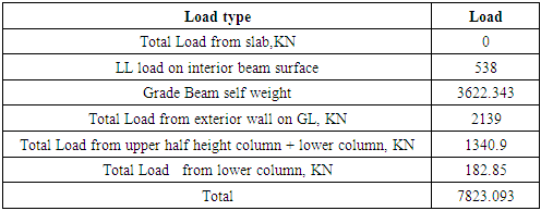
4.3. Unit Load Calculations
Concrete unit weight = 25.0 KN/m3 Brick wall unit weight = 19.0 KN/m3 Plaster work unit weight = 20.0 KN/m3 Columns (0.45 m X 0.45 m) = 5.06 KN/mColumns (0.525 m X 0.525 m) = 6.90 KN/mMain Beam (0.30 m X 0.60 m) = 4.50 KN/mGrade Beam (0.375 m X 0.675 m) = 6.33 KN/mSlab (0.150 m) =3.75 KN/m2 Brick wall (0.230 m) =4.90 KN/m2Brick wall (0.125 m) =3.30 KN/m2Beam weight per unit length (3.38 KN/m) after deduction of the slab thickness from beam depth.Parapet weight per unit length (4.9 KN/m). Parapet wall is only in the length of 24 m long in two sides only. Another two sides have two buildings and no need to consider parapet wall.Wall thickness = 0.23 m. All brick wall with both side 0.012 m thickness plaster.Parapet wall Load=24*2*4.9=235.2 KN
4.4. Effective Length Factor (K) Calculation
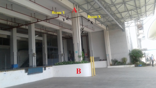 | Figure 6. The column discussed in this study (AB) |
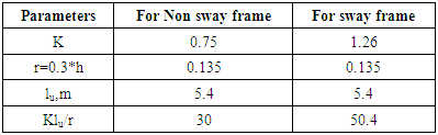
The stiffness of the top and bottom of the column should be calculated at first to find the effective length factor. In beam column joint; the beam may extend to one or both side of the joint. The stiffness at both sides of X-axis and Y-axis needs to be calculated. The stiffness of base is assumed as 1.0 [7]. After that the value of k is calculated from Graph A.8 in Appendix A depending on sway or non-sway frames.ψA(X) = Rotational Restraint Factor at point A in X directionψA(Y) = Rotational Restraint Factor at point A in Y directionψB= Rotational Restraint Factor at point B = 1The details calculation of K and rotational restraint factor of the column AB is shown in Appendix B.In this study the effective length factor K= 0.75 & 1.26 and the slenderness ratio is 30 & 50.4 for non-sway and sway frame respectively. The value of 34-12(M1/M2) is more than 40. (Using the analysis results in section 4.9).From previous table 01 the value of Klu/r confirms that the column must be considered as a slender column and need to follow the steps in section 3.2.Table 1. Slenderness ratio (Klu/r) calculation
 |
| |
|
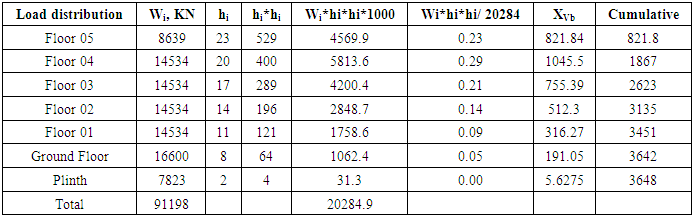
4.5. Building Seismic Weight Calculation
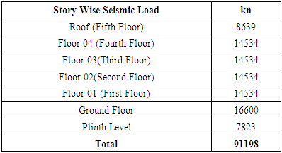
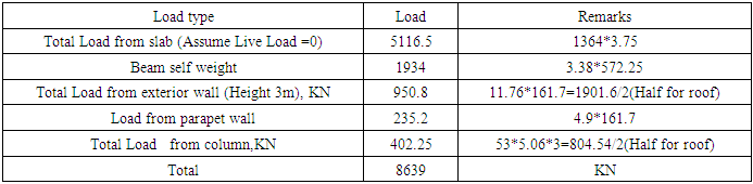
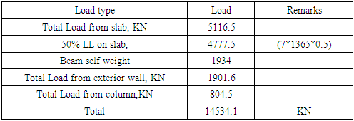
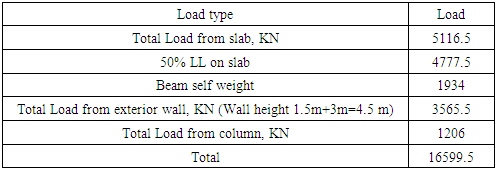
In this study the seismic weight of the entire building is considered as the summation of dead load and 50% live load [8]. The summary is shown in Table 2 (The detail calculation is shown in Table C01 to Table C06 in Appendix C).Table 2. Story Wise Seismic Load
 |
| |
|
4.6. Base Shear Calculation
Zone factor, Z=0.15 (Engineers should follow the code depend on locality)Building Height, hn = 23.0 mCt=0.073 for RCC moment resisting frame Fundamental time period, T = Ct (hn) ¾ =0.77Numerical co efficient C = 1.25 S / (T2/3) = 2.23S= Site coefficient for soil characteristics=1.5I =Building Importance Factor = 1.0W= Building/structure weight (DL+0.5LL)R=Reduction Factor =8.0Base shear, V = ZICW/RA= ZIC/R=0.04V=0.04*W=0.04*91198=3648 KN
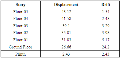
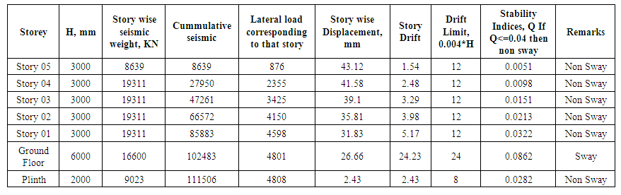
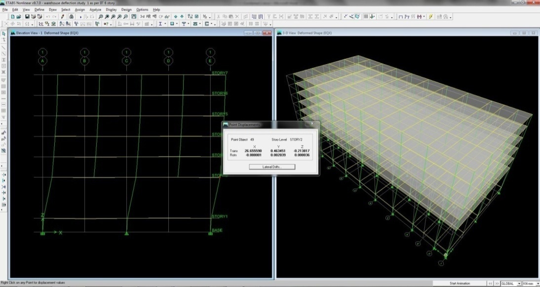
4.7. Story Displacement & Story Drift for Column Section 0.450 m X 0.450 m
From trial the below table is the maximum displacement for the load combination 1.2DL+0.5LL+ 1.2 EQX.From code it is stated that the maximum drift of a story for un factored lateral load is 0.004*Height of the structure.From software analysis the displacement of plinth level is 2.43mm and the ground floor is 26.66mm. That means the drift is 24.33mm. The maximum limit is 0.004*6000= 24 mm and thus satisfy the criteria.The drift of the story is quite a bit. It’s not a problem because we calculate the moment magnification coefficient for the load combination factored lateral load .In this case EQX causes maximum drift/displacement.Table 3. Displacement & drift for EQX (Unfactored) in mm
 |
| |
|
The story displacement value obtained from standard software is shown in Figure D01, D02 in Appendix D. If the EQX is multiplied with factor 1.2 then the drift will be 1.2EQX=24.23*1.2=29.04 mm.
4.8. Moment Magnification Factor
From Table C07 in Appendix CThe stability indices Q=0.0862 & 0.103 for story drift 24.2 mm & 29.04 mm respectivelyForm the step 8 in section 3.2 the value of moment magnification factor δ = 1/ (1-Q) =1.11 for Q = 0.103This factor will be multiplied by sway moment only which will be discussed in the next section.
4.9. Analysis Result
First order elastic analysis for A-07 gridline is done using standard software (ETABS) for load combination=1.2DL+ 0.5LL +1.2EQX
4.9.1. Case 1
(Section 0.45 m X 0.45 m) consider it as a short column.Axial load, Pu = 3392 KNM2= 297 KN, M1= -233 KNM1/M2= -0.78Kn= (Pu)/ (0.65*30000*0.2) =0.87Rn=(Mu)/ ( 0.65*30000*0.20*0.45)=0.17Gama, ɤ=0.72Using the value of Kn & Rn, steel ratio is obtained from Graph A.6 in Appendix A, ρ=0.0410
4.9.2. Case 2
(Section 0.45 m X 0.45 m) consider it as a long columnIn this case earthquake load is responsible for sway effect and the moment magnification factor will be multiplied only with the sway moment. Taking the moment magnification factor 1.11 from Section 4.8.The modified load combination will be now;1.2DL+ 0.5LL +(1.2*1.11)EQX.=1.2DL+ 0.5LL + 1.33 EQX.The multiplying factor 1.2 is replaced with 1.33 in case of EQX and put these changes in the load combination part of the software for getting the magnifying sway moment.Axial load, Pu = 3392 KNM2=329, M1= -258M1/M2= -0.78Kn= (Pu)/ (0.65*30000*0.2) =0.87Rn=(Mu) / ( 0.65*30000*0.2*0.45)=0.19Gama=0.72Steel ratio, ρ=0.0480
4.9.3. Case 3
(Section 0.50 mX0.50 m) consider it as a short columnAxial load, Pu = 3448 KNM2= 388, M1= -305M1/M2= -0.79Gama=0.75Kn= (Pu)/ (0.65*30000*0.25) =0.7Rn=(Mu)/ (0.65*30000*0.25*0.5)=0.16(Consider Graph A.6 & A.7 and taking the average)Steel ratio, ρ=0.0270
4.9.4. Case 4
(Section 0.50 mX0.50 m) consider it as a slender columnAxial load, Pu = 3448 KNM2= 430, M1= -338M1/M2= -0.79Gama=0.75Kn= (Pu)/ (0.65*30000*0.25) =0.7Rn=(Mu)/ ( 0.65*30000*0.25*0.5)=0.18Average Steel ratio, ρ=0.0327
4.9.5. Case 5
(Section 0.550 mX0.550 m) consider it as a short columnAxial load, Pu = 3495 KNM2= 477, M1= -375M1/M2= -0.79Gama=0.77Kn= (Pu)/ (0.65*30000*0.3) =0.6Rn=(Mu)/ ( 0.65*30000*0.3*0.55)=0.15Steel ratio, ρ=0.0180
4.9.6. Case 6
(Section 0.55 mX0.55 m) consider it as a slender columnAxial load, Pu = 3495 KNGama=0.77M2= 529, M1= -416M1/M2= -0.79Kn= (Pu)/ (0.65*30000*0.3) =0.6Rn=(Mu)/ ( 0.65*30000*0.3*0.55)=0.16Steel ratio, ρ=0.0215
5. Comparison Study & Result Analysis
5.1. Comparison 1
Steel ratio decreases with the increase of column section. This changing pattern is shown in the below Figure 7.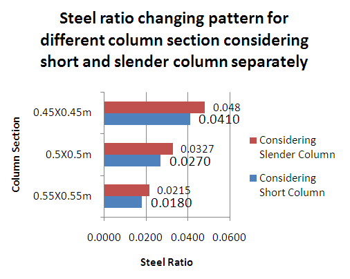 | Figure 7. Steel ratio changing pattern for different column section considering short and slender column separately |
5.2. Comparison 2
Slenderness ratio increases with the increase of the unsupported length of column. This changing pattern is shown in the below Figure 8.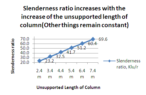 | Figure 8. Slenderness ratio increases with the increase of the unsupported length of column (Other things remain constant) |
5.3. Comparison 3
Slenderness ratio decreases with the increase of the column section (Shown in figure 9). Some of the complex geometric conditions and building irregularities requires experimental and analytical approaches for different material properties and section properties [9]. In this reason this percentage study is done to get the clear information. 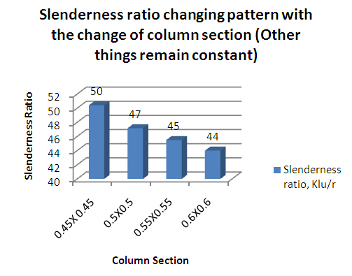 | Figure 9. Slenderness ratio changing pattern with the change of column section (Other things remain constant) |
6. What is the Percentage Error if Slender Column is Designed as a Short Column?
For the above condition in section 6.7 (Load & moment) if the section 0.45 m X 0.45 m is designed as a short column then the steel ratio is 0.0180 but when it is considered as a slender column (Not braced against sides way) then the steel ratio is 0.0215. That means if this column is designed considering first order analysis only then the deviation of steel ratio is more which cannot be neglected. For this reason the second order analysis is mandatory in case of slender column design. The percentage error for the section 4.9.6 is (0.0215-0.0180)*100/0.0180=19.44%.Any deviation less than 5% can be neglected. In this case the deviation is more than 5% and it cannot be neglected during design.
7. Necessity of High Strength Materials in Slender Column
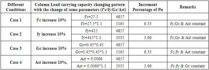
The main benefit of high strength material is to enable smaller dimension of the member and lesser volume of material which facilitate immediate application of design and construction. RCC is the combination of concrete and steel. The two different materials need to bond properly. For instance if 16 mm rebar is used in a column then the clear cover 37 mm is sufficient but if the rebar diameter is 40mm then the clear cover 37 mm is not sufficient. Steel during its life span develops some stress internally even when the imposed load is low and this tendency spreads surrounding the bar which may cause some crack. There is a possibility of formation of hairline crack in the outside of the rebar if sufficient clear cover is not provided.Similarly for lower steel ratio normal grade concrete can be used but for higher steel ratio high strength concrete is needed for proper bonding. Sometimes there is a restriction for the section of the column. In that case the performance of the RCC member needs to be increased without changing the section and there is an efficient way to increase the material strength.From the calculation shown in Appendix E, for every 10% increment of concrete compressive strength or steel yield strength or concrete gross area, the load carrying capacity of column increase as same percentage. In the market or general practice we get ready mix concrete and steel of some specified grade. For calculation purpose we used 10% increment of concrete and steel grade and observe the changes in the performances of the column. But it is ensured that the value of β1 must be revised if the value of f’c is more than 27.5 Mpa.This increment is linear as the equation is first order [Pu=(0.85*f’c*a*b+Astfy].In the slender column definition the small cross section is the matter with respect to length. Different research study is ongoing by engineering material experts to make high strength materials. Fiber reinforced polymer (FRP) is one of the popular techniques right now. [10]
8. Conclusions
From the stiffness analysis it is seen that the length and section of column & beam affect the slenderness ratio. Slenderness ratio calculation is a vital factor because it tells the necessity of slender column phenomenon needs to be applied or not. If there is error in the calculation of the slenderness ratio it will affect the overall column design. The main aim of this study is to know the calculation step of slenderness ratio of column and to get a clear idea that how the slenderness ratio is changed with the change of different parameters.The steel requirement with or without second order analysis there is a much deviation from the required steel area and calculated steel reinforcement. This study helps the designer about the comparative changes in steel requirement and tells the importance and necessity of second order analysis in slender column design.Here further study is needed about the shear reinforcement for the slender column and comparative study can be studied about how much additional shear reinforcement is needed in case of slender column.There is another type of column which is inclined at some angle with the ground. The authors have an intend to involve them for another study about inclined column and shear reinforcement and failure pattern of RCC slender column.
Appendix A
Graph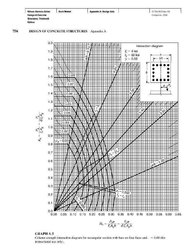 | Graph A.5 |
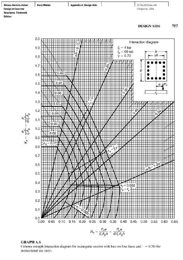 | Graph A.6 |
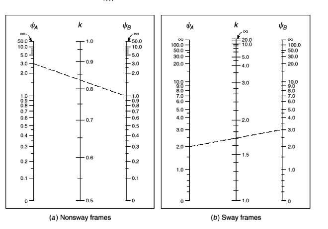 | Graph A.7. Effective Length Factor (K) calculation |
Appendix B
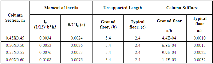
Beam column Stiffness CalculationTable B01. Column Stiffness Calculation (Associated with Figure 6)
 |
| |
|
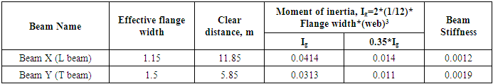
Table B02. Beam Stiffness Calculation (Associated with Figure 6)
 |
| |
|
Rotational restraint factor at point A in X direction,ψA,X = (Stiffness of Column, Ground + Top)/(2*Stiffness of Beam X)In this case, 2 is multiplied with stiffness of Beam X because there are two beams in X direction in the point ARotational restraint factor at point A in Y direction,ψA,Y = (Stiffness of Column, Ground + Top)/(Stiffness of Beam Y)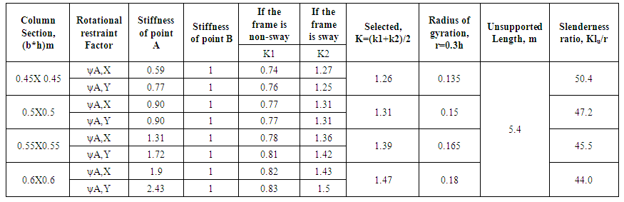 | Table B03. Slenderness ratio changing with the change of column section |
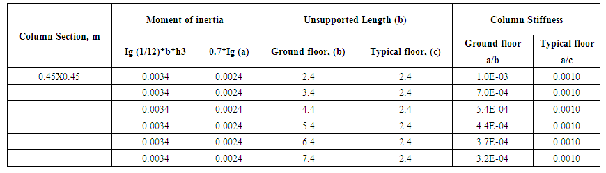 | Table B04. Ground floor column stiffness changing with the change of unsupported length column section (In this study only A-07 column in the ground floor is considered only) |
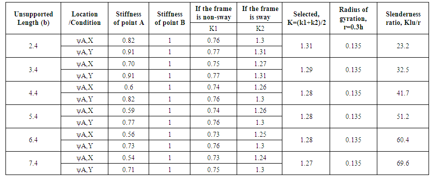 | Table B05. Slenderness ratio changing with the change of unsupported length of Ground floor column |
Appendix C
Building Seismic Load Calculation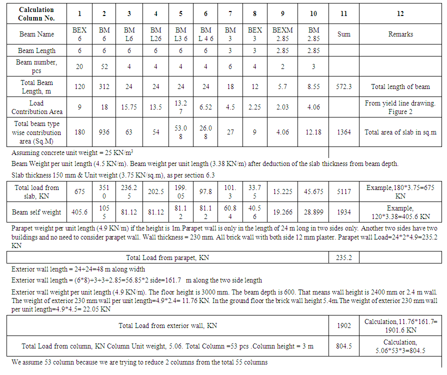 | Table C01. Roof Load Calculation (With calculation step …..) |
Building Seismic Load CalculationTable C02. Roof seismic load calculation (Please read with the drawing …..)
 |
| |
|
Table C03. Typical floor load calculation (Please read with the Figure 4 & 5)
 |
| |
|
Table C04. Ground Floor Load Calculation (Please read with the drawing …..)
 |
| |
|
Table C05. Plinth Label Load Calculation
 |
| |
|
 | Table C06. Base shear calculation |
 | Table C07. Sway / Non sway check |
 | Figure 6. Yield line (Load contribution area for each beam) |
Appendix D
Software Result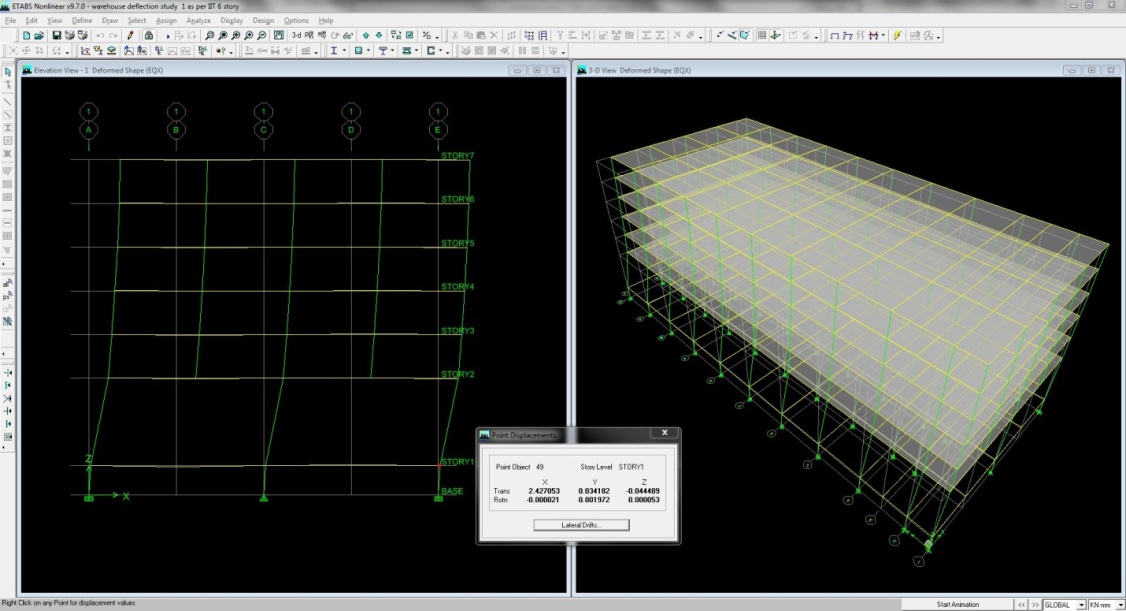 | Figure D01. Story Displacement at plinth level |
 | Figure D02. Story Displacement at ground level |
 | Figure D03. Story Displacement at first floor level |
Appendix E
Table E01. Increment percentage of column load carrying capacity with the increment of different parameters
 |
| |
|
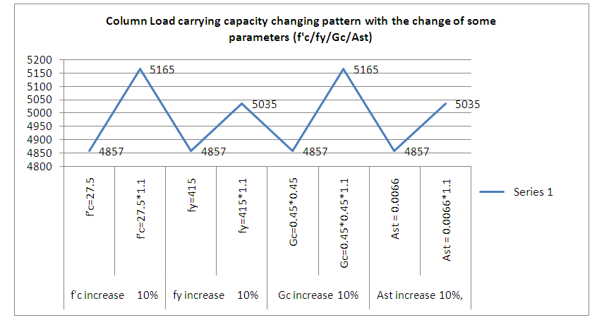 | Table E02. Column Load carrying capacity changing pattern with the change of some parameters (f'c/fy/Gc/Ast) |
References
| [1] | A.B.M. Golam Rabbany, Samiul Islam, Md. Hasan-Uz-Zaman-“RCC Short Column Performances in Different Conditions: Axial, Uniaxial & Biaxial Bending” Journal of Civil Engineering Research, Volume 8(3), published in 2018, pp. 70-85, DOI 10.5923/j.jce.20180803.03. |
| [2] | Murat Saatcioglu- “Design Handbook (Metric)”, Chapter 04- Design of Slender Columns, editor American Concrete Institute / 01-Jan-2010. |
| [3] | A.B.M. Golam Rabbany, Samiul Islam, Md. Hasan-Uz-Zaman-“Pile Cap Performances in Different Consequences” Architecture Research, 2018; 8(2): 51-61, doi:10.5923/j.arch.20180802.02. |
| [4] | Andrew Pytel, Ferdinand L. Singer-“Strength of Materials”- 4th edition, “Chapter 11-Columns,”, Harper Coliins Publishers, Singapore, 2006-2007. |
| [5] | Building Code Requirements for Structural Concrete (ACI 318-95) and commentary (318R-95). |
| [6] | Charles Head Norris, John Benson Wilbur, Senol Utku- “Elementary Structural Analysis”-4th edition, “Chapter 7-Approximate Analysis Of Statically Indeterminate Structures,”, McGraw Hill Higher Education, 2014-2015. |
| [7] | Arthur H.Nilson, David Darwin, Charles W. Dolan-Design of Concrete structures -13th Edition, “Chapter 9-Slender Columns,” McGraw Hill Higher Education, 2006. |
| [8] | Dr. H. J. Shah, Dr. Sudhir K Jain-“Design Example of a Six Storey Building”, Document No: IITK-GSDMA-EQ26-V3.0 Final Report: A - Earthquake Codes, IITK-GSDMA Project on Building Codes. |
| [9] | Keerthi Gowda B S Abhilash A.S. A Comparative Study of Multi-storey RC Structures with Y-Shaped Columns. Proc. of the Conference: International Conference on Trends and Recent Advances in Civil Engineering (TRACE 2016), Amity University, Uttar Pradesh. |
| [10] | Pedram Sadeghian, Amir Fam- “Strengthening Of Slender Reinforced Concrete Columns By Buckling Control Using High-Modulus Bonded Longitudinal Reinforcement” Journal of Structural Engineering, Volume 141(4): 04014127, April 2015, page 18-19, DOI: 10.1061/(ASCE)ST.1943-541X.0001066. |

 Abstract
 Reference
 Full-Text PDF
 Full-text HTML