-
Paper Information
- Paper Submission
-
Journal Information
- About This Journal
- Editorial Board
- Current Issue
- Archive
- Author Guidelines
- Contact Us
Journal of Civil Engineering Research
p-ISSN: 2163-2316 e-ISSN: 2163-2340
2018; 8(3): 62-69
doi:10.5923/j.jce.20180803.02

Determination of Submergence Depth to Avoid Vortices at Horizontal Intake Applying Flow-3D Software
 Abstract
 Reference
 Full-Text PDF
 Full-text HTML
1Azad University, Roudehen Branch, Assistant Professor Civil Engineering, Iran
2Azad University, Roudehen Branch, MSc Hydraulic Structure and Civil Engineering, Iran
Correspondence to: Erfan Razavi, Azad University, Roudehen Branch, MSc Hydraulic Structure and Civil Engineering, Iran.
| Email: |  |
Copyright © 2018 The Author(s). Published by Scientific & Academic Publishing.
This work is licensed under the Creative Commons Attribution International License (CC BY).
http://creativecommons.org/licenses/by/4.0/

Free surface vortices is considered as one of the problems of the industry in part of flood control (over flow), agriculture, electricity and water supply plants that researchers’ effort in this way represents importance of this issue., it can cause excessive vibration, efficiency loss, structural damage, and also flow reduction in hydro turbines, pumps, Culverts and also can be potential risk and damage factor on the safety of power plants. The most important reasons for using the software FLOW 3D in this thesis is the exact study of intake and making connection between software model and Experimental model. Since software has capability to present velocity distribution in line X Y Z and other hydraulic parameters in point of Critical depth (the first depth into that vortex is not formed). In this thesis presented the Numerical model of horizontal intake with a Plexiglas Reservoir by length and width of 3.1 m and depth of 2.2 m and intake pipes with a radius of 0.3, 0.25, 0.194, 0.144, 0.1, 0.05 m and length of 3 m in determining the required depth of flooding to prevent vortex as software modeling. The results of this study can be used to derive a scrutiny relationship between the depth of flooding in the form of equations of first grade and second grade point. This relationship has been extracted after examining the application output and experimental data in terms of depth flood submergence depth (critical depth), intake diameter, Froude number, the Weber number and Reynolds number.
Keywords: Critical Submergence, Free Vortex, Horizontal intakes, Numerical modelling Include
Cite this paper: Hassan Ahmadi, Erfan Razavi, Determination of Submergence Depth to Avoid Vortices at Horizontal Intake Applying Flow-3D Software, Journal of Civil Engineering Research, Vol. 8 No. 3, 2018, pp. 62-69. doi: 10.5923/j.jce.20180803.02.
Article Outline
1. Introduction
- In modern world, water demand increases more and more due to exhausting of natural water Resources. Consequently, they should be used more carefully and efficiently due to the possibility of Facing with problems in the future. Since water is transmitted from seas, lakes, rivers or simply Reservoirs through intakes to be used in power generation, irrigation, domestic and industrial supply, Improvements in the design criteria of the intakes have a great importance to minimize cost and to Use water efficiently. As well as, performance of power plants is face by many difficult and problems. One of the major problems encountered during intake design is the specification of submergence and other design parameters in order to avoid strong free surface vortex formation. Also, electricity production and water demand are arguably two most critical issues of humanity. Collection of water for energy is managed by intakes in reservoirs. Design criteria and economical restrictions may force the designer to end up with intake designs that display undesirable flow conditions, such as vortex. Vortices may be formed due to several reasons, however three main categories were pointed out by Durgin & Hecker (1978) (Guidelines for Design of Intakes For Hydraulic Plants, 1995- Figure.1). The categories are: a) Eccentric orientation of the intake b) Viscous induced velocity gradients c) Formations of eddies by obstructions.
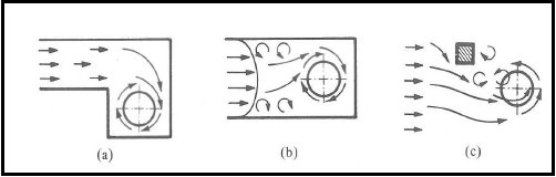 | Figure 1. Causes of Vortices (Durgin & Hecker 1978) |
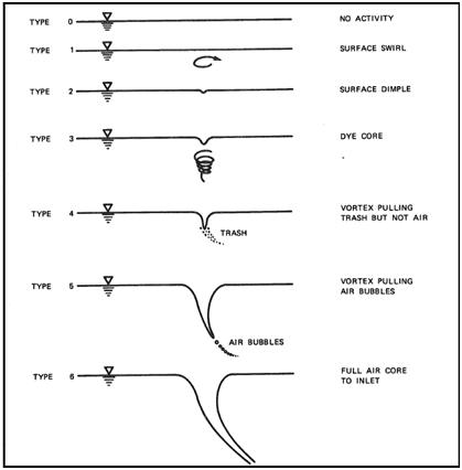 | Figure 2. Vortex strength scale used by Dargin and Anderson for classification of free surface vortices at intakes |
2. Literature Review
- Anwar [4], [5], [6] worked experimentally and theoretically on a steady vortex with an air core at the entrance of an outlet pipe and also on solutions to suppress vortex formation.Blasdell and Donnelly [7] carried out a study in order to investigate the use of hood inlet since this type inlet is simple, economical, and can be easily installed for agricultural purposes. The hood inlet is formed by cutting a pipe at an angle and it is placed such that the longer part is at the top. During experiments on the hood inlet, a number of different types of vortex inhibitors were tested in order to prevent vortex formation at the inlet. Jain et al. [11] conducted experiments with two geometrically similar cylindrical tanks by placing vertically oriented intake pipe at the center of the bottom boundary of the tanks. The critical submergence ratio was found to be a function of the Froude number in the following form from the experimental data which are valid for the range of Froude number; 1.1 ≤ Fr ≤ 20. Gordon [9] has concluded that it is hard to investigate the effect of the geometry on formation of vortices. Therefore, it was decided to focus on other parameters which affect the vortex formation. According to the available data, the following formulas were derived to find the critical submergence ratio:
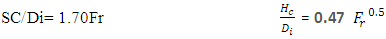 For symmetrical approach flow conditions and,Sc/Di= 2.27Fr In fact, the extracted equation in this paper is much more comprehensive compared to the above equations. Moreover, it contain various parameters of the flow, for instance, weber, Reynolds and Froude numbers.Yıldırım [13], [14], [15], [16] et al. (2009) investigated the effects of dimensions and relative positions of two (dual) Vertical and horizontal intake pipes on the critical submergence. As a result of experiments, the critical submergence of the dual intakes is larger than a single intake pipes because in dual pipe system.
3. Numerical Modeling
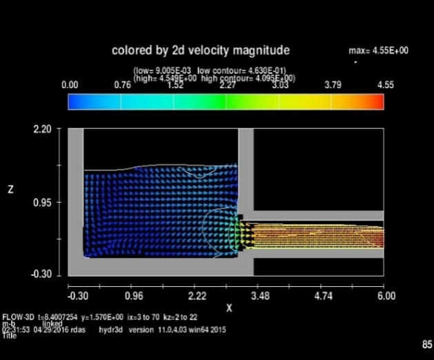
- Figure of Comparisons of Vorticity Contours for Grid Dependency and Coarse mesh out of plane vorticity contour of Horizontal intake Vortex on a side plane close to free surface as well as velocity magnitude are presented (Fig 3 and Fig 4).
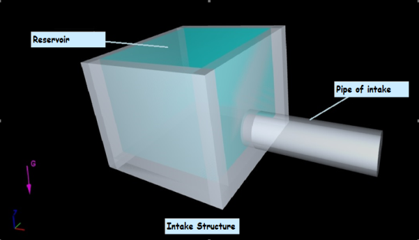 | Figure 3. Numerical Model (perspective view) |
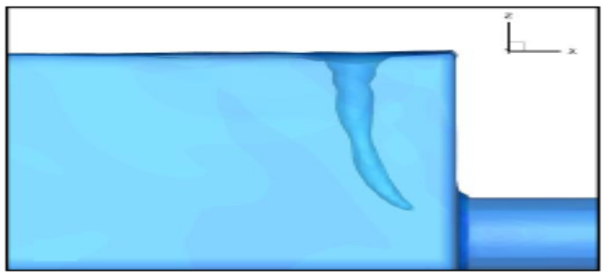 | Figure 4. Vortex formation and Critical submergence with coarse mesh |
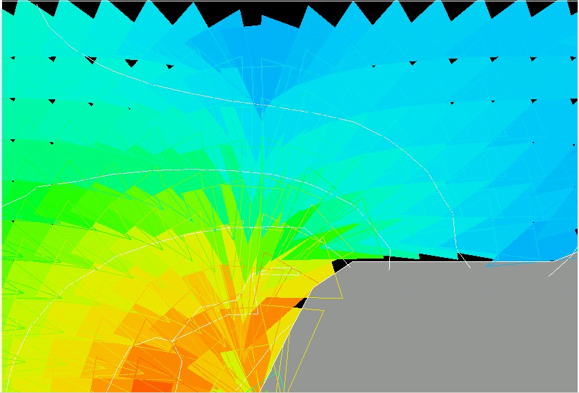 | Figure 5a. Vorticity magnitude contours in Critical submergence depth |
 | Figure 5b. Vorticity magnitude contours in Critical submergence depth |
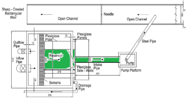 | Figure 6. Top view of ALİ BAYKARA’s experimental intake |
4. Results
- In the present study effect of Froude, weber number and diameters of pipe intake on the formation of free surface vortices at horizontal intakes were investigated numerically. The available data were analysed and equation for critical submergence was derived.The Analysis relationship and equation presented here considers the various variables influencing the critical submergence of the intake structure. And the functional relationship (equation) can be written for Sc/Di as
 WhereSc= critical submergenceDi= diameter of the horizontal intakeFr= Froude numberRe= Reynolds numberWe= Weber numberThe weber number is showed:
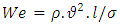 Where the density of the fluid (kg/m3), its velocity (m/s) and surface tension (N/m)l is its characteristic length, typically the droplet diameter (m)The modified Weber number equals the ratio of the kinetic energy on impact to the surface energy.And, The Reynolds number is defined below for each case.
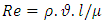 Where the velocity of the object relative to the fluid (m/s), the dynamic viscosity of the fluid (Pa·s or N·s/m2 or kg/ (m·s)).l is a characteristic linear dimension, (travelled length of the fluid; hydraulic diameter when dealing with river systems) (m), the density of the fluid is in (kg/m3).The purpose of the numerical study and obtain this relationship was to initiate development of design information to assist an intake designer in the avoidance of free surface vortices.Figures of difference between experimental data and numerical values of Sc/Di versus rate of Froude number (Fig 7).
 | Figure 7a. Difference between experimental data and numerical values of Sc/Di versus rate of Froude number (Intake pipe diameter=30) |
 | Figure 7b. Difference between experimental data and numerical values of Sc/Di versus rate of Froude number (Intake pipe diameter=25) |
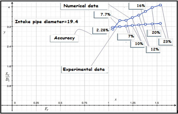 | Figure 7c. Difference between experimental data and numerical values of Sc/Di versus rate of Froude number (Intake pipe diameter=19.4) |
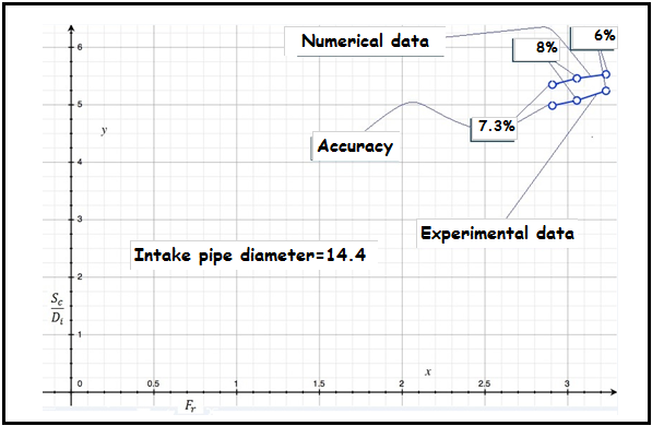 | Figure 7d. Difference between experimental data and numerical values of Sc/Di versus rate of Froude number (Intake pipe diameter=14.4) |
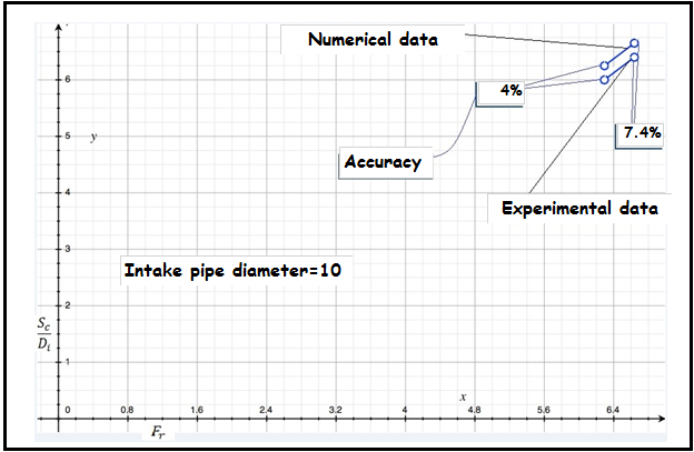 | Figure 7e. Difference between experimental data and numerical values of Sc/Di versus rate of Froude number (Intake pipe diameter=10) |
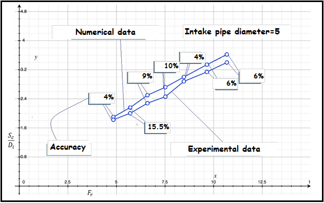 | Figure 7f. Difference between experimental data and numerical values of Sc/Di versus rate of Froude number |
5. Conclusions and Recommendations
- From the experimental and numerical study, the following conclusion can be drawn:1- The purpose of the study was to compile and develop intake design criteria and calibrations model as well as functional relationship to avoid free-surface vortices at horizontal intakes.2- Sc/Di values decrease gradually and almost linearly with increasing side walls length of an intake pipe of known diameter.3- Sc/Di values increase gradually and almost linearly with increasing Fr, Re and We of an intake pipe of known diameter.4- The meshing is divided into two regions: 1) a region where intake vortices are unlikely and a model study in not required expect with extremely poor approach conditions, and 2) a region with a good possibility of intake vortices, where a coarser mesh recommended.5- Region 2, where intake vortices are a good possibility, is very large, encompassing many hydropower facilities. This is because minimum intake submergence to avoid vortex formation is highly dependent upon approach conditions, which are site specific.6- The submergence required to avoid free-surface vortices were:
 For all the arrangements considered.