Anthony Quansah1, Flory Raphael Kazadi2, Fares Taher Mohammed3, Abdulaziz Mohammed Ali3
1Engineering Simulation & Data Management, Org
2Graduate School, Civil Engineering Faculty, Zhejiang University of Science and Technology, Hangzhou, China
3Department of Civil Engineering, Zhejiang University of Technology, Hangzhou, China
Correspondence to: Anthony Quansah, Engineering Simulation & Data Management, Org.
| Email: |  |
Copyright © 2018 The Author(s). Published by Scientific & Academic Publishing.
This work is licensed under the Creative Commons Attribution International License (CC BY).
http://creativecommons.org/licenses/by/4.0/

Abstract
Slope instability in the form of landslides is a major concern among geotechnical problems due to subsidence of the top soil material. An optimum design of gabion mesh wire with nails fixed into the withholding material is one of the prime solutions to this problem. Therefore, the present study applied this reinforcing solution to a landslide prone site located on the Northern side of Hoia hill in Cluj-Napoca, center of Romania which previously has been deciphered by means of drainage technique solution. The study scope was steered at investigating the optimum length, angle of inclination and profile of nail arrangement on a slope under saturated and unsaturated ground conditions by comparing the output results of Bishop, Janbu, Spencer and Morgenstein Price (GLE) analysis principles in GEO-SLOPE through their factor of safety (FOS) and shear strength. Among these four major methods of analysis, no major differences were found in the location of the slip failure surface but some minor differences were found in their FOS’s & the constituiting material’s contributing strengths like frictional strength. After installation of slope nails, it was found that the maximum FOS is obtained when length of all the nails exceeds the depth of the slip circle and the required length for anchorage section is reached. In setting the nail’s angle of inclination as the parametric study item, the best angle that satisfies LEM was found to be between 20o-40o degrees. But the optimum angle of inclination for LEM was found to be 30o for saturated ground and 40o for unsaturated state. The optimum layout of the soil nail was found to be longer at the top and bottom and shorter in the middle or longer at the bottom and shorter at the top, which is contrary to some researcher’s guidelines for soil nail design during top-down construction.
Keywords:
Soil nails, Slope stability analysis methods nail angle, Factor of safety(FOS), Slope stability, Optimum nail length
Cite this paper: Anthony Quansah, Flory Raphael Kazadi, Fares Taher Mohammed, Abdulaziz Mohammed Ali, Optimum Design Analysis of a Nailed Slope Based on Limit Equilibrium Methods: Case Study - Cluj-Napoca Landslide, Journal of Civil Engineering Research, Vol. 8 No. 3, 2018, pp. 49-61. doi: 10.5923/j.jce.20180803.01.
1. Introduction
Landslides are most common experienced hazards which manifest in susceptible areas of important human activities and hence can induce many negative effects. Some landslide stabilization methods are very expensive and require significant time to implement. However, identification of the most important controlling process that is affecting the stability of the slope and determination of the appropriate technique to reduce the influence of that process is necessary. Reinforcing a slope with soil nails is so far one of the most effective ways to stabilize a soil slope from failure and deformation. Soil nailing has been used for quite some time now in the stabilization of retaining walls and existing fill and cut slope (embankments and fills). The whole concept of soil nailing is about reinforcing the soil with very closely packed nails to create coherence in the soil and prevent it from displacement and failure due to natural factors. In this paper, the author examined the parameter sensitivity of composite soil-nailing for the stabilization of landslide sites using limit equilibrium methods. Mouse-click at one of the menu options will give you the style that you want.
1.1. Landslides Failure
The downslope movement of material under the influence of gravity is termed mass wasting and all rapid forms of mass wasting represents landslides. However, the potential for land sliding is not determined by slope angle alone but water plays a significant role. Failure is more likely to occur if the effect of friction on the potential sliding surface is reduced. Cohesion between grains of slope materials may reduce the potential for slope failure. Also loose unconsolidated state of slope materials is a factor for slope failure. Ultimately, presence of excess pore water pressure destabilizes slopes by adding weight, destroying cohesion and reduces friction. Mainly, if addition of excess water raises the ground water table, then drainage techniques are preferred as an effective stabilizing solution. However, sometimes, land sliding can be controlled by modifying the physical properties of the mass material like compaction, consolidation, lightweight backfilling and slope strengthening. Slope nailing is used as a slope strengthening technique to stabilize and increase FOS of soil slope.
1.2. Previous Works with SRM & LEM
Intensive research about the various analysis techniques concerning slope failure and modes of occurrence of slip surface have been made over the past decades. Based on previous works, different analysis methods have been recommended for analyzing the stability of soil-nailed slopes, including the limit equilibrium method (LEM), strength reduction method (SRM), and kinematics method. However, the SRM and LEM are the most common methods used to quantify FOS, shape and location of slip surface, and hence evaluate the anchoring effect in the nailed-slope [3]. The use of the finite difference/finite element methods has also attracted engineers in recent times. The SRM by finite element analysis was used for slope stability examination as early as 1975 by Zienkiewicz et al. [4] and good agreement with slip circle solution is obtained from an idealized homogenous embankment analysis, the SRM has since been applied by other researchers. Naylor (1982) [5] applied the SRM to 2D problem and the failure was determined by the development of very large displacement of protruding points on the failure mass. Donald and Giam [6] conducted the SRM analysis in which the nodal displacement was also used to assess the failure state. Brinkgreve and Bakker (1991) conducted SRM analysis for a river embankment in the tidal zone and for a building trench supported by sheet- pile wall. [4], Matsui and San (1992) [7] conducted SRM analysis in which the slope failure was defined according to the shear strain failure criterion. Ugai and Leshchinsky (1995) [8] conducted 3D SRM analysis for vertical cuts. Griffith and Lane (1999) [9] conducted a detailed description of the SRM analysis and carried out an extensive comparison against LEM typical slope examples. Dawson et al (1999) [9] conducted an extensive simulation for a homogeneous embankment with respect to a wide range of slope angles, soil friction and pore water pressure coefficients to assess the accuracy of the strength reduction technique. Griffiths and Marquez (2007) [10] conducted strength reduction analysis for several 3D slope examples. Both vertical and inclined boundaries were considered in the analysis to investigate the constraint effect of slopes with finite length. Since then many researchers have also come out with interesting but incoherent and surprising results based on the two methods of analysis.
1.3. Slope-Nail System as an Effective Reinforcement
Some researchers like Cheng et al. [11] and Wei et al [12] found interest in soil-nail reinforcement as an effective control measure for slope shear failure. They carried out detailed studies of the SRM and LEM for 2D and 3D slopes, and obtained surprising results in these studies for un-reinforced and reinforced slopes. Other researchers such as Thompson and Miller [13], Srinivasa Murthy et al. [14] also applied the two-dimensional finite element or finite difference methods for the analysis of nailed slopes, and they have come out with suitable results for slopes with reinforcement and geotextile but not much on specific number of nails, nail length, nail angle of inclination and nail arrangement. Some researchers have also adopted the three- dimensional finite element method for nailed soil slope analysis but these researchers focused mainly on the deformation, soil nail interaction but not the factor of safety. Although two-dimensional analysis provides valuable insight into the behaviors of nailed slopes, the effect of the angle of inclination and number of nails on the FOS, stability and deformation of a slope has not been fully discussed.
1.4. Optimization of Slope-Nail Design
Based on the different theories for soil nail interaction model, soil nail behavior has been studied by prominent researchers and henceforth its design is optimized with reference to various parameters, including length, spacing, angle of inclination, diameter and profile of nail arrangement. In consideration of soil-nails layout and geometric orientation for optimum reinforced slope design, Akhtar Hossain et al [15] based on LEM method within the Morganstern-Price method along with Mohr-Coulomb expression to numerically analysis the stability of a reinforced dry slope at different nail angles. Following Akhtar Hossain’s research results, the FOS increases with increase of nail inclination till optimum angle of 30 is reached which enhances the FOS by 18%. Further investigations have proven the relationship between optimal nail orientation and embankment/cut slope gradient which explains that the optimal nail orientation decreases as the slope gradient increases. Chia-Cheng [13] performed numerical study for various slope angles using the non-linear finite element approach. From the results published, it could also be concluded that the optimal nail orientation in relation to the horizontal plane increases with a decrease in the gradient of the soil-nailed slopes. The effects of inclination angle and profile of nails on slope stability is proven to be significant and hence they are considered as optimization parameters in this study.
2. Case Study
2.1. General Description
In Romania, landslides are some of the most common and widespread hazards, which evinced in susceptible areas with important human activities and consequently induced many negative effects in residential areas, territorial communication infrastructure, technical and urban facilities, agriculture. This study presents a landslide prone site located on the Northern side of Hoia hill in Cluj-Napoca, centre of Romania. Geotechnical investigations performed on this site concluded that the main cause of slope instability is the excess pore-water pressure due to both rainfall infiltration and groundwater. [2]. Base on hydrological studies by Bogdan Eugen [16], higher values of drainage density was recorded and this indicates strong force of surface drainage which induces increase in terrain instability. Previous investigations conducted on this site showed possible instability occurrences during exposure to mainly seismic forces and hence drainage system based on siphon drain network was suggested as the solution. In this section, slope-nail reinforcement is suggested as extra effective system together with drainage measures to stabilize the slope. Landslides validation and susceptibility maps of the case study site are presented in figure 1 & 2 to support the background of study. 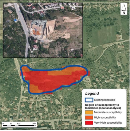 | Figure 1. Landslide Validation, Cluj-Napoca (46 46’32.4”N, 23 33’49.5”E). [16] |
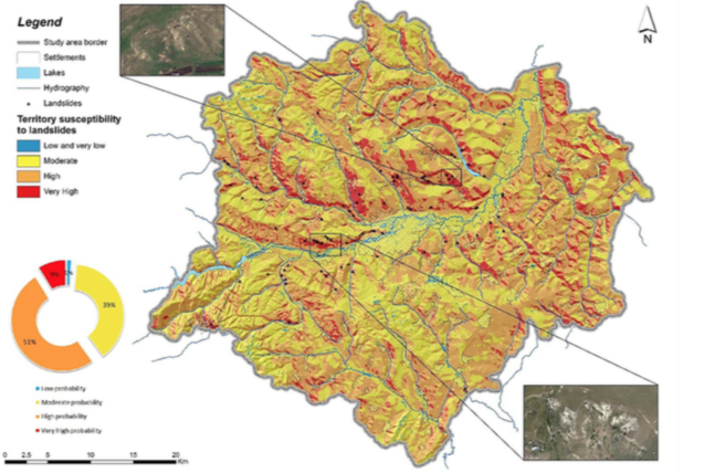 | Figure 2. Landslides Susceptibility Map of Cluj-Napoca Metropolitan Area. [16] |
2.2. Geometry Properties
In order to examine the slope stability and determine optimum design of nails in a slope that can withstand deformation and displacement, a susceptible part of the case study area was modelled in Geo-studio. Per data retrieved from Loretta [2], the upper part of the slope is 7o, middle slope is 11 and the bottom slope is 5o. This conforms to the declivity examination studies by Bogdan Eugen [16], which confirms that the largest part of Cluj-Napoca area is represented by the slope between 5o-10o. The slope is composed of six different soil materials assigned in four various layers with inconsistent depths along the slope. 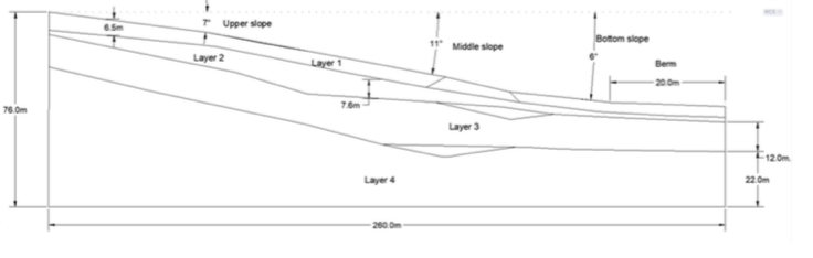 | Figure 3. Schematic presentation of model’s geometry |
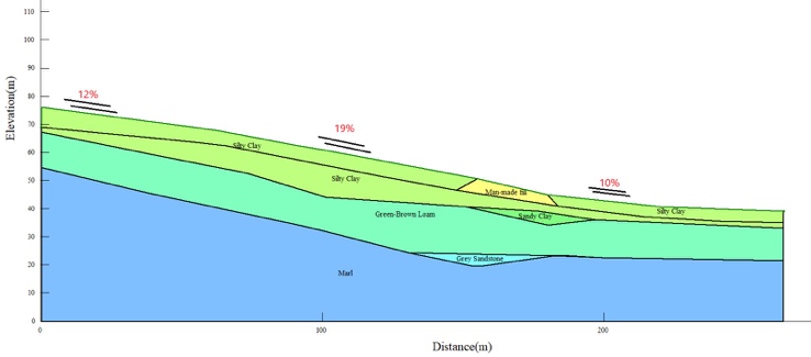 | Figure 4. Material assignment for slope model |
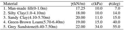
2.3. Material Properties
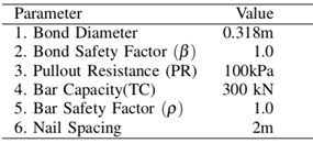
Based on previous experimental research program by Loretta [2], 3 boreholes of 1.70 m depth and 3 jet fill tension meters were installed at depth of 1.30m to 1.70m to monitor the vadose zone and suction values respectively. Also laboratory testing on samples were taken for determination of the mechanical characteristics of soil. Table 1 below presents the geotechnical parameters of the strata. Table 1. Main geotechnical parameters of the ground stata
 |
| |
|
2.4. Stability Analysis
Slope stability analysis was conducted in consideration of four scenarios which results are detailed in this section. All the scenarios are listed below and are analyzed under static conditions and at the initial state. Pre-requisite steps and key routine for stability analysis of unreinforced and reinforced slope are presented in figure 5 & 6. • Saturated condition, Unreinforced
• Unsaturated condition, Unreinforced
• Saturated condition, Reinforced
• Unsaturated condition, Reinforced
Morgenstein-Price, Spencer, Bishop and Janbu methods follow the elements of statics that can be used to derive the factor of safety through either force equilibrium, moment equilibrium or both. These, along with failure criteria, are insufficient to make the problem determinate. Total number of equations available by static definition are 4n whiles the total number of unknown quantities are 6n 1. This brings about indeterminate solution and to solve this, most methods reduce the No. of unknowns by ignoring interslice forces just to compromise this complexity. This hence results in less accurate slope design. The methods used here are expected to give better results because they apply both statics and interslice forces [fig. 7] assumptions to render the problems determinate. The interslice shear force is computed as a percentage of the interslice normal force according to the following empirical equation (Morgenstein-Price). 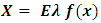 where:
  = the percentage of the function used. f(x) = interslice force function representing the relative direction of the resultant interslice force.
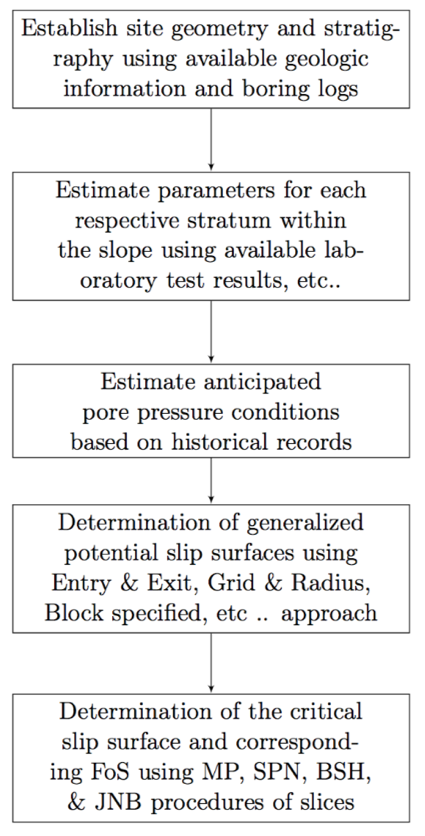 | Figure 5. Unreinforced slope stability analysis procedure |
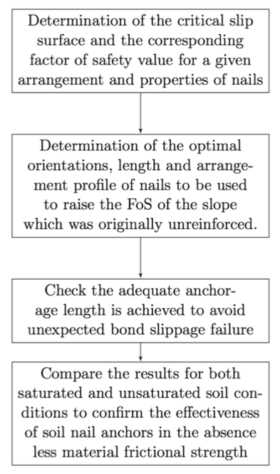 | Figure 6. Reinforced slope stability analysis procedure |
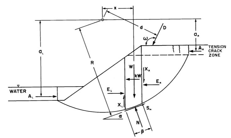 | Figure 7. Schematic representation of slip surface predicted for analysis [fig 8.1 GEOSLOPE design manual] |
2.4.1. Unsaturated Condition
In the scenario of unsaturation, modification of shear strength was accounted for due to suction effects. However, numerous methods are available and implemented in many slope analysis software but their parametric entry are different. Shear strength estimation on unsaturated soil conditions are enumerated by these methods in different manners and they are unsaturated Phi- b, unsaturated Fredlaud, unsaturated vanapalli, unsaturated khalili and unsaturated vilar models. The paper will address only unsaturated Phi-b model because of its relevancy to geo-slope software package. The unsaturated phi-b method defines the parameter fb as the angle defining the increase in shear strength for an increase in matric suction (ua - uw). The unsaturated shear strength angle varies between 0 and f0. According to Fredlaud et. al. [17], the failure criterion Equ1 for unsaturated soil is represented in terms of two stress state variables, i.e. the net normal stress (σ - ua) and the matric suction (ua - uw). Equ1 is a modified Mohr-Coloumbs function.  | (1) |
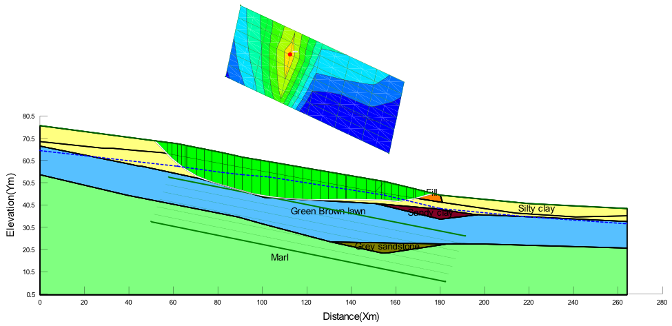
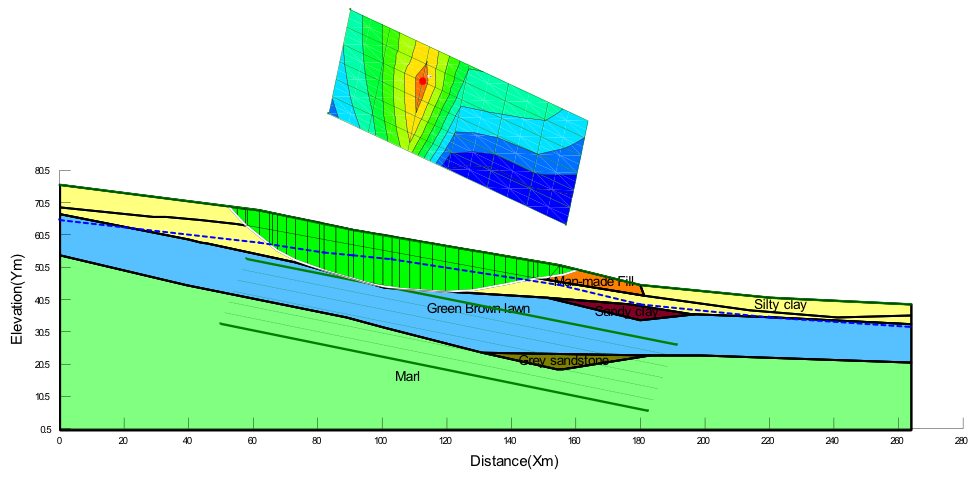
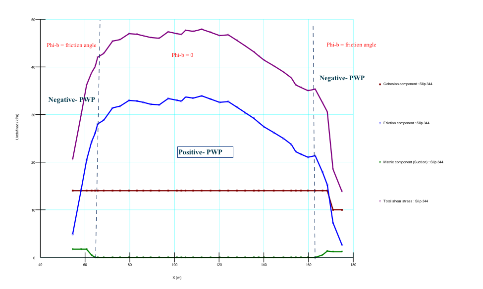
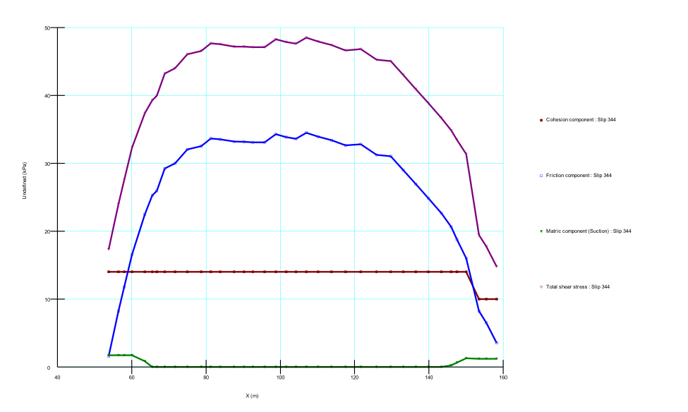
Figure (a) - (d) in appendix shows the computed slip surface and factor of safety for the case where suction effects are included in the Spencer, Morgenstein-Price, Janbu and Bishop analysis methods. Phi-b model 0.0 < fb < f0 was used to define the suction and was approximated as half of the effective friction angle (0.5f0) as shown by published research literatures. The effect of unsaturation on stability of the slope (FOS) is the enhancement of shear strength it brings by reducing slice weight and significantly appreciates the frictional strength as shown in Figure(e) in appendix. This was similar for all the analytical scenarios except that the frictional strength mobilization was different due to the diverse ways of method calculation. In all the cases, the failure slip circle cut within the silty clay layer with the tip of concavity passing through the top of green-brown loam layer and therefore a constant cohesion of 14kPa was applied by the software. Figure 8 shows the actual pore-water pressures applied on each slide of the critical slip surface. The pore pressures change from negative to positive as the suction decreases along the slip the surface and this was same for all the four different analysis principles.
2.4.2. Saturated Condition
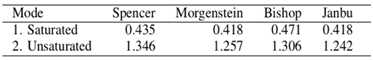
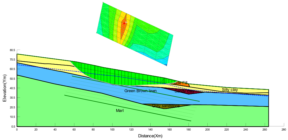
In this scenario, the water table was taken to coincide roughly 1meter down the ground level. The embankment materials were mainly clayey and consolidation process is estimated to take place in a longer time and therefore undrained strength parameters were used in analysis. In the analysis, the ground consisted of silty clay and sandy clay with the failure slip occurring in the 12m thick silty clay layer [figures (a) - (d) in appendix]. It is observed that for a completely saturated slope, the factor of safety (FoS) is largely below 1 without drainage measures, while with drainage method its increasing up to 1.350. When considering saturated properties for soils below the ground water, cohesion is reduced and friction angle is zero due to saturation condition. Table 2. Factor of safety (FoS) of unreinforced slope
 |
| |
|
2.5. Soil-Nailing Support
The factor of safety of the saturated slope without the reinforcement is much lower than 1.0 and mostly such condition is the real scenario for clayey sites. The solution of using drainage measures to create unsaturation condition is time consuming. The soil nail reinforcement technique is much effective if the understanding of the overall stability safety factor with change of these soil nail design parameters is clear. In this section, the nail slope, profile arrangement and length of nail anchorage are studied and optimized for the case study presented above. 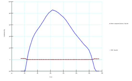 | Figure 8. Pore pressures behavior at the base of slices |
 | Figure 9. Schematic presentation of nail reinforcement |
2.5.1. Reinforcement Loads
Since the reinforcement load applied is dependent on computed overall slope FOS, the bond and bar safety factor is specified as 1.0 to allow mobilized nail force to fully be dependent on the computed slope FOS. The factored applied pullout resistance (FPR) and the maximum factored applied force (FTC) are calculated by expressions below; also the nail specifications are drafted in table 3 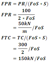
Table 3. Mechanical Properties Specification
 |
| |
|
2.5.2. The Angle of Soil-Nailing
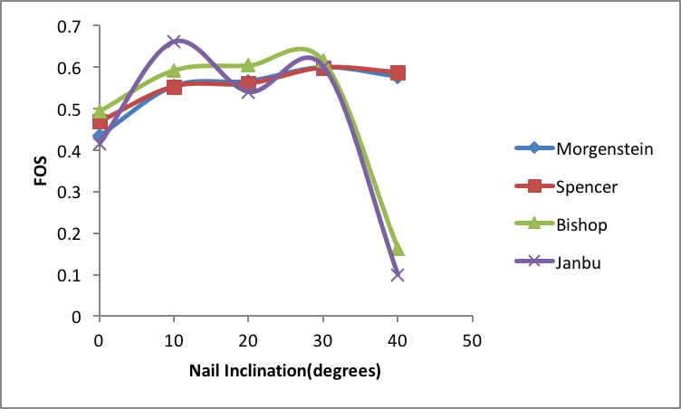
The angle of soil-nailing has a great influence on the safety factor and surface subsidence. Soil-nailing angles are calculated by inclination of 0o, 10o, 20o, 30o, 40o respectively. Through the optimization studies, it was realized that the design parameters of the nails are inter-dependent and its complex interrelationship makes it sophisticated. Accordingly, the slope angles were ranged between 0o – 40o whiles nail spacing, anchorage length, nail length and positions were kept constant. Table 4 shows the design parameters values used during nail inclination study. In keeping with figure 10 & 11, nail inclination of 30o is suitable for saturated ground condition as all but Janbu method achieved high FoS for 10o nail slope. Unlike saturated ground, 20 and 40 nail angles achieved significant stabilization in terms of [Morgenstein & Bishop] and [Spencer & Janbu] respectively. In summary, 30 nail angle is suitable for saturated ground whiles 40o is fit for unsaturated ground. Also, Morgenstein-Price (MP) method is suggested for analysis by the fact that it considers interslice forces and also satisfy moment and force equilibrium which consequently avoids over estimation of FoS. Table 4. Nail Design Parametric Data
 |
| |
|
 | Figure 10. FoS for different nail inclination in SATURATED soil |
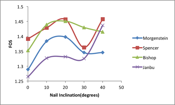 | Figure 11. FoS for different nail inclination in UNSATURATED soil |
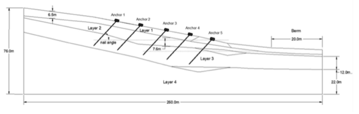
2.5.3. The Profile of Nail Arrangement
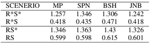
This section focus more on comparison between long at upper row and short at lower row scheme and vice versa. Varying the profile of anchor nail 1 had less influence of slip surface location and shape. The longer the last anchor nail, the deeper the depth of the surface subsidence and the wider it becomes. Nails orientation with longer nail in the upper part of the slope generally lead to an optimal design. Table 5. Comparison of FOS for all the sixteen scenarios of study
 |
| |
|
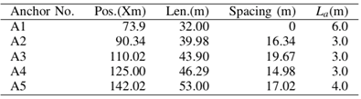
2.5.4. The Length of Nail Anchorage
The required length (Lr) of nail anchorage is based on the decision of equilibrium of FPR and FTC in the section above. From the analysis results it was seen that anchorage length (La) in range of 0 < La < Lr affects the slope stability significantly. Anyway, it is good to increase the La beyond Lr to ensure that the expected nail failure will be a pull & tear but not bond slippage type. From table 5, it is recorded that the first and last anchor nail had La of 6m and 4m respectively but the Lr was 3m. Not much difference was noted with this changes made anchor nails 1 & 5. 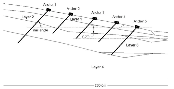 | Figure 12. Nail orientation and profile |
2.5.5. Comparison of FoS
As seen in table 5, reinforcement in saturated soil(RS) produced higher FOS improvement of estimated 43% over unreinforced saturated soil(R*S) even though its lower than 1.0. Unlike reinforcement in unsaturated soil(RS*), diminutive increase of around 3.5% was achieved over unreinforced unsaturated soil(R*S*). From figure 10 & 11, table 5, Mogenstein-Price method comparatively gave the least FOS throughout the analysis cases as Bishop method resulted to the highest FOS. For design safety purposes, Janbu method is recommended for saturated ground because it gave the least FOS whiles Morgenstein-Price method is best for unsaturated state.
3. Conclusions
In this paper, the authors combined the use of drainage measures and soil-nail reinforcement to enhance the stability of landslide prone slope. They further examined the optimum design solution of composite soil-nailing for the slope stabilization using limit equilibrium methods. With only soil-nails in the absence of drainage, the safety factor increased but remained below 1.0. This could be explained as, the forces transfer mechanism in saturated- soil-nail system is less effective due to less cohesion and insignificant frictional interlock of particles. After draining out of about 3m height of ground water, the factor of safety increased beyond 1.0 and further improved by the installation of nail anchors. For best stabilization output, the nail design parameters which have fascinating relevance to the modern time geotechnical operations were henceforth considered. The writers believe that the choice of nail slope during design is very critical. An optimum nail angle of 30o enhanced the stability of fully saturated soil material whiles 40o is suggested for unsaturated condition. Longer anchorage length does not improve FOS or enhance control of deformation (COD) and hence it is economically wise to base choice of anchorage length on the equilibrium of pull-out and tensile capacity. Longer top-bottom nails and shorter middle nails or longer top nails and shorter bottom nails is found to represent the optimum layouts of soil nailing, which is contrary to some researcher’s guidelines for soil nail design during top-down construction. For design safety purposes, Janbu method is recommended for saturated ground because it gave the least FOS whiles Morgenstein-Price method is best for unsaturated state.
ACKNOWLEDGEMENTS
This research was partially supported by Engineering Simulation and Data Management Team, ESDM (www.myesdm.com) who provided insight and expertise that greatly assisted the research, although they may not agree with all of the interpretations/conclusions of this paper.
Appendices
 | (a) Morgestein-Price method; FOS = 1.257 |
 | (b) Spencer method; FOS = 1.346 |
 | (c) Bishop method; FOS = 1.306 |
 | (d) Janbu method; FOS = 1.242 |
 | (e) Morgestein-Price |
 | (f) Spencer method |
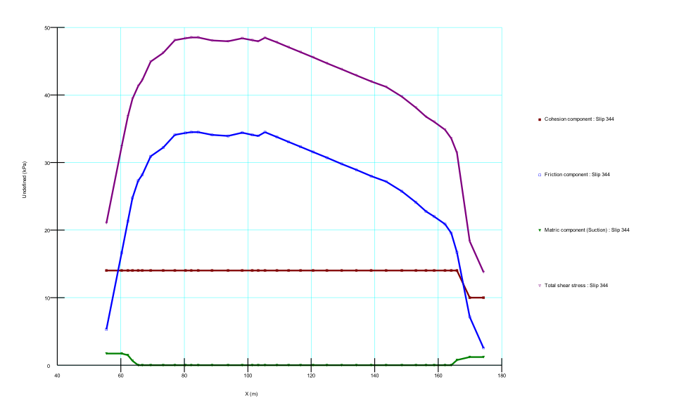 | (g) Bishop method |
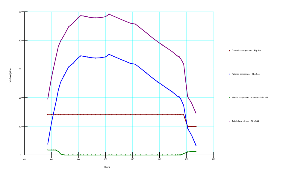 | (h) Janbu method |
References
| [1] | P. T J and G. J W 2005, Landslide Stabilization Using Soil Nail and Mechanically Stabilized Earth Walls: Case Study J. Geotech. Geoenvironmental Eng. 131 141–50. |
| [2] | Batali L and Andreea C 2016, Slope Stability Analysis Using the Unsaturated Stress Analysis. Case Study Procedia Eng. 143 284–91. |
| [3] | Zhang R, Zhao J and Wang G 2016, Stability Analysis of Anchored Soil Slope Based on Finite Element Limit Equilibrium Method Math. Probl. Eng. 2016 1–8. |
| [4] | Zienkiewicz O C, Kelly D W and Bettess P 1977, The coupling of the finite element method and boundary solution procedures Int. J. Numer. Methods Eng. 11 355–75. |
| [5] | Naylor D J 1982, Finite Elements and Slope Stability Numerical Methods in Geomechanics (Dordrecht: Springer Netherlands) pp 229–44. |
| [6] | Donald I B and Giam S K 1988, Application of the nodal displacement method to slope stability analysis Proc. Fifth Aust. Zeal. Conf. Geomech. 456–60. |
| [7] | MATSUI T and SAN K-C 1992, Finite element slope stability analysis by shear strength reduction technique. SOILS Found. 32 59–70. |
| [8] | UGAI K and LESHCHINSKY D 1995, Three-Dimensional Limit Equilibrium and Finite Element Analyses: A Comparison of Results. SOILS Found. 35 1–7. |
| [9] | Dawson E M, Roth W H and Drescher A 1999, Slope stability analysis by strength reduction Géotechnique 49 835–40. |
| [10] | Griffiths D V. and Marquez R M 2007, Three-dimensional slope stability analysis by elasto-plastic finite elements Géotechnique 57 537–46. |
| [11] | Cheng Y M, Lansivaara T and Wei W B 2007, Two-dimensional slope stability analysis by limit equilibrium and strength reduction methods Comput. Geotech. 34 137–50. |
| [12] | W. Wei, Y. Cheng, and L. Li, “Three-dimensional slope failure analysis by the strength reduction and limit equilibrium methods,” Comput. Geotech. 36 no. 1-2, (Jan, 2009) 70–80. http://linkinghub.elsevier.com/retrieve/pii/S0266352X08000384. |
| [13] | Fan C-C and Luo J-H 2008, Numerical study on the optimum layout of soil–nailed slopes Comput. Geotech. 35 585–99. |
| [14] | Yang M Z and Drumm E C 2000, Numerical Analysis of the Load Transfer and Deformation in a Soil Nailed Slope Numerical Methods in Geotechnical Engineering (Reston, VA: American Society of Civil Engineers) pp 102–15. |
| [15] | A. Hossain, “Numerical Analysis of the Effects of Soil Nail on Slope Stability”. |
| [16] | B. E. Dolean, “Landslide Susceptibility Assessment Using Spatial Analysis and GIS Modeling in Cluj-Napoca Metropolitan Area, Romania”. |
| [17] | Zhang L L, Fredlund D G, Fredlund M D and Wilson G W 2014, Modeling the unsaturated soil zone in slope stability analysis 1 Can. Geotech. J. 51 1384–98. |

 Abstract
 Reference
 Full-Text PDF
 Full-text HTML