Haider M. Mekkiyah, Husam Mahdi
Department of Civil Engineering, University of Baghdad, Baghdad, Iraq
Correspondence to: Husam Mahdi, Department of Civil Engineering, University of Baghdad, Baghdad, Iraq.
| Email: |  |
This work is licensed under the Creative Commons Attribution International License (CC BY).
http://creativecommons.org/licenses/by/4.0/

Abstract
The protecting of ancient structures is considered a very important issue as these represents the heritage of the countries. Hence, the performance and the effect of the surroundings changes around such structures have to be understood. In this study, an investigation was performed for the problem of tilting the minaret of the AL-Khulafa mosque in Baghdad, which is tilted about 1.5 m. Detailed geophysical methods were applied to detect the tilting problems of the minaret foundation. Three tests were carried out; ground penetration radar, soil electrical resistivity, crosshole seismic and triaxial tests. The results showed that the water seepage under/around the minaret due to dewatering process around the mosque have a major source for the problem. This groundwater mixed with sewage material, is found to move towards municipality pump that is located nearby the mosque fence within 35 m distance. The tests showed the apparent spread of cavities and soft zones under/around the minaret foundation. Finally, the shape and depth of foundation were able to explore from crosshole test, which is extended to a depth of 8.5 m.
Keywords:
Dewatering, Minaret, Geophysical survey
Cite this paper: Haider M. Mekkiyah, Husam Mahdi, The Tilting Problem of AL- Khulafa Mosque Minaret, Journal of Civil Engineering Research, Vol. 8 No. 2, 2018, pp. 33-39. doi: 10.5923/j.jce.20180802.03.
1. Introduction
Monuments and historical construction, with their cultural, historical and artistic significance, need a particular protection. High rise structures, such as masonry towers, minarets, have a special vulnerability, so that they are considered more important than other structures. Minarets and high towers are considered a special case of buildings and installations known in the world, which may be segment cylindrical, square, or slatted built of stone, brick with plaster and lime, or concrete. High buildings such as towers and minarets are affected by a number of loading cases. Most importantly, wind loads, which cause shear forces, tensile forces, and forces of pressure. In addition to thermal change that contributes to these forces. [1] Explain that the movement of the tower Pisa located in Pisa, with 60 m high, has a 20 m diameter, of masonry foundation and weighs of 145 MN. It is lateral deflection is due to phenomenon of ‘leaning instability’ rather than bearing capacity failure. In a clearer meaning, ‘leaning instability’ of a tall structure occurs at a critical height when the overturning moment generated by a small increase in inclination is equal to or larger than the resisting moment generated by the foundations. Regardless, how carefully the structure is constructed; once it reaches the critical height the smallest disorder will induce leaning instability. [2] Studied the leaning of tower St. Moritz and explains that leaning is due to landslide displacement and location on the side of a hill with unstable soil conditions. The Landslide is considered one of the great geotechnical hazards affecting economy and life in the subjected areas. [3] Explained the leaning of Zul Kifl, one of the historical and cultural buildings in Iraq, is located in the government of Babylon. It has a height of 25 m tilted about 4.5 degree. The minaret leaning because of the weak soil be neath minaret, due to changes in underground water levels, and cases of erosion that has suffered for several years, added to this the presence of the amount of soil buried with the waste, which forms a negative state of the soil. [4] Conducted a study about Big Ben clock tower and conclude that leaning of tower caused by the nearby excavation of the tunnels of the Jubilee line extension. [5] Studied the leaning of Al-Hadba minaret in Iraq, and concluded that the effect of wind load led to the development of a leaning in some minarets in the city, including the Al-Hadba minaret that is located in the wind direction. Also, the groundwater which had raised to about 5 m below the surface of the earth. The source of this water comes from drainage of water pipes and sewage because the area which the water flows with a level higher than the level of the minaret foundation. This water led to the removal of parts of the soil, developing the formation of cavities under minaret, and also weakened the building materials of the foundation.
2. Historical Background
The historical minaret of the Al-Khulafa mosque, as shown in Figure (1), built in 1279 AD, has a height of about 34 m. The minaret itself is surrounded by a courtyard 13.0 x 14.0 m. It has been modernized and restored to a cylindrical shape so that it contains a collection of decorations and beautiful forms. Inside the minaret there are two helical stairs that rotate inside the minaret's body in opposite directions. The Al-Khulafa minaret is influenced by dewatering process for many years back from the surrounding area around the mosque.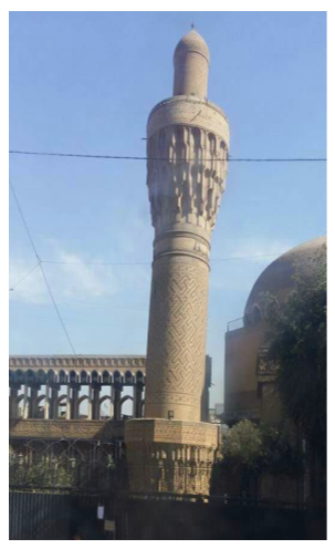 | Figure 1. Tilting Minaret of Al-Khulafa Mosque, Built in 1279 AD |
3. History of the Inclination
The date of the minaret's inclination was not specifically known, the first survey for the minaret was done in 2013 with inclination of 1.24 m. Later, in recent years, the inclination has gradually increased especially in last two years as shown in Figure (2). In 2017, the observation survey have conducted for each month, the monitoring showed that the inclination was increasing from (5-10) mm /month.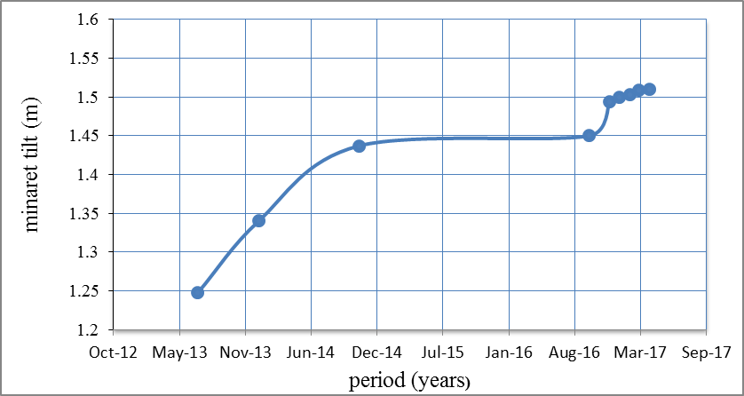 | Figure 2. Measured Horizontal Movements of Minaret between 2013 and 2017 |
4. Case Study: Al-Khulafa Minaret
It was found during the site visits for the minaret large failures in the masonry decoration especially at the tilting side as shown in Figure (3), as a result from changing in centre of gravity location of the minaret and generation of high moment on foundation soil and finally developing a lot of cracks in the body of the minaret. Also, it was found that the minaret suffered from seepage of water, especially during the winter/rainy season where the water remains constant at about 20-25 cm height at backyard area surrounding the mosque. Another impressive case is noticed; from the dewatering process of nearby buildings, houses and shops around the minaret. Finally this process causes increasing the effective stress of soil and led to a settlement of foundation of minaret, because of decrease in buoyancy. The development of stress will be associated with strain. The rate of settlement is based on the stiffness and stress history of soil. The process of dewatering is considered very large in the area surrounding the minaret and is estimated at hundreds of cubic meters per day. Also the plumbing leaks and/or broken water lines; plumbing leaks under or near foundations can saturate soils around it and potentially weakening their load-bearing capacity of soil. Often, plumbing leaks push soil out from under the foundation, creating a void below minaret foundation or any structure foundation causes the tilting or sinking.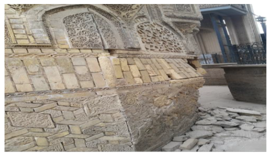 | Figure 3. Failures in masonry decoration of tilting side of minaret |
4.1. Geotechnical Investigation for Site Area
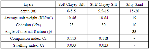
Two geotechnical boreholes were drilled to a depth of 20 m. Laboratory tests were achieved to determine grading, consolidation, shear strength parameters. From field inspection and laboratory testing the following geotechnical soil parameters are listed in Table (1). The test boring showed that, generally, the soil profile is consist of three layers, as shown in Figure (4) the upper layer is considered soft clayey silt, extends to depth of 5.5 m, followed by a layer of stiff clayey silt, this layer extends to a depth of 15 m. Then a layer of medium sand is exist extend down to the end of boring 20 m. Groundwater levels have been recorded at the end of boring in the next day and found to be at depth of about 2.0 m below ground level.Table 1. Geotechnical Soil Parameters
 |
| |
|
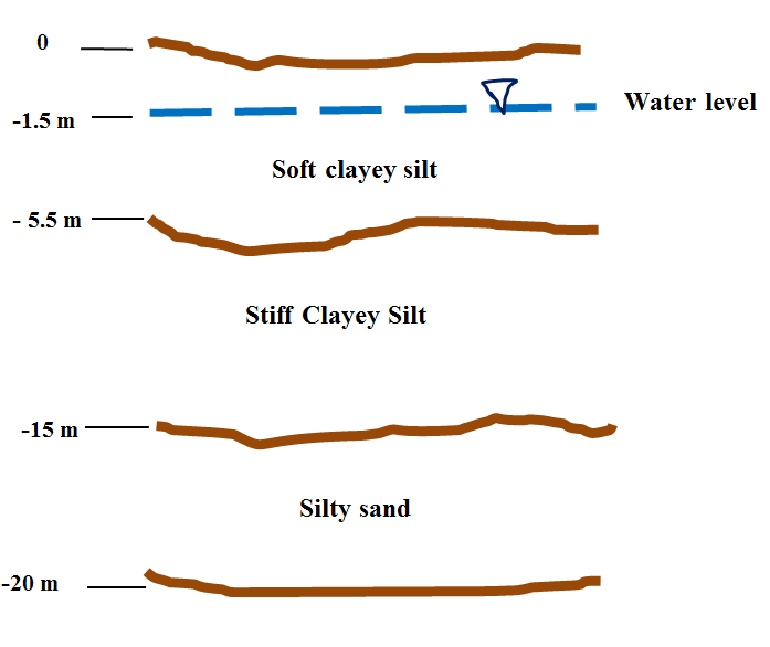 | Figure 4. Soil Profile below the Minaret Foundation |
4.2. Geophysical survey of Al-Khulafa Minaret
The target of the survey is to find the lateral extent and depth of the minaret foundations, and the subsurface soil conditions around the minaret. The GPR (Ground Penetrating Radar) and 2D resistivity imaging were used for surface survey around the minaret location. This survey is used to detect the lateral extent of the minaret subsurface foundation, and also to indicate any subsurface features within the area (13 x 14 m) that surrounding the minaret. Finely the seismic cross-hole test was used to detect the minaret foundation depth, the shear and compression wave velocities of the subsurface soil layers were measured down to a depth of 12.0 m.
4.2.1. GPR Survey
Ground penetrating or probing radar (commonly called GPR) is a high resolution electromagnetic technique that is designed primary to investigate the shallow subsurface of the earth, building materials, roads and bridges [6]. GPR is relatively new geophysical tool that has become increasingly popular due to its high resolution and the need to better understand near-surface conditions, [7]. The test was performed in the form of longitudinal and transverse sections to cover all the ground area around the minaret to get a plan that shows profiles weakness under the surface and lateral extension of the foundations and a depth of at least 3 m and is referred to in Figures (5), (6).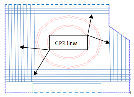 | Figure 5. Locations of GPR Profiles around the minaret |
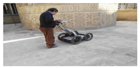 | Figure 6. GPR Survey at Al- Khulafa Mosque Site |
4.2.2. Soil Resistivity
The resistivity imaging survey was carried out around the minaret along six profiles as close as possible to the minaret. This survey is chosen as a complementary method to the GPR since the GPR method has some limitations in conductive soil. The test was performed in the form of six profiles by making holes in the ground near the minaret as shown in Figure (7).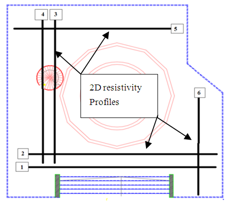 | Figure 7. Locations of the Surveyed Resistivity Profiles around the Minaret |
The work has included drilling the holes with a diameter of 1 cm and depth of 15 cm by use a portable drilling machine, then inserting the electrodes in holes with a distance of 25 cm between them as shown in Figure (8).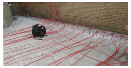 | Figure 8. Electrodes Distribution at the Minaret Site |
4.2.3. Seismic Crosshole Test
Cross hole seismic test is carried out at Khulafa mosque site. This survey determines shear and compressional wave velocities versus depth profile. From these measurements, soil physical parameters can be determined. The down hole system consists of a borehole source, capable of generating shear and compressional waves, and a five component geophone receiver. ASTM D-4428 standard is followed in this test [8]. The source and the geophone are lowered to a depth of (12.0 m) in the two boreholes at about 11.0 m apart on a line as shown in Figures (9) and (10). The measurements are taken stepwise at every 0.25 m intervals up to the top of the boreholes.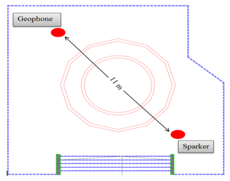 | Figure 9. Borehole Geophone at Borehole -1 and Sparker at Borehole -2 |
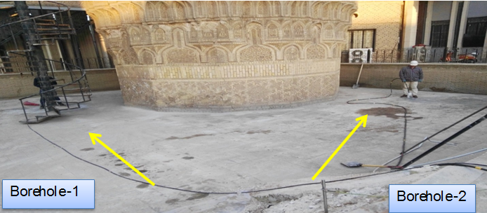 | Figure 10. Locations of the Boreholes |
5. Results and Discussion
The final results of the GPR survey are represented in Figure (11). The locations of the buried water passage ways (blue spots) are also shown along with the areas of subsidence. In Figure (12) the possible subsurface water seepage directions are represented. These are plotted according to the water levels differences that were detected in the GPR radar grams.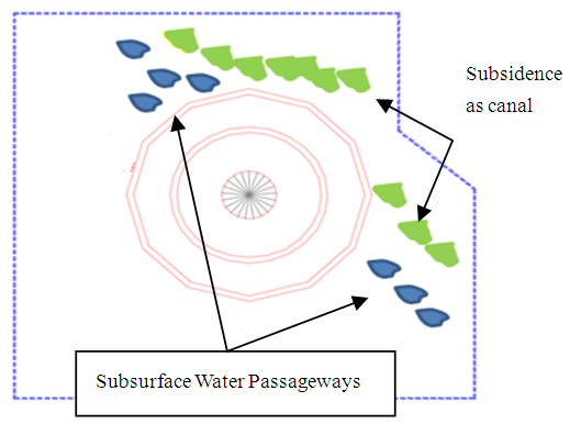 | Figure 11. Main Subsurface Features that Detected by the GPR Survey: The Blue Spots Represented Subsurface Water Passageways and Green Represented loose Soil and Subsidence |
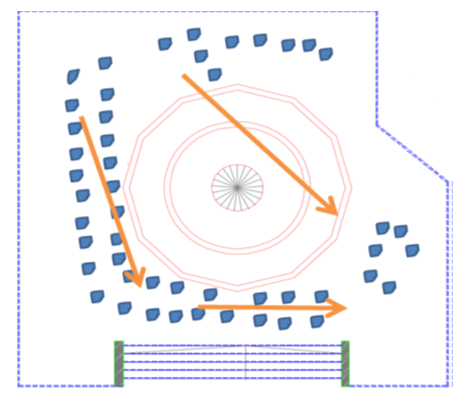 | Figure 12. Possible Groundwater Movement Directions from GPR Test |
The results of surveyed resistivity lines are shown in Figure (13). The main subsurface features are plotted on the minaret layout as a sketch, which also indicates the possible lateral extent of the minaret foundation. Figure (14) showed the underground water movement directions are indicated, which is agreement with the results obtained in the ground radar penetration test in Figure (12). Through these tests, it was found that water movement comes from the back areas surrounded by the mosque; then moves towards the minaret and then changes its direction to the adjacent area of the mosque (i.e. towards the municipal's pump). The municipal's pump is located within 35 m from the side the mosque, as shown in Figure (15). 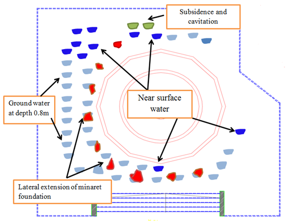 | Figure 13. Main Subsurface Features of Soil Resistivity |
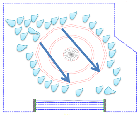 | Figure 14. Possible Groundwater Movement Directions from Electrical Resistivity Test |
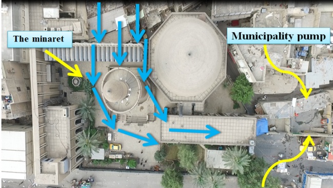 | Figure 15. Aerial Photo of the Pump Location and Direction of Water Movement |
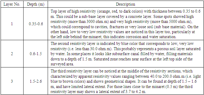
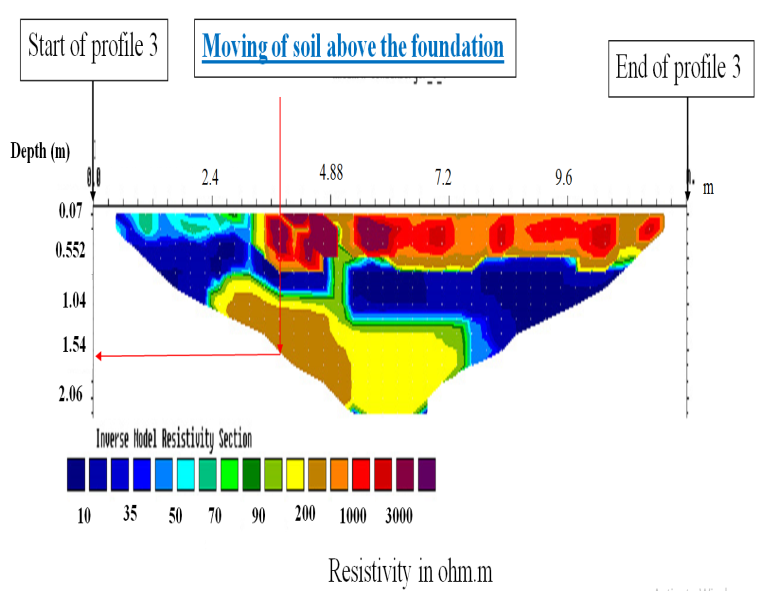
In the Figure (7) previously shown, the profiles (3 & 4) gaves important results about upward subsurface soil movement. The profile 3 starts from the top side, as shown in Figure (16) the first resistivity layer shows cavitation and fractures particularly at the middle parts. While the first few meters show water saturation that reaches the ground surface. The second layer (blue and dark blue) represents saturated filling materials. The third layer (green to brown colors) corresponds to the outer extent of the minaret foundation or the old natural soil. Apparently there is upwelling of the soil/foundation material at this side of the minaret foundation.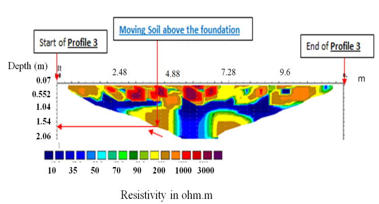 | Figure 16. Apparent Resistivity in Profile 3 |
While in profile 4, it starts from the right side, as shown in Figure (17) the first resistivity layer shows loose soil and fractures, and at the right side (i.e. behind the minaret). At a distance of 5.0 m a water passage way is very clear and followed by cavitation. The second layer (blue and dark blue) represents saturated filling materials. The third layer (green to dark green colors) corresponds to the outer extent of the minaret foundation or the old natural soil. It shows upwelling movements toward the right side (relative the minaret), Table (2) shows a detailed explanation about it.Table 2. Layers Description from Soil Resistivity Test
 |
| |
|
 | Figure 17. Apparent resistivity in Profile 4 |
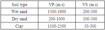
The result of crosshole depending on the velocities of P-wave and S-wave were calculated depending on the first arrival times and the horizontal distance between sparker and geophone boreholes, in Table (3) the typical values of shear and compression wave are shown for different soil [9]. it measured P-wave and S-wave velocities along the 12.0 m, the soil profile show clearly three main values ranges as shown in Figure (18). The first values range starts from depth 12.0 m to 8.0 m; the second range is between 8.0 m to 4.5 m depth; and the third range is from 4.5 m to 0.25 m. The top 0.25 m corresponds to surface concrete and tiles layer. For the calculated shear modulus, also shows three ranges more clearly. The shear wave velocity (S-wave) is more sensitive for the rigidity, and particularly the horizontal component of this wave type. The final values expressed in Figure (19).Table 3. Typical Range of Vp and Vs for Different Types of soil and rock (Sharma, 1997)
 |
| |
|
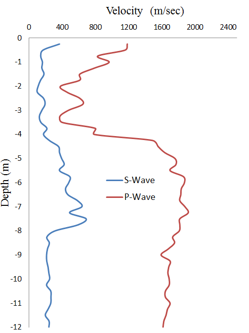 | Figure 18. Variations of P-wave and S-wave Velocities with Depth |
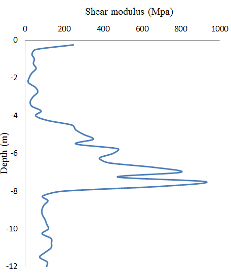 | Figure 19. Variation in Dynamic Shear Modulus with Depth |
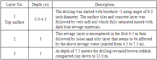
In Table 4, the soil layers are shown under the minaret directly, it explained from the seismic velocities that mentioned previously.Table 4. Layers Description from Seismic Cross hole Test
 |
| |
|
Finally, the geophysical surveys showed that minaret foundation reaches a depth of 8.5 m from the ground surface. At depths from 0 m to 4.5 m the foundation diameter is around 6.9 m, at depth 4.5 m to 8.5 m the foundation diameter is around 10.6 m. This is surrounded by the old natural soil and filling materials. Figure (20) shows a sketch for the details of the minaret foundation shape. The seismic cross-hole test showed non-homogenous physical stiffness of the foundation bricks. It seems that the foundation bricks at depth 4.5 m to 5.5 m lost their rigidity. This is possibly due to the effect of the groundwater movement and the biological and biochemical reactions with minaret brick. At depths from 3 m to 3.5 m and at 2 m to 2.25 m the soil and the foundation bricks showed weak properties. It seems that the maximum corrosion, erosion, biochemical effects are concentrated to these depths. Figure (21) shows the possible weak zones within the minaret foundation depending on the seismic crosshole test results.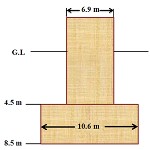 | Figure 20. Shape and Depth of the Minaret Foundation belowground Level |
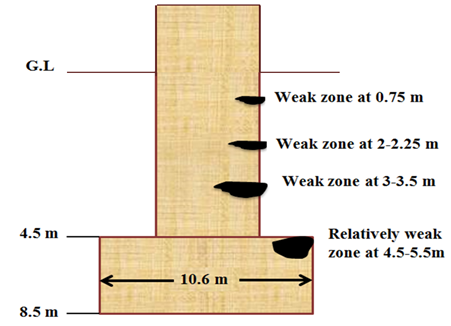 | Figure 21. Weak Zones Location with the Minaret Foundation as Deduced from Seismic Crosshole Test |
6. Conclusions
The subsoil of the minaret suffering from the presence of cavities as a result of washing the soil due to dewatering process nearby the mosque. The water channels are composed are filled with water below ground level in form of paths, which allow water to flow through them, such seepage poses a significant risk to the stability of minaret foundation. Clear indications of weak zones within the brick foundation of the minaret have been found in this survey (from 0.25m to 5.5 m depth), Foundation bricks movement or distortion has possibly happened there. Upward soil movement was noticed inside the courtyard surrounding the minaret at opposite side of tilting. All of these problems are due to dewatering process which poses a real danger to the stability of the minaret.
References
| [1] | Burland, John B., Michele B. Jamiolkowski, and Carlo Viggiani. "Leaning Tower of Pisa: behaviour after stabilization operations." ISSMGE International Journal of Geoengineering Case Histories 1.3 (2009): 156-169. |
| [2] | Alonso, Eduardo E., Núria M. Pinyol, and Alexander M. Puzrin. "A constrained creeping landslide: Brattas-St. Moritz Landslide, Switzerland." Geomechanics of Failures. Advanced Topics (2010): 3-32. |
| [3] | Elahi, H. Sabermahani, M. Atashband, Shaham. "Improvement of subsoil of minaret of Zul Kifl using micro pile and injection of cement slurry". 8th National Congress on Civil Engineering, Babol Noshirvani University of Technology, (2014). |
| [4] | Burland, J. B. A tale of two towers: Big Ben and Pisa. Royal Academy of Engineering, 2002. |
| [5] | Al-layla, khattab and khaleel. "Stability of Al-Hadba minaret a-parametric study." Engineering and Technology Journal (2010): 968-981. |
| [6] | Daniels, David J. Ground penetrating radar. John Wiley & Sons, Inc., 2005. |
| [7] | Ezzedine, Souheil, Yoram Rubin, and Jinsong Chen. "Bayesian method for hydrogeological site characterization using borehole and geophysical survey data: Theory and application to the Lawrence Livermore National Laboratory Superfund site." Water resources research 35.9 (1999): 2671-2683. |
| [8] | ASTM D4428 / D4428M - 14 Standard Test Methods for Crosshole Seismic Testing. |
| [9] | Sharma, Prem V. Environmental and engineering geophysics. Cambridge university press, 1997. |

 Abstract
 Reference
 Full-Text PDF
 Full-text HTML