Makenya A. R.1, John Paul M.2
1Department of Civil Engineering, Ardhi University, Dar es Salaam, Tanzania
2Advanced Engineering Solutions Ltd, Coca Cola Rd, Mikocheni B Area, Dar es Salaam, Tanzania
Correspondence to: Makenya A. R., Department of Civil Engineering, Ardhi University, Dar es Salaam, Tanzania.
| Email: |  |
Copyright © 2017 Scientific & Academic Publishing. All Rights Reserved.
This work is licensed under the Creative Commons Attribution International License (CC BY).
http://creativecommons.org/licenses/by/4.0/

Abstract
Concrete mix design is very important as it influences the performance property of designed concrete structures. It is very common that mix design is basically done by hand or developed excel sheets. These methods can be risky and taking long time, therefore a need for an alternative time effective method. This paper presents a developed easy-use program for concrete mix design of high strength concrete (HSC) using a MATLAB program. The program has been developed basing on the Erntroy and Shacklock (1954) mix design method. The tabular and graphical data from the method was converted into appropriate modal equations. An algorithm based on the method was developed utilising the modal equations and specific assumptions which was then coded in a MATLAB program. Thereafter, the developed program was tested using examples from reputable literature. The final results obtained using the program match with the results obtained using a manual approach. It was also noted that, the computation time using the program was faster compared to the manual approach. The design of HSC using a developed MATLAB program shows excellent results and can be used as an alternative to manual approach. This justifies the development of computer aided concrete mix design approaches to save time and increase efficiency.
Keywords:
High strength concrete, Mix design, MATLAB program
Cite this paper: Makenya A. R., John Paul M., Potentiality of Using a Developed MatLab Program for the Design of High Strength Concrete Mixes, Journal of Civil Engineering Research, Vol. 7 No. 3, 2017, pp. 81-98. doi: 10.5923/j.jce.20170703.01.
1. Introduction
High strength concrete (HSC) has many advantages in the construction industry worldwide. An engineer can design small size of structural member which makes it easier in the construction process. With an increase in concrete strength (at the age of 28 days), engineers can design a smaller structural member that can still carry the same amount of load. And the use of HSC provides economic benefits when used in structural members. In the past, few researchers developed computer applications for mix design of concrete. Abdullahi and Al-Mattarneh and Mohammed and Sadiku developed an ‘m-file’ in a MATLAB program for mix design of structural light weight concrete [1]. Besides, Zealakshmi and Ravichandran and Kothandaraman [2] developed a program in MATLAB for concrete mix design for high strength concrete up to 60Mpa (Zealakshmi, et al., 2013). A concrete mix design programm using MATLAB for concrete strength between 25MPa to 45MPa was developed by Gupta, Mittal and Saini [3]. However, the designed programs do not consider concrete of strength greater than 60MPa. In addition, the designed programs are only script files with no graphical user interface for easy use by anyone. On the other hand, these programs can not be used without a knowledge on programming, therefore limiting the program for developers only.The use of computing technologies and programs is becoming popular. This gives engineers an advantage of accessing a wide range of information, and therefore, can be able to get solutions to complex problems, and hence, to deal with complicated engineering systems. Construction materials and design is among the areas which, applies the use of computers and software programs as engineers and other experts are searching ways to simplify engineering tasks.Most engineers conduct mix design developed by other engineers and experts. They lack adequate knowledge of coding which they can use to develop design programs. Hand calculations can be tiresome and lengthy while using other experts’ Excel sheets. There is also a risky as the integrity of the Excel sheets is hard to maintain since many sheets are unprotected and can be easy to edit them.This paper focuses on developing a fully functional standalone program using MATLAB, targetting a concrete strength beyond 60MPa. The objective of the current research is to develop a MATLAB program as an alternative to manual and excel based concrete mix design through;Ÿ Developing a MATLAB algorithm for mix design of high strength concrete basing on the method suggested by Erntroy and Shacklock [4].Ÿ Compiling a standalone app with a graphical user interface (GUI) using MATLAB.Ÿ Comparing the results from manual calculations against the ones developed using the program application.
2. High Strength Concrete
2.1. Background
The development of high-strength concrete (HSC) has been gradual over the years. In connection with its development, the definition of high strength concrete has also changed in the past. For example, in the 1950s, concrete with a compressive strength of 34 MPa was then considered as high strength. But this changed in the 1960s, where concrete with 41 upto 52 MPa compressive strength were used for commercial purposes. In the 1970s, 62 MPa concrete was initially produced. And more recently according to Newman and Choo [5], a compressive strength close to 138 MPa has been used in cast-in-place buildings. Over many years in the past, concrete with compressive strength above 41 MPa was only available at limited locations. But today, the use of high-strength concrete (HSC) has increased worldwide. This has been practically possible based on recent developments in materials technology and a demand for this HSC material [6].
2.2. Materials
High strength concrete can be produced with a variety of materials and mix designs which eventually produce slightly differing properties. In principal, typical materials that are used for high strength concrete production are fine aggregate, water, Portland cement, coarse aggregate and admixtures. The proportion of the mix design is important in order to get the desired high strength concrete.
2.2.1. Water
Water is basic ingredient of concrete since it is involved in the chemical reaction with cement. The quality of water can affect the strength of concrete, therefore it is important to control it [6] by checking specification requirements [7].
2.2.2. Portland Cement
Cement is one of basic component of concrete. For High strength concrete, most available Portland cements can be suitable based on their properties, and comply to national and international standards requirements [8]. For HSC, it is important to select a cement type that will give the best performance. Good workability will depend on cement composition, its fineness and influence of admixtures [9].
2.2.3. Aggregates
Most HSC concrete mixes usually contain a large amount of fine material within the cement, and the use of slightly coarser grading can be opted. Fine aggregates can be selected to lower the water demand [8]. In this case, the grading curve of the fine aggregates should be somehow smooth and without gap grading to balance the water demand [10].
2.2.4. Admixtures
Admixtures are used to upgrade the properties of ordinary concrete and make it more appropriate for any condition where necessary [7]. Admixtures, including super-plasticizers, can be useful when used in specific cases in design of high strength concrete (HSC) [8].
2.3. Concrete Mix Design
Concrete mix design is a procedure that is based on many steps. There are various methods of mix design available. It is from these methods that the Engineer acquires the skill of designing a concrete mix [11]. But sometimes, it can be difficult to design concrete mixes as the materials available from time to time at site are not consistent in quality [12].
2.3.1. Purpose and Importance of Mix Design
Mix design aims to accomplish the following needs: To get the approximate design; to estimate and establish the cost; to counter-check the submitted design; preparation of trial mixes; carry a safe design for immediate use; to achieve a correct design which is safe; to achieve the desired quality requirements; and compare the performance of materials and mixes.
2.3.2. Basic Considerations for Mix Design Include
A good mix design should take into consideration of the following factors including; workability, strength, durability, and economy.
2.3.3. Mix Proportioning
Mix proportioning can be explained as the process of determining the actual quantities of concrete ingredients that can meet the mix design criteria. Basically, the consideration in mix proportioning should include: the ability to meet specifications such as, durability, strength, economy and sustainable supply of the raw materials.
2.3.4. Factors Affecting Mix Design
Factors affecting the mix design are:Compressive strength; workability; durability; max nominal size of aggregate; grading and type of aggregate; quality control; and mix proportion designations.
2.3.5. Erntroy and Shacklock’s Empirical Graphs
2.3.5.1. General IntroductionErntroy and Shacklock [4] suggested empirical graphs relating the compressive strength (CS) to a random ‘reference number’ (RN) for concrete made with crushed granite, coarse aggregate and irregular gravel. These graphs are presented in Figure 2.1 and Figure 2.2 for mixes with ordinary Portland cement (OPC), and Figure 2.3 and Figure 2.4 present mixes with rapid hardening Portland cement (RHPC). The relation between water cement (W/C) ratio and the reference number (RN) for 20mm and 10mm maximum size aggregate is shown in Figure 2.5 and 2.6, in which four different levels of workability are considered. The range of the levels of workability varying from extremely low to high corresponds to the compacting factor values of 0.65 and 0.95 respectively, according to Raina [13].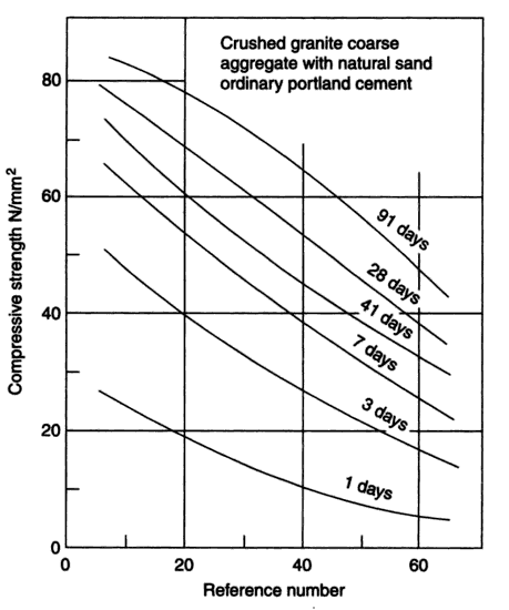 | Figure 2.1. Relation between compressive strength and reference number (RN) for crushed coarse aggregate using ordinary Portland cement (Source: Ref [4] Erntroy and Shacklock, 1954) |
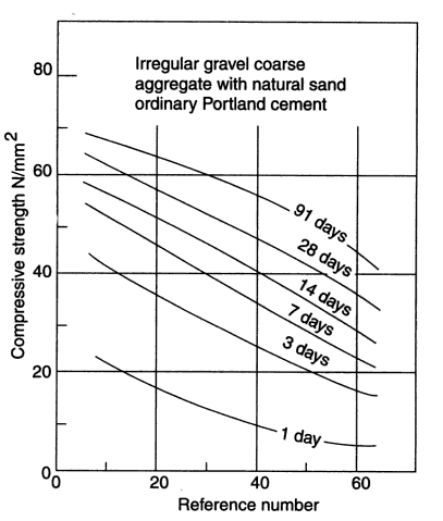 | Figure 2.2. Relation between compressive strength and reference number (RN) for irregular gravel coarse aggregate using ordinary Portland cement (Source: Ref [4]) |
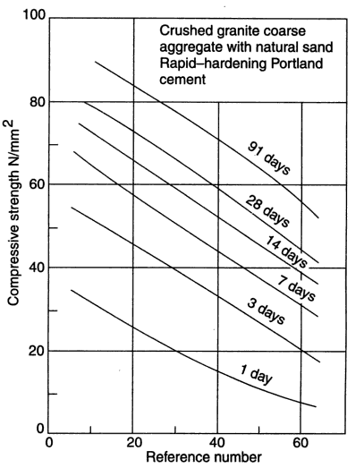 | Figure 2.3. Relation between compressive strength and reference number (RN) for crushed granite coarse aggregate using Rapid hardening Portland cement (Source: Ref [4]) |
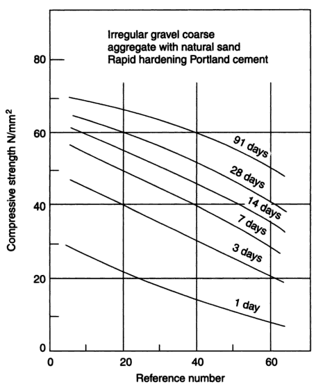 | Figure 2.4. Relation between compressive strength and reference number (RN) for irregular gravel coarse aggregate using Rapid hardening cement (Source: Ref [4]) |
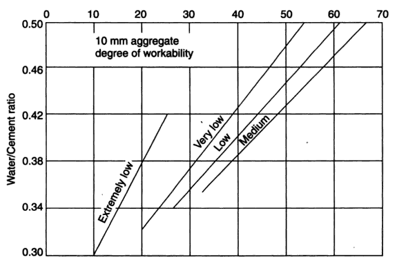 | Figure 2.5. The relation between water cement (wc) ratio and the reference number (RN) for 10mm maximum size aggregate: (Source: Ref [4]) |
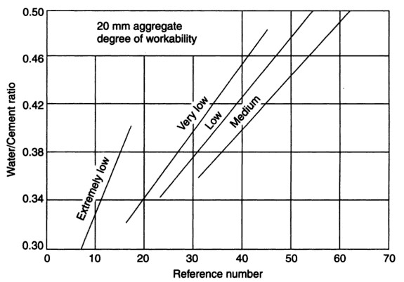 | Figure 2.6. The relation between water cement (wc) ratio and the reference number (RN) for 20mm maximum size aggregate (Source: Ref [4]) |
The relation between the aggregate-cement (ac) and water-cement (wc) ratios to achieve the desired degree or level of workability with a given type and maximum size of aggregate are compiled in Tables 2.1 and 2.2 for two different types of cements. Further, according to Raina [4], the design tables are obtained with aggregate containing 30 percent of the material passing the 4.75 mm sieve. Thus, if other ingredients are used suitable adjustments have to be made accordingly. Aggregate available at site may be suitably combined by the graphical method to satisfy the above requirement. In view of the considerable variations in the properties of aggregate, it is recommended that trial mixes must first be made and then suitable adjustments in grading and mix proportions effected to achieve the desired results [13].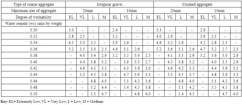 | Table 2.1. Aggregate cement ratio (by weight) required to give four levels of workability with different water –cement (wc) ratios using ordinary Portland cement (Source: [4] Erntroy and Shacklock, 1954) |
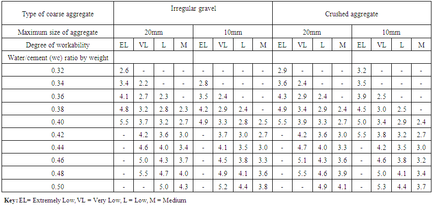 | Table 2.2. Aggregate cement ratio (by weight) required to give four degrees of workability with different water –cement (WC) ratios using rapid hardening cement (Source: Ref [4]) |
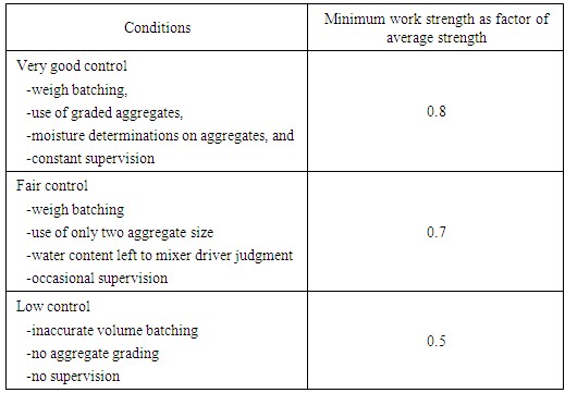
2.3.5.2. Mix Design ProcedureIn order to arrive at the required mix proportions using Erntroy and Shacklock [4] empirical graphs, Raina [13] highlighted eight steps. The procedure involves a series of estimations and calculations based on the empirical graphs and tabular data presented as follows;Step 1Maximum size of Coarse aggregates and individual grading of both Fine aggregates (FA) and Coarse aggregates (CA);Identify the maximum size of Coarse aggregate to be used (normally 20 mm for high strength concrete mixes).Create the Grading of representative samples of Fine aggregates and Coarse aggregates to be used.Step 2Average Strength;From the conditions of quality control expected to be exercised, and the specified minimum works cube crushing strength at the specified age, estimate the average cube strength at that age, using Table 2.3. In case the concrete strength is determined in terms of cylinder strength, then the corresponding cube strength may be taken as 1.22 times the corresponding cylinder strength.)Table 2.3. Control factor for different conditions (Source: Raina, 2009)
 |
| |
|
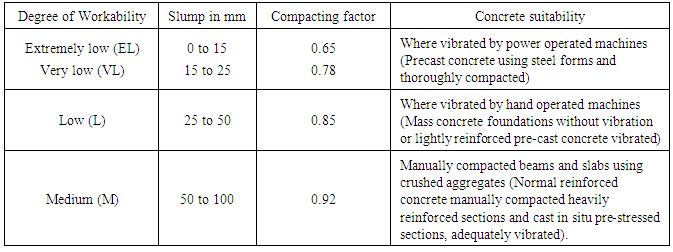
Table 2.4. Uses of concrete of different degree of workability (Source: Raina, 2009)
 |
| |
|
Step 3Reference Number (RN);Depending upon whether the cement to be used is Ordinary Portland Cement (OPC) or Rapid Hardening Portland Cement (RHPC), and whether the coarse aggregate to be used is crushed stone or irregular (natural) gravel, read off the Reference Number for the average compressive strength at the specified age (days) from Figures. 4.1 to 4.4.Step 4Water-Cement ratio (WC)Read off the value of water/cement (wc) ratio (by weight) against the value of the Reference Number (RN) for the chosen degree of workability and the maximum size of coarse aggregate.Step 5Aggregate/Cement ratio (ac);Read the value of (combined) Aggregate/cement (ac) ratio for the specific values of water-cement (wc) ratio and the level of 'workability' (depending on the type of cement, OPC or RHPC) for the selected type of CA - irregular gravel or crushed stone, and for the selected maximum size of CA 20 mm or 10 mm.Step 6Proportion of FA in the Combined Aggregate;Proceed by the graphical method using the individual gradings of the FA and CA established in Step 1, establish the percentage proportion of FA in the combined aggregate such that 30 per cent of the combined aggregate passes 4.75 mm sieve.Step 7Proportions of the first Trial Mix;The aggregate cement (ac) ratio (for easy workability) and the water-cement (wc) ratio are established from steps 4 and 5. Knowing the ratios of water-cement and aggregate cement, and FA to total aggregate, and the specific gravities of ingredients of the mix, the cement content is calculated using the volume (absolute) method. Step 8Final Mix;Having empirically established the proportions for the first trial mix, a number of trial mixes should then be made with slight alterations in the proportions for strength and workability, and these should be tested in order to finalise the exact proportions of the mix to be finally adopted.
2.4. Computer Aided Concrete Mix Design
Research scientists develop computer programs for concrete mix design, and they have proved to be accurate, time saving and significantly error free when compared to manual hand calculations.
2.4.1. Spreadsheet Programs
Spreadsheets are most commonly used in civil engineering designs. There are many spreadsheets developed by different users for different designs including concrete mix design. For instance, Ganju [14] used spreadsheet alternative to develop a design method for trial mixes by direct computing the ingredients. In his research the results obtained were in agreement with experimental and manual calculations [14]. In 1995, Kasperkiewicz designed a spreadsheet program in Microsoft excel for Optimization of Concrete Mix designs, His spreadsheet focused on obtaining accurate mix proportions at optimum costs using linear programming equations [15].
2.4.2. Spreadsheet Programs Errors
Many researchers have developed spreadsheet for concrete mix design but recent researches have shown that spreadsheets can be subjeced to errors. Such researches were conducted by Brown and Gould in 1987 [16], and in 1997, Teo and Tan performed an experiment to determine the frequency of errors by using a spreadsheet [17] and a related study by Panko [18] on the range of errors.On the same issue, a report by IBM shows some common causes of errors when using Ms Excel spreadsheet program [19] which include; mistakes in logic; incorrectly copied formulas; accidentally overwritten formulas; misuse of built-in function; omitted factors; data input errors.
2.4.3. Developed Mix Design using MATLAB
Abdulahi et al [1] developed an ‘m-file’ in MATLAB and in their research, they concluded that using an ‘m-file’ developed in MATLAB gave the same results and reliable than using hand calculations. The scholars compared results by the ‘m-file’ named LWC and those by hand in two cases and the results were the same or very close.Zealakshmi et al. [2] developed a program in MATLAB to design a concrete mix for high strength concrete. In their research they concluded that the results were accurate and very close to hand calculations and time saving than hand calculations. Gupta [3] developed a concrete mix design programm using MATLAB and tested the results in laboratory. The research concluded that the results by using the program were accurate as they adhere to manual calculations and laboratory results.
3. Methodology
The methodology of the present research is based on successful development of a MATLAB based mix design program involving a series of techniques which required interpretation, conversion and making assumptions based on the Erntroy and Shacklock [4] empirical graphs. The steps and techniques are highlighted [4] as follows;Step 1: Coding environmentMATLAB, an advanced mathematical computing language was used to develop the program. The program was coded, and tested using MATLAB 2013b v8.2, a series of preliminary codes was developed before arriving to the ultimate satisfying program.Step 2: Interpretation of Empirical graphs and tabular dataThe Empirical graphs and tabular data from Erntroy and Shacklock (1954) were interpreted and converted into their respective modal equations by linear regression methods [4].Step 3: Development of AlgorithmAn algorithm based on procedures highlighted by Erntroy and Shacklock (1954) was then developed to assist the development of MATLAB code. A summary showing the procedures required in the mix design is shown in Figure 3.1 [4].Step 4: Development of MATLAB codeThe developed algorithm was then converted into the respective MATLAB code using different conditional statements.Step 5: Development of Graphical user interfaceA simple graphical user interface was developed in MATLAB GUIDE for easy use and the interface code was tested for errors before adopting it.Step 6: Debugging the programThis step involved checking for and correcting of errors, this was done on each stage of the program development to ensure there are no errors to interfere with the program operations.Step 7: Testing the programAfter successful checking and correcting errors on the program, the program was tested using reputable examples. Then the results from manual computations and those obtained from the program were compared.Step 8: Publishing the programAfter successful testing of the program it was published using MATLAB compiler to enable it to be distributed to other machines.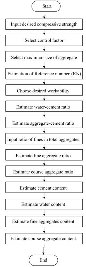 | Figure 3.1. Program Algorithm |
4. Detailed Design
4.1. Design Program
This research dealt with the design of high strength concrete (HSC) mixes using MATLAB. The design program was done by using MATHWORKS MATLAB 2011b v7.12 followed by subsequent debugging and testing. The program is designed for use with Ordinary Portland cement and crushed aggregate, and it can design concrete of strengths greater than 60MPa.
4.2. Assumptions for the Design
In design process, assumptions are essential in all engineering solutions. In this research, a number of assumptions (below) related to the design approach were made and adopted by the authors in order to develop the program;Ÿ Coarse aggregate are crushedŸ Cement used is ordinary Portland cementŸ Concrete strength expected at age of 28 daysŸ Concrete strength is tested in cubesŸ Mixing conditions are standardŸ Mix materials do not contain impurities.
4.3. Development of Equations from Empirical Graphs
The empirical graphs developed by Erntroy and Shacklock [4] were converted into their respective equations using linear regression. The required graphs were;(i) Relation between compressive strength (CS) and reference number (RN).(ii) Relation between water-cement ratio and Reference number for 20mm and 10mm maximum aggregates.(iii) Relation between water-cement (wc) ratio and aggregate-cement (ac) ratio for 20mm and 10mm maximum aggregate sizes.All of the predicted equations were linear, and linear regression method was used to derive them.The general formula for the equations which are described in the next section is given equation 4.1. | (4.1) |
Where;“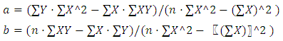 ”The obtained linear equations were then plotted in the same graph as the original data extracted from Erntroy and Shacklock [4] equations in solid and dotted linear equation lines.
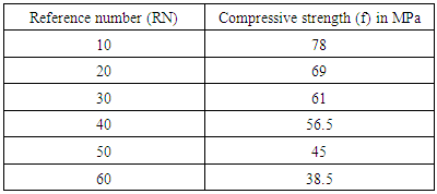
4.3.1. Reference Number (RN) vs Compressive Strength
The relation between compressive strength at the age of 28 days and reference number (RN) for ordinary Portland cement, and by using aggregates containing crushed granite coarse aggregate with natural sand, was obtained using linear regression analysis by converting data from Erntroy and Shacklock [4] graph from Figure 2.1 as shown in Table 4.1.Table 4.1. Relation between reference number (RN) and compressive strength using Ordinary Portland cement (Source: Ref [4] Erntroy and Shacklock, 1954)
 |
| |
|
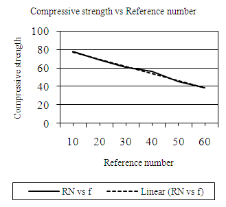 | Figure 4.1. Relationship between compressive strength and reference number (RN) |
The linear equation was obtained using equation 4.1 as given in the previous section. Equation 4.2 was obtained and then plotted in Figure 4.1 in dotted lines in a compound graph together with the original data in Table 4.1. | (4.2) |
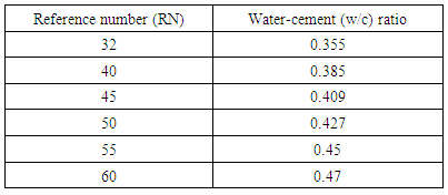
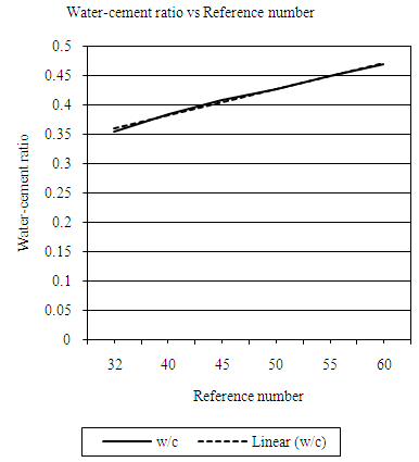
4.3.2. Water-cement (wc) Ratio vs Reference Number (RN)
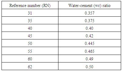
The equations representing the relationship between water-cement (wc) ratio and Reference number (RN) were obtained for maximum aggregate sizes of 10mm and 20mm respectively for each desired workability.4.3.2.1. Using 20mm AggregatesFigure 2.6 represents the Erntroy and Shacklock [4] graph showing the relationship between water-cement (wc) ratio and reference number (RN) when 20mm coarse aggregates are used in the concrete mix. Data from these graphs were extracted and their respective linear modal equations developed for desired workability in each case as described in the following sections. 4.3.2.1.1. Extremely Low WorkabilityTable 4.2 represents data extracted from Erntroy and Shacklock [4] graphs as shown in Figure 2.6 which was used to develop modal equation for relationship between water-cement (wc) ratio and reference number (RN) for extremely low workability.Table 4.2. Relation between Reference number (RN) and water-cement (w/c) ratio (20mm aggregate, ELW) (Source: Ref [4])
 |
| |
|
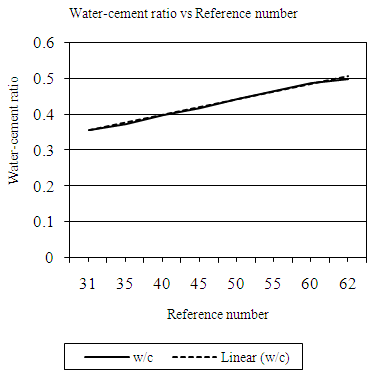
 | Figure 4.2. Relation between Reference number (RN) and water-cement (wc) ratio (20mm aggregate, ELW) |
Equation 4.3 represents the linear relationship between water-cement (wc) ratio and reference number (RN) for desired workability which is ‘extremely low’ using 20mm aggregates as developed by the authors. Figure 4.2 represents a compound graph comprising of Equation 4.3 and data from Table 4.2. | (4.3) |
4.3.2.1.2. Very Low WorkabilityTable 4.3 represents data extracted from Erntroy and Shacklock [4] graphs as shown in Figure 2.6 which was used to develop modal equation for relationship between water-cement (wc) ratio and reference number (RN) for very low workability.Table 4.3. Relation between Reference number (RN) and water-cement (wc) ratio (20mm aggregates, VLW) (Source: Ref [4])
 |
| |
|
 | Figure 4.3. Relation between water-cement (wc) ratio and reference number (RN) (20mm aggregates, VLW) |
Equation 4.4 represents the linear relationship between water-cement (wc) ratio and reference number (RN) for desired workability which is ‘very low’ using 20mm aggregates as developed by the author. Figure 4.3 represents a compound graph comprising of Equation 4.4 and data from Table 4.3. | (4.4) |
4.3.2.1.3. Low WorkabilityTable 4.4 represents data extracted from Erntroy and Shacklock [4] graphs as shown in Figure 2.6 which was used to develop modal equation for relationship between water-cement (wc) ratio and reference number (RN) for low workability.Table 4.4. Relation between Reference number (RN) and water-cement (wc) ratio (20mm aggregates, LW) (Source: Ref [4])
 |
| |
|
 | Figure 4.4. Relation between water-cement (w/c) ratio and reference number (20mm aggregates, LW) |
Equation 4.5 represents the linear relationship between water-cement (wc) ratio and reference number (RN) for desired workability which is ‘low’ using 20mm aggregates as developed by the authors. Figure 4.4 represents a compound graph comprising of Equation 4.5 and data from Table 4.4. | (4.5) |
4.3.2.1.4. Medium WorkabilityTable 4.5 represents data extracted from Erntroy and Shacklock [4] graphs as shown in Figure 2.6 which was used to develop modal equation for relationship between water-cement (wc) ratio and reference number (RN) for medium workability.Table 4.5. Relation between Reference number (RN) and water-cement (wc) ratio (20mm aggregates, MW) (Source: Ref [4])
 |
| |
|
 | Figure 4.5. Relation between water cement (wc) ratio and reference number (RN) (20mm aggregates, MW) |
Equation 4.6 represents the linear relationship between water-cement (wc) ratio and reference number (RN) for desired workability which is ‘medium’ using 20mm aggregates as developed by the authors. Figure 4.5 represents a compound graph comprising of Equation 4.6 and data from Table 4.5. | (4.6) |
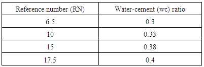
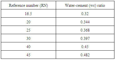
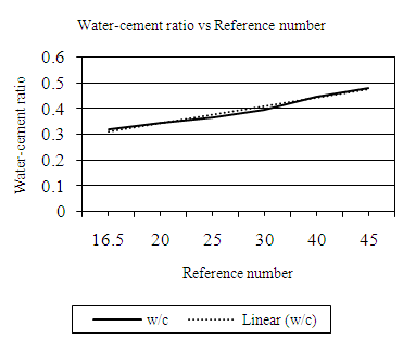
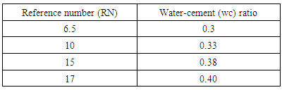
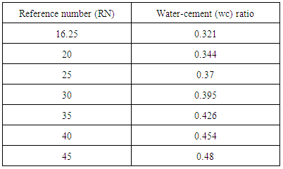
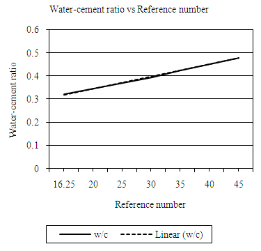
4.3.2.2. Using 10mm AggregatesFigure 2.5 represents the Erntroy and Shacklock [4] graph showing the relationship between water-cement (wc) ratio and reference number (RN) when 10mm coarse aggregates are used in the concrete mix. Data from these graphs were extracted and their respective linear modal equations developed for opted workability as explained in the following sections. 4.3.2.2.1. Extremely Low WorkabilityTable 4.6 represents data extracted from Erntroy and Shacklock [4] graphs as shown in Figure 2.5 which was used to develop modal equation for relationship between water-cement (wc) ratio and reference number (RN) for extremely low workability.Table 4.6. Relation between Reference number (RN) and water-cement (wc) ratio (ELW, 10mm aggregate) (Source: Ref [4])
 |
| |
|
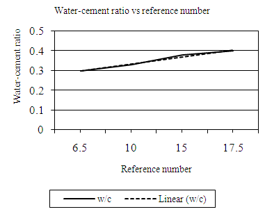
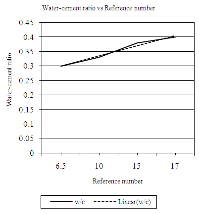 | Figure 4.6. Relation between water-cement (wc) ratio and reference number (RN) (ELW, 10mm aggregate) |
Equation 4.7 represents the linear relationship between water-cement (wc) ratio and reference number (RN) for opted workability which is ‘extremely low’ using 10mm aggregates as developed by the authors. Figure 4.6 represents a compound graph comprising of Equation 4.7 and data from Table 4.6. | (4.7) |
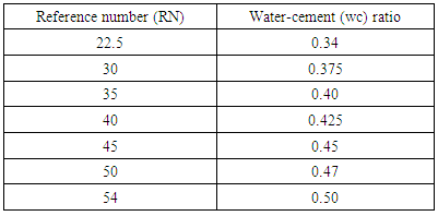
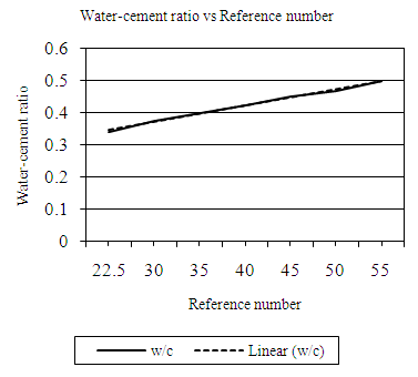
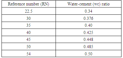
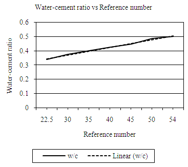
4.3.2.2.2. Very Low WorkabilityTable 4.7 represents data extracted from Erntroy and Shacklock [4] graphs as shown in Figure 2.5 which was used to develop modal equation for relationship between water-cement (wc) ratio and reference number (RN) for very low workability.Table 4.7. Relation between Reference number (RN) and water-cement (wc) ratio (VLW, 10mm aggregate) (Source: Ref [4])
 |
| |
|
 | Figure 4.7. Relation between water-cement (wc) ratio and reference number (RN) (VLW, 10mm aggregate) |
Equation 4.8 represents the linear relationship between water-cement (wc) ratio and reference number (RN) for desired workability which is ‘very low’ using 10mm. Figure 4.7 represents a compound graph comprising of Equation 4.8 and data from Table 4.7. | (4.8) |
4.3.2.2.3. Low WorkabilityTable 4.8 represents data extracted from Erntroy and Shacklock [4] graphs as shown in Figure 2.5 which was used to develop modal equation for relationship between water-cement (wc) ratio and reference number (RN) for low workability.Table 4.8. Relation between Reference number (RN) and water-cement (wc) ratio (LW, 10mm aggregate) (Source: Ref [4])
 |
| |
|
 | Figure 4.8. Relation between water-cement (wc) ratio and reference number (RN) (LW, 10mm aggregate) |
Equation 4.9 represents the linear relationship between water-cement ratio and reference number for desired workability which is ‘low’ using 10mm aggregates. Figure 4.8 represents a compound graph comprising of Equation 4.9 and data from Table 4.8. | (4.9) |
4.3.2.2.4. Medium WorkabilityTable 4.9 represents data extracted from Erntroy and Shacklock [4] graphs as shown in Figure 2.5 which was used to develop modal equation for relationship between water-cement (wc) ratio and reference number (RN) for medium workability.Table 4.9. Relation between Reference number (RN) and water-cement (wc) ratio (MW, 10mm aggregate) (Source: Ref [4])
 |
| |
|
 | Figure 4.9. Relation between water-cement (wc) ratio and reference number (RN) (M, 10mm aggregate) |
Equation 4.10 represents the linear relationship between water-cement (wc) ratio and reference number (RN) for desired workability ‘medium’ using 10mm aggregates. Figure 4.9 represents a compound graph comprising of Equation 4.10 and data from Table 4.9. | (4.10) |
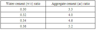
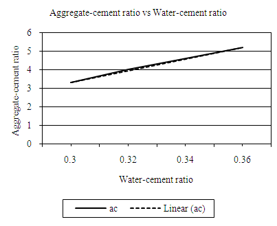
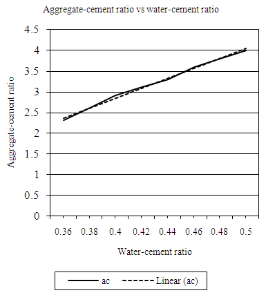
4.3.3. Aggregate Cement Ratio and Water Cement Ratio
The equations representing the relationship between water-cement (wc) ratio and aggregate cement (ac) ratio were then obtained for maximum aggregate sizes of 10mm and 20mm respectively for each desired workability and are described in the following section. For each equation water cement ratio is termed ‘wc’, and aggregate cement ratio is termed ‘ac’.4.3.3.1. Using 20mm AggregatesTable 2.1 contains aggregate cement ratios (by weight) required to come out with four levels of workability with different water-cement (wc) ratios using ordinary Portland cement (OPC). Data from this table was plotted and the resulting graphs used to develop modal linear equations for the relationship between water-cement (wc) ratio and aggregate-cement (ac) ratio. 4.3.3.1.1. Extremely Low WorkabilityTable 4.10 represents data extracted from Erntroy and Shacklock [4] tables as shown in Table 2.1 which was used to develop modal equation for relationship between water-cement (wc) ratio and aggregate-cement (ac) ratio for extremely low workability.Table 4.10. Relation between water-cement (wc) ratio and aggregate-cement (ac) ratio (ELW, 20mm aggregate) (Source: Ref [4])
 |
| |
|
 | Figure 4.10. Relation between water -cement (wc) ratio and aggregate-cement (ac) ratio (ELW, 20mm aggregate) |
Equation 4.11 represents the linear relationship between water-cement (wc) ratio and aggregate-cement (ac) ratio for opted workability which is ‘extremely low’ using 20mm course aggregates. Figure 4.10 represents a compound graph comprising of Equation 4.11 and data from Table 4.10. | (4.11) |
4.3.3.1.2. Very Low WorkabilityTable 4.11 represents data extracted from Erntroy and Shacklock [4] tables as shown in Table 2.1 which was used to develop modal equation for relationship between water-cement (wc) ratio and aggregate-cement (ac) ratio for very low workability.Table 4.11. Relation between water-cement (wc) ratio and aggregate-cement (ac) ratio (VLW, 20mm aggregate) (Source: Ref [4])
 |
| |
|
 | Figure 4.11. Relation between water-cement (wc) ratio and aggregate-cement ratio (VLW, 20mm aggregate) |
Equation 4.12 represents the linear relationship between water-cement (wc) ratio and aggregate-cement (ac) ratio for opted workability which is ‘very low’ using 20mm coarse aggregates. Figure 4.11 represents a compound graph comprising of Equation 4.12 and data from Table 4.11. | (4.12) |
4.3.3.1.3. Low WorkabilityTable 4.12 represents data extracted from Erntroy and Shacklock [4] tables as shown in Table 2.1 which was used to develop modal equation for relationship between water-cement (wc) ratio and aggregate-cement (ac) ratio for low workability.Table 4.12. Relation between water-cement (wc) ratio and aggregate-cement (ac) ratio (LW, 20mm aggregate) (Source: Ref [4])
 |
| |
|
 | Figure 4.12. Relation between water (wc) cement ratio and aggregate-cement (ac) ratio (LW, 20mm aggregate) |
Equation 4.13 represents the linear relationship between water-cement (wc) ratio and aggregate-cement (ac) ratio for desired workability which is ‘low’ using 20mm course aggregates. Figure 4.12 represents a compound graph comprising of Equation 4.13 and data from Table 4.12. | (4.13) |
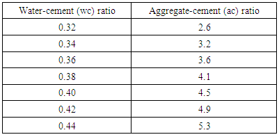
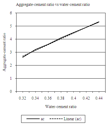
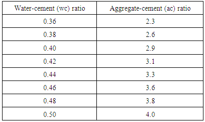
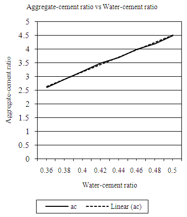
4.3.3.1.4. Medium WorkabilityTable 4.13 represents data extracted from Erntroy and Shacklock [4] tables as shown in Table 2.1 which was used to develop modal equation for relationship between water-cement (wc) ratio and aggregate-cement (ac) ratio for medium workability.Table 4.13. Relation between water cement (wc) ratio and aggregate-cement (ac) ratio (MW, 20mm aggregate) (Source: Ref [4])
 |
| |
|
 | Figure 4.13. Relation between water-cement (wc) ratio and aggregate-cement (ac) ratio (MW, 20mm aggregate) |
Equation 4.14 represents the linear relationship between water-cement (wc) ratio and aggregate-cement (ac) ratio for desired workability which is ‘medium’ using 20mm course aggregates. Figure 4.13 represents a compound graph comprising of Equation 4.14 and data from Table 4.13. | (4.14) |
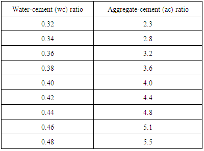
4.3.3.2. Using 10mm aggregatesTable 2.1 contains aggregate cement ratios (by weight) required to come out with four levels of workability with different water-cement (wc) ratios using ordinary Portland cement. Data from this table was plotted and the resulting graphs used to develop modal linear equations for the relationship between water-cement (wc) ratio and aggregate-cement (ac) ratio. 4.3.3.2.1. Extremely Low WorkabilityTable 4.14 represents data extracted from Erntroy and Shacklock [4] tables as shown in Table 2.1 which was used to develop modal equation for relationship between water-cement (wc) ratio and aggregate-cement (ac) ratio for extremely low workability.Table 4.14. Relation between water-cement (wc) ratio and aggregate-cement (ac) ratio (ELW, 10mm aggregate) (Source: Ref [4])
 |
| |
|
 | Figure 4.14. Relation between water-cement (wc) ratio and aggregate-cement ratio (ELW, 10mm aggregate) |
Equation 4.15 represents the linear relationship between water-cement (wc) ratio and aggregate-cement ac) ratio for desired workability which is ‘extremely low’ using 10mm course aggregates. Figure 4.14 represents a compound graph comprising of Equation 4.15 and data from Table 4.14. | (4.15) |
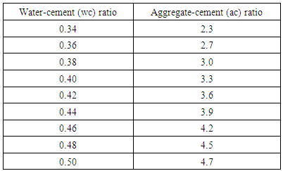
4.3.3.2.2. Very Low WorkabilityTable 4.15 represents data extracted from Erntroy and Shacklock [4] tables as shown in Table 2.1 which was used to develop modal equation for relationship between water-cement (wc) ratio and aggregate-cement (ac) ratio for very low workability.Table 4.15. Relation between water-cement (wc) ratio and aggregate-cement (ac) ratio (VLW, 10mm aggregate) (Source: Ref [4])
 |
| |
|
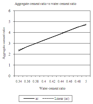
 | Figure 4.15. Relation between water-cement (wc) ratio and aggregate-cement ratio (VLW, 10mm aggregate) |
Equation 4.16 represents the linear relationship between water-cement (wc) ratio and aggregate-cement (ac) ratio for opted workability which is ‘very low’ using 10mm coarse aggregates. Figure 4.15 represents a compound graph comprising of Equation 4.16 and data from Table 4.15. | (4.16) |
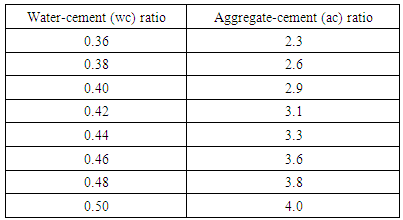
4.3.3.2.3. Low WorkabilityTable 4.16 represents data extracted from Erntroy and Shacklock [4] tables as shown in Table 2.1 which was used to develop a modal equation for relationship between water-cement (wc) ratio and aggregate-cement (ac) ratio for low workability.Table 4.16. Relation between water-cement (wc) ratio and aggregate-cement (ac) ratio (LW, 10mm aggregate) (Source: Ref [4])
 |
| |
|
 | Figure 4.16. Relation between water-cement (wc) ratio and aggregate-cement ratio (LW, 10mm aggregate) |
Equation 4.17 represents the linear relationship between water-cement (wc) ratio and aggregate-cement (ac) ratio for opted workability which is ‘low’ using 10mm coarse aggregates. Figure 4.16 represents a compound graph comprising of Equation 4.17 and data from Table 4.16. | (4.17) |
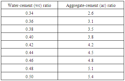
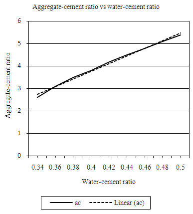
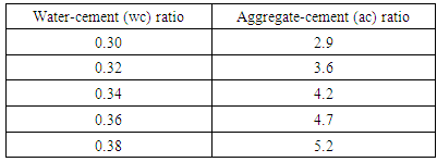
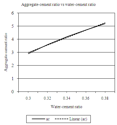
4.3.3.2.4. Medium WorkabilityTable 4.17 represents data extracted from Erntroy and Shacklock [4] tables as shown in Table 2.1 which was used to develop a modal equation for relationship between water-cement (wc) ratio and aggregate-cement (ac) ratio for medium workability.Table 4.17. Relation between water-cement (wc) ratio and aggregate-cement ratio (MW, 10mm aggregate) (Source: Ref [4])
 |
| |
|
 | Figure 4.17. Relation between water-cement (wc) ratio and aggregate-cement ratio (MW, 10mm aggregate) |
Equation 4.18 represents the linear relationship between water-cement (wc) ratio and aggregate-cement (ac) ratio for desired workability which is ‘medium’ using 10mm coarse aggregates. Figure 4.17 represents a compound graph comprising of Equation 4.18 and data from Table 4.17. | (4.18) |
4.4. Development of Algorithm
The procedures highlighted in Section Three (3) were converted into a proper algorithm which was then used in program development (Figure 3.1) [20].
4.5. Program Input and Output
The program requires inputs in order to arrive at the required output as described in the following section.
4.5.1. Input
Upon operating the program, the user will be required to specify the following details;i. Maximum aggregate size (10mm or 20mm).ii. Desired 28 days compressive strengthiii. Desired workability of the concrete specimen by choosing the right option;iv. Percentage of entrained air.v. Percentage of fines on aggregates when 30% of aggregates pass through a 4.75 mm sieve.vi. Specific gravities of;a. Cement.b. Course aggregates.c. Fine aggregates.d. Water.
4.5.2. Output
Upon commanding the calculations from the program’s user interface, the following outputs are delivered by the program:i. Mix proportions;a. Water-cement ratiob. Fine aggregates cement ratioc. Course aggregate cement ratio.ii. Mixture content in kg in 1.0 m3 of concrete;a. Cement content.b. Fine aggregate content.c. Coarse aggregate content.d. Water content.
4.6. Development of a MATLAB Code
The developed algorithm was then converted into MATLAB code to create a script ‘m-file’ which is the main file containing all scripts and functions for the designed program. The script’s codes were double checked and tested to ensure the algorithm is well performed and the functions are coded properly.
4.7. Debugging of the Code
Debugging involves checking for errors in a computer program code that, might lead to errors in program execution and then correcting them. The developed ‘m-file’ was checked for errors in in-built functions, and user made functions and was found error-free and hence, the ‘m-file’ was finally properly coded.
4.8. User Interface
The program’s user interface was developed to be simple and easy to be used by any person. The user interface was developed using MATLAB’S GUIDE v2.5 add-on. The interface is divided into two sections:i. The Input section which has two panels where the user is supposed to input the required data.ii. The output section which displays results when the calculate Button is pressed.The ou.2tput section is further subdivided into mix proportions and mix contents for a 1 m3 concrete. iii. Other additions includes:a. Print button which enables the user to print a screenshot of the program results.b. Assumptions panel which displays assumptions adopted to develop the program.
4.9. Operating the Program
Operating the program has been designed in a simple way. The user is required to log in (input) the required parameters and then press calculate, the program will then generate the required mix proportions and the corresponding weights for a 1.0 m3 of concrete.
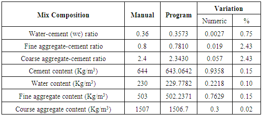
4.10. Testing the Program
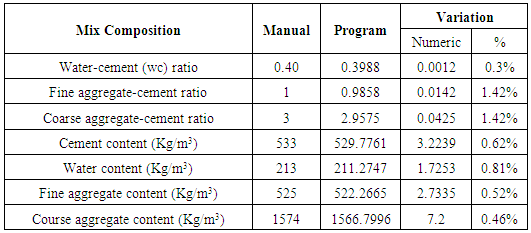
The program was tested using two different theoretical problems and the results compared with a manual method. The results of specific problems obtained by hand calculations and using the program are presented in Table 4.18 and Table 4.19.
4.11. Discussion
The values obtained by the developed program are very close to those obtained by manual calculations in Table 4.18 and Table 4.19 and are illustrated in Figure 4.18 and Figure 4.19 from previous section. And the program results are in agreement with those done by manual calculations. By using the program, it is possible to avoid human errors related to manual approach in mix design. Further, the required outputs are consistent, efficient and reliable.Table 4.18. Mix design results for problem One (1)
 |
| |
|
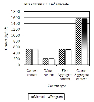 | Figure 4.18. Presentation of mix design results for problem One (1) |
Table 4.19. Mix design results for problem Two (2)
 |
| |
|
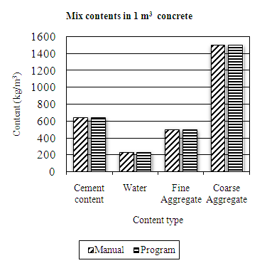 | Figure 4.19. Presentation of mix design results for problem Two (2) |
It can be noted that, the results from the program are having lower values (compared to manual method), since the program gives exact values rather than estimating (round-up) as normally done by a human being. In fact, human proficiency cannot be guaranteed especially under varied conditions.The program can design concrete of strengths greater than 60MPa. And even though the program was initially designed for high strength concrete mixes, it can also be used to design normal mixes, but with limits to medium workability only. The need for faster and accurate design approaches is a priority to any civil/structural engineer. The design software program developed in the present work could be useful to engineering professionals in the construction industry, both as a design tool; and academic-oriented support tool in research institutions, without a need for crucial pre-training.
5. Conclusions
A MATLAB based program has been developed and compiled to run as standalone application using several conditional statements, different equations/models were developed from Erntroy and Shacklock’s [4] empirical graphs and then inserted in their appropriate section in the program code and algorithm. The program has been tested using two textural examples and has shown significant ability to design high strength concrete (HSC) at a very short period. The program can design mixes above 60MPa of concrete strength. It can also be used for normal strength concretes in the case when lower workability is opted. The output results of the calculations by the program include the water cement (wc) ratio, fine aggregates cement ratio (FAc), coarse aggregate (CAC) cement ratio, both cement content and water content, weight of fine aggregates and last, weight coarse aggregates in 1.0 m3 of concrete.The values obtained by the program are very close to those obtained by manual calculations (Tables 4.18 and 4.19) and presented in Figures 4.18 and 4.19. From the results, it is evident that the program works as the values obtained match closely with those computed by manual calculations.The results from the design program are lower since the program gives exact values rather than estimating as done by a human being. From the study, it was established that even though the program was initially designed for high strength concrete mixes, it can also design normal mixes but only limited to medium workability. Besides, the program can design concrete of strengths greater than 60MPa.The program has been developed with a simple user interface to enable anyone to use it without any need of expertise in programming. Based on the values obtained by using the program, the end obtained results are similar and very close to those obtained by manual calculations (as presented in tables 4.18 and 4.19 and illustrated in Figures 4.17 and 4.18).
ACKNOWLEGEMENTS
The authors wish to thank all those who in a way supported this research and finally accomplishing it successfully. Special thanks goes to the authors whose early research works on HSC has been useful sources and inspiration to conduct this research.
References
| [1] | Abdullahi, M., Al-Mattarneh, H. M. A., Mohammed, B. S. and Sadiku, S., 2011. m-file for mix design of structural lightweight concrete using developed models. Journal of Engineering Science and Technology, pp. 520-531. |
| [2] | Zealakshmi, D., Ravichandran, A. and Kothandaraman, S., 2013. Computer Aided High Strength Concrete Mixture Proportion using Mat Lab. International Journal of Computer Applications, pp. 18-25. |
| [3] | Gupta, A., Mittal, N. and Saini, B., 2011. Computer-aided Proportioning of Concrete Mixes, Delhi: National Institute of Technology India. |
| [4] | Erntroy, H. C. and Shacklock, B. W., 1954. Design of High-strength Concrete Mixes. s.l.:Cement and Concrete Association. |
| [5] | Newman, J. and Choo, B. S., 2003. Advanced Concrete Technology 3: Processes. s.l.:Butterworth-Heinemann. |
| [6] | Caldarone, M. A., 2008. High-Strength Concrete: A Practical Guide. s.l.:CRC PRESS. |
| [7] | Charlett, A. J., 2007. Fundamental Building Technology. New York: Taylor and Francis. |
| [8] | Mehta, P. and Aitcin, P., 1990. Principles Underlying Production of High-Performance. Cement, Concrete, and Aggregates, pp. 70-78. |
| [9] | Malier, Y., 1992. High Performance Concrete: From material to structure. s.l.:CRC Press. |
| [10] | BSI, 2002. BS 8500:2. London: s.n. |
| [11] | Shetty, M., 2000. Concrete technology: Theory and practice. Chand and Company LTD. |
| [12] | BRE-Building Research Establishment, 1997. Design of normal concrete mixes. London: Construction Research Communications. |
| [13] | Raina, D. V., 2009. Raina's field manual for highway and bridge engineers. 3rd ed. Mumbai: Shroff Publishers & Distributors Pvt. Ltd. |
| [14] | Ganju, T., 1996. Spread sheeting mix designs. ACI: Concrete International, 18(12), pp. 35-38. |
| [15] | Kasperkiewicz, J., 1995. Optimization of Concrete Mix Using a Spreadsheet Package. ACI:Materials Journal, 91(6), pp. 551-559. |
| [16] | Brown, P. and Gould, J., 1987. An experimental study of people creating spreadsheets. ACM Transactions on Office Information Systems, Issue Vol.5, pp. 258-272. |
| [17] | Teo, T. and Tan, M., 1997. Quantitative and qualitative errors in spreadsheet development. s.l., s.n., pp. 149-155. |
| [18] | Panko Ray, P., n.d. University of Hawaii, s.l.: www.panko.cba.hawaii.edu/ssr. |
| [19] | IBM Corporation, 2010. The Risks of Using Spreadsheets for statistical analysis, New York: IBM Corporation. |
| [20] | http://www.mathworks.com/matlabcentral/fileexchange/64220 (Program Link). |

 Abstract
 Reference
 Full-Text PDF
 Full-text HTML