-
Paper Information
- Next Paper
- Previous Paper
- Paper Submission
-
Journal Information
- About This Journal
- Editorial Board
- Current Issue
- Archive
- Author Guidelines
- Contact Us
Journal of Civil Engineering Research
p-ISSN: 2163-2316 e-ISSN: 2163-2340
2017; 7(2): 63-66
doi:10.5923/j.jce.20170702.05

Modeling and Finite Element Analysis of the Hydraulic Buffer in Elevator Systems
 Abstract
 Reference
 Full-Text PDF
 Full-text HTML
Ruoting Li, Gongfa Chen, Peng Liang
School of Civil and Transportation Engineering, Guangdong University of Technology, Guangzhou, China
Correspondence to: Gongfa Chen, School of Civil and Transportation Engineering, Guangdong University of Technology, Guangzhou, China.
| Email: |  |
Copyright © 2017 Scientific & Academic Publishing. All Rights Reserved.
This work is licensed under the Creative Commons Attribution International License (CC BY).
http://creativecommons.org/licenses/by/4.0/

Hydraulic buffers are safety protection devices for elevators beyond the limit position. The hydraulic buffer prevents the downward motion of the elevator, which impacts it, by absorbing the kinetic energy of the elevator carriage. A simplified modeling method has been proposed in this article for the finite element (FE) analysis in the case of elevator falling to the pit bottom. According to the structural properties and dynamic mechanism of the hydraulic buffer, a mathematical model has been established to represent the buffering process. Based on a nonlinear relationship between the pressure and velocity, which is simulated via MATLAB, a simplified model for the hydraulic buffer is established using connector element in ABAQUS. The curves of the acceleration and velocity as a function of time during buffering are obtained by using a simplified FE impact model to analyze the elevator falling to the pit bottom. Finally, the whole FE analysis has been conducted for the elevator falling to the pit bottom by imposing the loading in the form of the acceleration-time curve. The results obtained in the article show that: firstly, the acceleration-time and velocity-time curves obtained by the simplified FE impact model match well with those obtained by the mathematical model and experimental tests; secondly, the bottom beam of the elevator carriage absorbs the kinetic energy and incurs the plastic deformation during the impacting with the hydraulic buffer. The method proposed in the article is very useful in applications of FE analysis to large elevators.
Keywords: Hydraulic buffer, Simplified model, Finite element method, Dynamic simulation
Cite this paper: Ruoting Li, Gongfa Chen, Peng Liang, Modeling and Finite Element Analysis of the Hydraulic Buffer in Elevator Systems, Journal of Civil Engineering Research, Vol. 7 No. 2, 2017, pp. 63-66. doi: 10.5923/j.jce.20170702.05.
Article Outline
1. Introduction
- Elevators are vertical transportation tools in modern constructions. When an elevator stops suddenly or suffers an impact, the passengers are likely to be injured. For this reason, safety devices are necessary in the elevator systems. When an impact occurs, the hydraulic buffer can absorb kinetic energy of the elevator carriage to prevent its falling and protect the passengers from injury. Hence, as the last precaution of elevator falling to the pit bottom, the simulation analysis of dynamic characteristics of the hydraulic buffer has a significant influence on the designs of hydraulic buffers and elevator carriages. There are two methods to analyze the hydraulic buffers in the literature [1]: Firstly, a mathematical model of the hydraulic buffer was established, and the ordinary differential equations were solved by MATLAB (matrix laboratory) software to get the dynamic characteristics of the elevator during buffering process [2-5]; Secondly, FE analyses based on computational fluid dynamics and fluid-structure interaction methods were used for modeling of the hydraulic buffers [6, 7]. The advantage of the first method is to simulate the dynamic characteristics of hydraulic buffers quickly under different initial conditions. This method is widely used for the initial design stage of hydraulic buffers. However, the strength and stiffness of hydraulic buffers are neglected in the method. Consequently, the results obtained by this method are only useful for improving the dynamic characteristics of hydraulic buffers. The strength and stiffness of hydraulic buffers have been considered in the second method with a high precision by FE analysis and computational fluid dynamics. The disadvantage of the second method is to simulate the impact of elevator carriages at a high cost due to the complex structure of hydraulic buffers. In the design and FE simulation for elevator carriages, the structure of the hydraulic buffer is not the first priority. The main concern is how to simplify the hydraulic buffer to model elevator falling to the pit bottom at a low cost.An equivalent physical parameter model was established by discretizing a mechanical system into many physical elements with certain mechanical characteristics [8, 9]. In this article, the equivalent physical parameter model is adopted to simulate the process of the elevator falling to the pit bottom. Firstly, a mathematical model of the hydraulic buffer is established; then the relationship between the resistance and velocity is obtained by using MATLAB software to simulate the buffering process of the elevator; finally, the equivalent mechanical characteristic model is established by discretizing the hydraulic buffer into many physical elements with certain mechanical characteristics using connector elements in ABAQUS (SIMULA Inc., Providence, USA). Secondly, a simplified model of the hydraulic buffer and mass block, which has the same quality with the elevator carriage, is employed in the FE impact analysis, then the relationship between the acceleration of the mass block and time, which is used in FE analysis of the model of the elevator carriage in the form of loading curve, is obtained.
2. Method
- This article is divided into three parts as follow:1) A mathematical model is built corresponding to the working conditions of buffer, and then the dynamic characteristics of buffer are obtained via MATLAB.2) Based on the concept of equivalent physical parameter model, the buffer is abstracted as an assembly of an elastic and a damping components. And the elevator carriage is represented by a mass block. The relationship between acceleration and time of the mass block is obtained via the simplified impact model.3) The FE analysis for the elevator carriage impacting buffer is conducted by applying acceleration curve of the hydraulic buffer to the 3D FE model of the elevator carriage.
2.1. Mathematical Model of the Hydraulic Buffer
- The hydraulic buffer with a throttle shaft used in the elevator systems and the corresponding simplified dynamical model are shown in Figure 1 (a) and (b), respectively. The flow control component of the hydraulic buffer is a vertical cone, which is sheathed by a circular hole of the plunger. When an elevator carriage impacts the hydraulic buffer, the flow area of the annular gap between the vertical cone and circular hole decreases as the elevator carriage moves down.
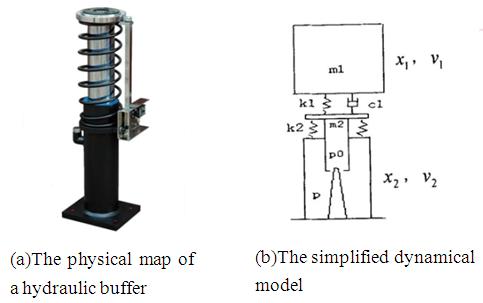 | Figure 1. A hydraulic buffer with a throttle shaft |
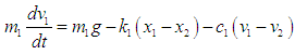 | (1) |
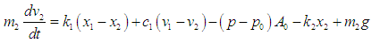 | (2) |
 | (3) |
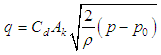
 | (4) |
 | (5) |
2.2. FE Modelling for Collision Analysis
2.2.1. The Simplified 3D FE Impact Model
- The mass of the plunger is so small compared with the elevator carriage that the plunger can be replaced by a circular steel plate in FE modeling. Three attachment points, which are used to simulate the fixed pedestal of the buffer, are established in appropriate positions and a connector element property is given to characteristic lines between the plunger and attachment points to represent the effect of fluid resistance of the buffer under an impact. The elevator carriage is simplified as a mass block with same quality. Then, the simplified model is established shown in Figure 2.
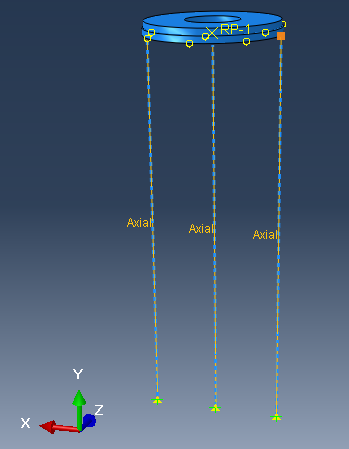 | Figure 2. Simplified FE model of the buffer |
2.2.2. Boundary Conditions and Loading
- The gravitational field is applied to the whole model. All the degrees of freedom except those represent the vertical translational motion of the plunger and the mass block, which represents the elevator carriage, and the degrees of freedom of three attachment points connected with the connector element are constrained.
2.3. The FE Modeling for the Elevator Carriage
2.3.1. The 3D Model of the Elevator Carriage
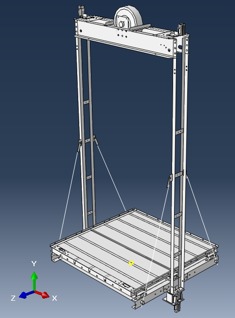 | Figure 3. FE model of the elevator carriage |
2.3.2. Boundary Conditions and Loading
- The gravitational force is applied to the whole model. All the degrees of freedom except the vertical translational motion of four contact areas between the guide roller and guide way are constrained. An acceleration is applied to the position where the elevator carriage with an initial velocity of 2 m/s impacts the buffer.
3. Results
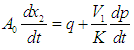
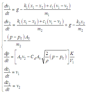
- Equation (5) was solved by MATLAB and the relationships between the pressure/velocity and time can be obtained. The pressure-velocity curve is shown in Figure 4. The velocity of the plunger reaches the maximum at the collision, and then decreases gradually during the impact process. The pressure increases rapidly when the buffer is subjected to an impact, and then decreases with the reduction of velocity of the plunger. In later stage of the buffering process, the piston nearly stops and the pressure decreases rapidly to the initial pressure value in the piston chamber.
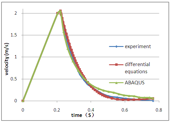 | Figure 4. Velocity-time curve of the elevator carriage |
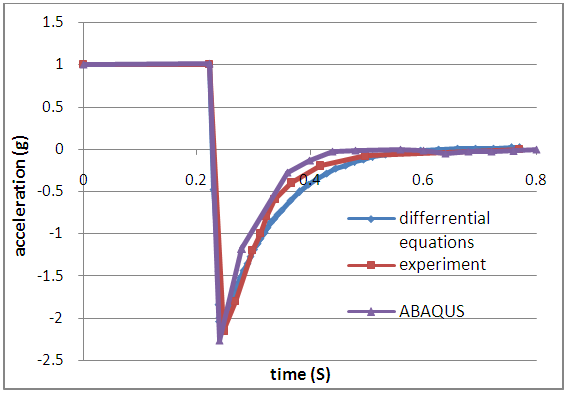 | Figure 5. Acceleration-time curve of the buffer |
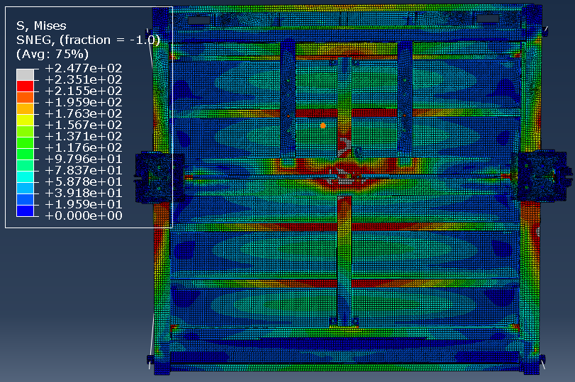 | Figure 6. Stress nephogram at the bottom of the elevator carriage |
4. Conclusions
- 1) A simplified FE model has been established to model an impact between the elevator carriage and buffer. The connector element in ABAQUS is used to simulate the hydraulic component of the buffer. The results obtained by theoretical calculations, FE modeling, and experimental tests, which matched well, illustrated the accuracy of the simplified FE model for collision analysis.2) Based on the concept of equivalent physical parameter, the model proposed in this article represents the nonlinear dynamic characteristics of the hydraulic buffer with fewer parameters. This indicates that the modeling method has a great engineering application value.3) According to the FE analysis results, the stress of the contact area of bottom beam is so high that it deforms plastically and absorbs energy to protect the elevator carriage and its passengers from injury in the case of elevator falling to the pit bottom.4) In this article, buffer with throttle shaft were investigated. The method developed in this paper could be further applied to study buffers with different throttling types and different elevator carriages.