A. K. H. Kwan, Y. Ouyang
Department of Civil Engineering, The University of Hong Kong, Hong Kong, China
Correspondence to: A. K. H. Kwan, Department of Civil Engineering, The University of Hong Kong, Hong Kong, China.
| Email: |  |
Copyright © 2017 Scientific & Academic Publishing. All Rights Reserved.
This work is licensed under the Creative Commons Attribution International License (CC BY).
http://creativecommons.org/licenses/by/4.0/

Abstract
Most theoretical models of non-uniform concrete confinement use empirical equations and thus are applicable only to limited ranges of geometric and material parameters. In light of such shortcomings, a novel finite element (FE) method is proposed to explicitly compute the non-uniform lateral confining stresses in the concrete section. To determine the lateral stresses, the lateral strains are divided into two components: an elastic component and an inelastic component, and a 2-dimensional FE analysis of the concrete section with the inelastic laterals strains taken as initial strains is carried out. Since the lateral stresses and inelastic lateral strains are inter-related, an iterative process of evaluating the lateral stresses from the inelastic lateral strains by FE analysis and then evaluating the inelastic lateral strains from the lateral stresses by a lateral strain model is employed until convergent results are obtained. This FE method is herein applied to square concrete-filled steel tube columns.
Keywords:
Concrete-filled steel tube (CFST), Confinement effect, Finite element analysis
Cite this paper: A. K. H. Kwan, Y. Ouyang, A Novel Finite Element Method for Analysing the Confinement Effect in Concrete-Filled Steel Tubes, Journal of Civil Engineering Research, Vol. 7 No. 2, 2017, pp. 57-62. doi: 10.5923/j.jce.20170702.04.
1. Introduction
A concrete-filled steel tube (CFST) has higher strength and ductility than traditional reinforced concrete, owing to the confinement effect therein. It has become widely adopted in bridges, e.g. Hejiang Bosiden Bridge and Guangzhou Yajisha Bridge, and tall buildings, e.g. Shenzhen KK100. However, the effectiveness of confinement in CFST is dependent on the section shape and loading type. In theory, a circular CFST column under axial loading has uniform confinement over the entire concrete section before any local buckling occurs, whereas a non-circular (rectangular, elliptical or polygonal) CFST column under any loading or a circular CFST under eccentric loading has non-uniform and generally less effective confinement.Many empirical axial strength and stress-strain models of confined concrete have been developed by incorporating the effects of confinement, whether uniform or non-uniform, in terms of empirical factors dependent on the geometric and material parameters without explicit consideration of the actual distribution of confining stresses [1-7]. In a recent study by Yu et al. [8, 9] on concrete confined by fibre-reinforced polymer (FRP), the finite element (FE) method was employed to analyse the confining stresses. A pivotal step was taken to simulate the interaction between the laterally expanding concrete and the confining FRP by making solution-dependent adjustments to the dilation angle of the plastic flow potential of the concrete.To avoid such complicated adjustments, the authors have developed a novel FE model, which allows directly computation of the inelastic components of the lateral strains, from which the confining stresses can be evaluated [10, 11]. This paper presents the key features of the FE model and some numerical results obtained for square CFST.
2. Concrete Modelling
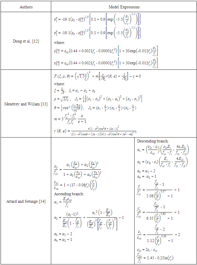
This model simulates the constitutive behaviour of concrete under confinement using the lateral stain-axial strain relation developed by Dong et al. [12], the triaxial failure surface developed by Menétrey and Willam [13] and the axial stress-strain relation of confined concrete developed by Attard and Setunge [14]. Detailed mathematical formulations of the three models are presented in Table 1 for reference.According to Dong et al. [12], the lateral strains of concrete in the two in-plane directions each comprises of two components, an elastic component and an inelastic component. Based on this postulation, the in-plane principal lateral strains ε1 and ε2 in each concrete element can be expressed as  and
and  in which
  and
and  are the elastic components, and
  and
and  are the inelastic components. With the inelastic components taken as initial strains, the constitutive equation of concrete at element level may be expressed as:
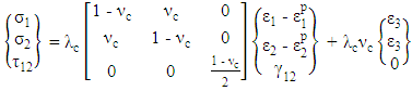 | (1a) |
 | (1b) |
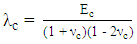
where Ec and νc are the Young’s modulus and Poisson’s ratio of the concrete. The inelastic components in Eq. (1a) are dependent on the axial strain in the longitudinal direction ε3, the lateral confining stresses σ1 and σ2, and the concrete cylinder strength fc, as given by: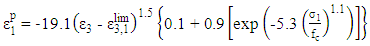 | (2a) |
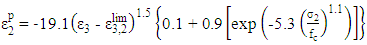 | (2b) |
The expressions of  and
and  can be found in Table 1.
Table 1. Adopted concrete models
 |
| |
|
Triangular three-noded (T3) elements are used. Hence, the axial strain ε3 at the centroid of the T3 element is used in Eqs. 1 and 2. The stiffness matrix equation of the concrete elements in the global coordinate system is derived as: | (3) |
in which ∆ is the area of the T3 element; B is the strain-displacement matrix of the T3 element; A is the strain transformation matrix converting the global lateral strain vector {εx εy γxy}T to the local principal strain vector {ε1 ε2 γ12}T; u is the nodal displacement vector {u1 υ1 u2 υ2 u3 υ3}T for the T3 element;  is the local inelastic strain vector
  is the axial strain vector {ε3 ε3 0}T in both local and global coordinate systems; and C is the constitutive matrix of the concrete.The triaxial failure surface developed by Menétrey and Willam [13] is given by:
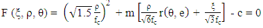 | (4) |
where ξ is the hydrostatic length; ρ is deviatoric length; θ is the Lode angle; m is the friction parameter; e is the out-of-roundness parameter; and c is the cohesion parameter. The uniaxial tensile strength ft is assumed as -0.1fc. When Eq. (4) is only describing the failure surface, c should be equal to 1. The value of e can be derived by putting σ1 = 0 and σ2 = σ2 = 1.5∙fc0.925 into Eq. (4):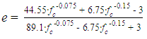 | (5) |
as per the suggestion by Papanikolaou and Kappos [15] that the biaxial-to-uniaxial compressive strength ratio of concrete should be given by 1.5∙fc-0.075. As far as the failure surface is concerned, the compressive strength of confined concrete fcc is equivalent to σ3 in Eq. (4) and can be calculated from the lateral confining stresses σ1 and σ2 at each iteration step. The relation between the axial strain ε3 and the axial stress σ3 (different from σ3 in Eq. (4)) of each concrete element may be determined by Attard and Setunge’s model [14]. The mathematical expression of this model is given by: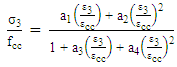 | (6) |
where εcc is axial strain at peak stress corresponding to fcc, and a1, a2, a3 and a4 are coefficients governing the shape of the stress-strain curve. It should be stressed that Attard and Setunge’s original mathematical expressions for fcc is only applicable to the cases in which the confining stresses along the two principal axes have the same magnitude, i.e. σ1 = σ2 = fr, and is replaced by Menétrey and Willam’s triaxial failure surface since the latter is more suitable for anisotropic cases. fr is also used to determine other parameters in Attard and Setunge’s model. When σ1 and σ2 are not equal to each other, fr is assumed to be the minimum of σ1 and σ2, as a compromised approach.
3. Nonlinear FE Analysis of Square CFST
The analysis procedure for axially loaded square CFST columns is illustrated in Fig. 1.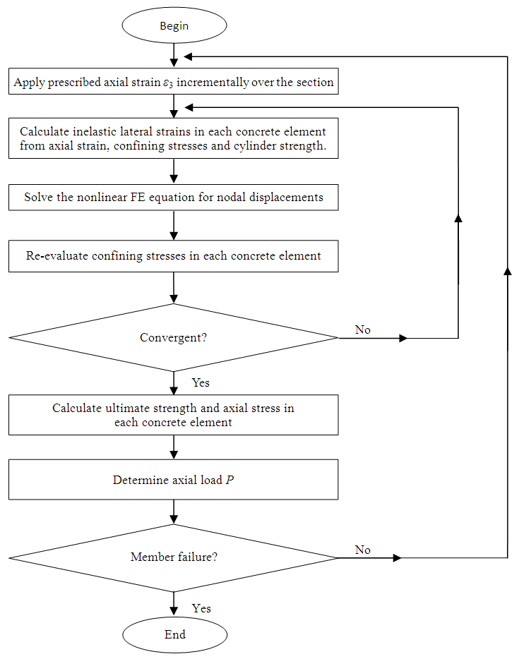 | Figure 1. Procedures for the FE analysis |
The axial strain ε3 of each concrete is the prescribed input, the inelastic lateral strain vector  of concrete in Eq. (3) can be determined by Dong et al.’s [12] lateral strain-axial strain relation. Likewise, the plastic strain vectors
  and
and  of steel can be determined by von-Mises yield criterion and the associated plastic flow. Subsequently, the global stiffness matrix equation can be assembled as:
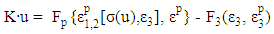 | (7) |
where Fp and F3 are load vectors related to the residual strains (inelastic lateral strains of concrete and plastic strains of steel) and axial strains in the concrete elements and steel elements. In Eq. (7), the residual strain vector on the right hand side is dependent on the nodal displacement vector on the left hand side. An iteration process is adopted to calculate the approximate solutions to Eq. (7) in each loading step. More specifically, a nodal displacement vector ui can be calculated using the current values of axial strains and confining stresses in Step i: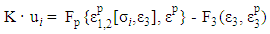 | (8) |
Then the new nodal displacement vector can be used to produce a new stress vector  which is used to compute the confining stresses for the i+1th iteration:
 | (9) |
where r is the relaxation factor. Normally the value of r is set between 0.3 and 0.7 to maintain the convergence rate during the iteration process.After the principal lateral stresses σ1 and σ2 of each concrete element are converging to steady values, i.e. their approximate solutions are found, they can be used to evaluate fcc via Menétrey and Willam’s triaxial failure surface. With the input of ε3, fcc, fr = min{σ1, σ2}, and the use of Attard and Setunge axial stress-strain relation, the axial stress σ3 of each concrete element can be evaluated. Meanwhile, the axial stress σ3 of each steel element is determined also by von-Mises yield criterion and the associated plastic flow. The force P can be calculated by integrating σ3 over the whole CFST section. If there is flexural behaviour involved other than axial compression, an extra level of iteration involving member analysis should also be added to the procedure.
4. Applications
The FE model is verified against the experimental results of 3 axially loaded square CFST columns from Sakino et al.’s publication [16]. The sectional edge length for the columns CR4-A-4-1, CR4-C-4-1 and CR4-D-4-1 are 148 mm, 215 mm and 323 mm respectively; the steel tubes for all three have yield strength of 262 MPa and thickness of 4.38 mm; the cylinder strengths of concrete are 40.5 MPa for CR4-A-4-1 and 41.1 MPa for the other two. In Fig. 2, the peak loads of CR4-A-4-1, CR4-C-4-1 and CR4-D-4-1 predicted by the FE model are 0.94, 1.02 and 0.98 times their respective experimental results; as far as the residual strength at ε3 = 4.0% is concerned, those multiples will become 0.94, 0.90 and 0.86. Overall, the predictions by the FE model agree quite well with the test results.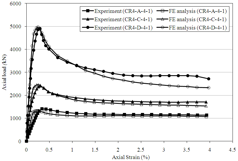 | Figure 2. Load-strain curves |
The corner effect is also studied with the help of the FE model. Fig. 3 shows the simulated distributions of axial stress for a series of axially loaded square CFST columns with edge length of 200 mm, tube thickness of 4 mm, S355 steel, Grade 80 concrete and corner radii of 10, 30 and 50 mm. It is discovered that the confinement effect is better at the corners and centre of the section. As the corner radius increases, the effectively confined concrete areas at ε3 = 4.0% will increase, hence the residual strength of the column will be maintained at a higher level.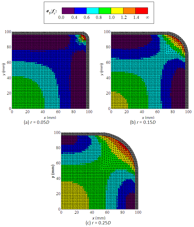 | Figure 3. Concrete axial stress contour at ε3 = 4.0% |
5. Conclusions
This paper has presented a novel FE method that utilizes Dong et al.’s lateral strain-axial strain model, Menétrey and Willam’s triaxial failure surface and Attard and Setunge’s axial stress-strain model under confined condition to analyse the passive confinement effect induced by the lateral expansion of concrete within CFST. The use of initial strains in the formulation of the global stiffness matrix equation is the key to compute passive confining stresses in the FE analysis. Owing to this new tool, the load-strain relation and the axial stress contour of CFST can be simulated, thus enabling further exploration on various phenomena in CFST, such as the corner effect.
References
| [1] | Hajjar JF, Molodan A, Schiller PH. A distributed plasticity model for cyclic analysis of concrete-filled steel tube beam–columns and composite frames. Engineering Structures 1998; 20(4-6): 398-412. |
| [2] | Susantha KAS, Ge HB, Usami T. Uniaxial stress-strain relationship of concrete confined by various shaped steel tubes. Engineering Structures 2001; 23(10): 1331-1347. |
| [3] | Fujimoto T, Mukai A, Nishiyama I, Sakino K. Behavior of eccentrically loaded concrete-filled steel tubular columns. Journal of Structural Engineering, ASCE 2004; 130(2): 203-212. |
| [4] | Cai J, He ZQ. Axial load behaviour of square CFT stub column with binding bars. Journal of Constructional Steel Research 2006; 62(5): 472-483. |
| [5] | Hatzigeorgiou GD. Numerical model for the behavior and capacity of circular CFT columns, Part I: Theory. Engineering Structures 2008; 30(6): 1573-1578. |
| [6] | Liang QQ, Fragomeni S. Nonlinear analysis of circular concrete-filled steel tubular short columns under eccentric loading. Journal of Constructional Steel Research 2010; 66(2): 159-169. |
| [7] | Zhao H, Kunnath SK, Yuan Y. Simplified nonlinear response simulation of composite steel-concrete beams and CFST columns. Engineering Structures 2010; 32(9): 2825-2831. |
| [8] | Yu T, Teng JG, Wong YL, Dong SL. Finite element modeling of confined concrete-I: Drucker-Prager type plasticity model. Engineering Structures 2010; 32(3): 665-679. |
| [9] | Yu T, Teng JG, Wong YL, Dong SL. Finite element modeling of confined concrete-II: Plastic-damage model. Engineering Structures 2010; 32(3): 680-691. |
| [10] | Lo SH, Kwan AKH, Ouyang Y, Ho JCM. Finite element analysis of axially loaded FRP-confined rectangular concrete columns. Engineering Structures 2015; 100(1): 253-263. |
| [11] | Ouyang Y, Lo SH, Kwan AKH, Ho JCM. A new analysis method for polymer-confined concrete columns. Structures and Buildings 2016; 169(12): 892-911. |
| [12] | Dong CX, Kwan AKH, Ho JCM. A constitutive model for predicting the lateral strain of confined concrete. Engineering Structures 2015; 91: 155-166. |
| [13] | Menétrey P, Willam KJ. Triaxial failure criterion for concrete and its generalization. ACI Structural Journal 1995; 92(3): 311-318. |
| [14] | Attard MM, Setunge S. Stress-strain relationship of confined and unconfined concrete. ACI Materials Journal 1996; 93(5): 432-441. |
| [15] | Papanikolaou VK, Kappos AJ. Confinement-sensitive plasticity constitutive model for concrete in triaxial compression. International Journal of Solids and Structures 2007; 44(21): 7021-7048. |
| [16] | Sakino K, Nakahara H, Morino S, Nishiyama I. Behavior of centrally loaded concrete-filled steel-tube short columns. Journal of Structural Engineering, ASCE 2004; 130(2): 180-188. |

 Abstract
 Reference
 Full-Text PDF
 Full-text HTML