-
Paper Information
- Next Paper
- Previous Paper
- Paper Submission
-
Journal Information
- About This Journal
- Editorial Board
- Current Issue
- Archive
- Author Guidelines
- Contact Us
Journal of Civil Engineering Research
p-ISSN: 2163-2316 e-ISSN: 2163-2340
2017; 7(2): 53-56
doi:10.5923/j.jce.20170702.03

A Method for Dividing the Soil Layers of a Slope in Finite Element Simulations
 Abstract
 Reference
 Full-Text PDF
 Full-text HTML
Xing Huang, Gongfa Chen, Jinyang Zhong, Yuansheng Peng, Jiqiao Zhang
School of Civil and Transportation Engineering, Guangdong University of Technology, Guangzhou, China
Correspondence to: Gongfa Chen, School of Civil and Transportation Engineering, Guangdong University of Technology, Guangzhou, China.
| Email: |  |
Copyright © 2017 Scientific & Academic Publishing. All Rights Reserved.
This work is licensed under the Creative Commons Attribution International License (CC BY).
http://creativecommons.org/licenses/by/4.0/

In the finite element simulations in geotechnical engineering, the partition and the meshing of the soil layers have been one of the most difficult tasks. This paper proposed a method, in which a prescribed field variable in ABAQUS was used to describe the soil layers of a slope and divide the soil indirectly. Instead of distinctly meshing the different soil layers, the elements in different soil layers were assigned different materials with regard to the prescribed field variable. Compared with the conventional meshing method in the partition of the soil layers, the proposed field variable method can simplify the meshing task. It makes the FE mesh more regular hence the simulations converge more easily. Therefore, the field variable method will have more advantages in assigning the soil materials to the model. The proposed method can be used in the practical engineering simulations and enhance the application of the finite element analyses.
Keywords: Slope stability, Soil layers, Finite element analysis, Meshing
Cite this paper: Xing Huang, Gongfa Chen, Jinyang Zhong, Yuansheng Peng, Jiqiao Zhang, A Method for Dividing the Soil Layers of a Slope in Finite Element Simulations, Journal of Civil Engineering Research, Vol. 7 No. 2, 2017, pp. 53-56. doi: 10.5923/j.jce.20170702.03.
Article Outline
1. Introduction
- Slope stability is one of the most intensive research topics in the geotechnical engineering. Correctly analyzing the stability of a slope has a great significance to the construction and the safety of the slope. Most of the early analyses and evaluations were based on the practical experience or using the engineering analogy to make a judgment. As in the limit equilibrium theory of geotechnical mechanics, the safety factor can be achieved by using the slice method to analyze the stability of the slope which is assumed in the ultimate balance situation. It does not consider the relation between the stress and strain, so it is not able to predict the process of losing stability of the slope. [1]In recent years, the engineering practice and computational simulations illustrate that there are connections between the instability and the failure of the slope. With the development of nonlinear elastic-plastic finite element analyses, it is capable of using the finite element method to analyze the stability of the slope. [2] If the method can guarantee the precision, it can simulate the slope with complex geographic conditions. At the same time, it can consider the influence of the deformation and the nonlinear constitutive relation of the soil. At present, the finite element method has been commonly employed to simulate the slope stability.In the creation of the finite element model, meshing the model could be the most time-consuming task if variations of the soil layers (i.e., geographic and geomorphic conditions) are complex. In the conventional meshing method, the soil will be divided into several layers according to the geological conditions and then the soil layers will be meshed separately. In a simple model, the conventional method can produce a high-quality mesh. In the case with complex soil layers, the conventional method often produces a low-quality mesh or even fails. It is also very time-consuming to refine the mesh in later period. To solve the meshing problem mentioned above, this paper proposes an assignment method of material properties of soil layers. Following Chen et al (2015) [3], the material properties in different soil layers are made dependent on the field variable. In this method, it is unnecessary to partition and mesh the different layers separately. Hence it can produce a better mesh and achieve more accurate results than the conventional meshing method.
2. Model
- The simulation was based an actual slope, the initial and the excavated configurations of the slope were shown in Figure 1. From top to bottom, the soil materials are as follow: the first layer is brown-red and yellow silty clay, the second layer is brown-yellow completely-weathered granite, the third layer is yellow-brown weathered granite. Model Change, one of the functionalities in ABAQUS, was used to simulate the excavation process of the slope. A 4-level slope was achieved in the end. The slope rate of the first and the second steps is 1:0.75, the height is up to 10 m, the width of these steps is 2 m. The slope rate of the third step is 1:1.0, the height is up to 10 m, the width of this step is 2 m. The slope rate of the fourth step is 1:1.0, the height is up to 8 m.
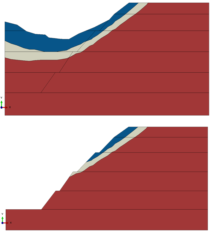 | Figure 1. The configurations before and after the excavation |
 , the cohesive force is
  , the angle of internal friction is
  ; the bulk density of the yellow-brown completely granite is
  , the cohesive force is
  , the angle of internal friction is
  ; the bulk density of the brown-red and yellow silty clay is
  , the cohesive force is
  , the angle of internal friction is
  .
. 3 Method
3.1. The Conventional Method of Dividing the Soil Layers
- (1) Based on the engineering drawings, the key points of the soil layers are determined.(2) According to the coordinates of the key points, the soil is divided into several layers, which are meshed separately.(3) The different layers are assigned the different material properties.The model created by using the conventional method is usually irregular at the layer boundaries. Because of its irregularity, it often produces a low-quality mesh. In the end it influences the simulation convergence. It is very time-consuming to refine the finite element mesh in the later period.
3.2. The Method Using the Field Variable to Divide the Soil
- (1) This method is using the temperature field in ABAQUS to assign the soil material to the model.(2) Based on the engineering drawings, the soil layers will be determined. The coordinates of the key points of the soil layers will be read into an in-house FORTRAN program.(3) In the property module, the soil material will be set dependent on the temperature field. In addition, the temperature field is added to describe the soil layers.Figure 2 shows the soil layers created by the conventional method and the field variable method. The method using the field variable is different from the conventional method. Firstly, according to the coordinates of those points, the model will be divided into several layers in conventional method. In the field variable method, the coordinates will be read into the FORTRAN program.
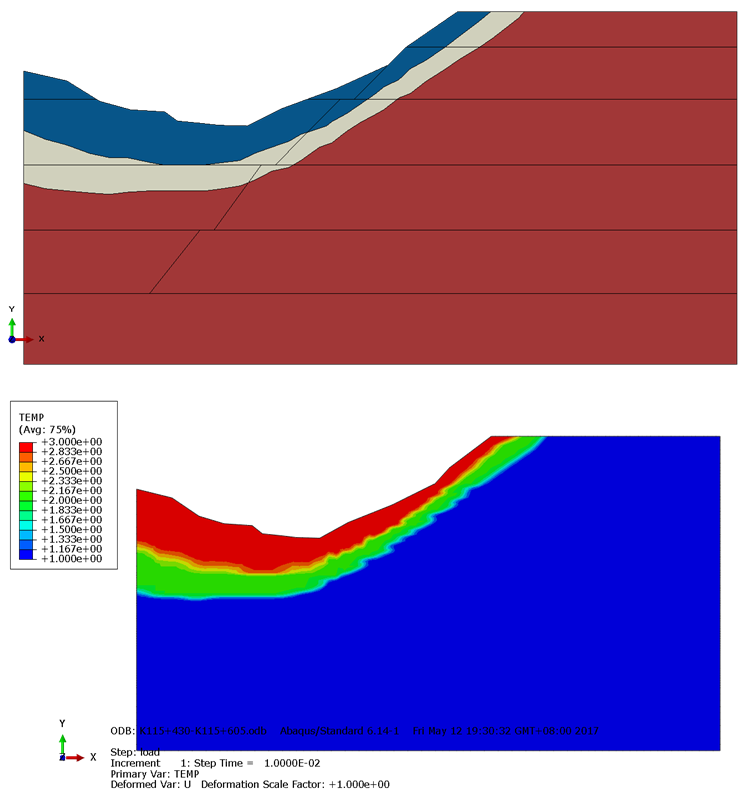 | Figure 2. The comparison of soil layers between the conventional method and the method of field variable |
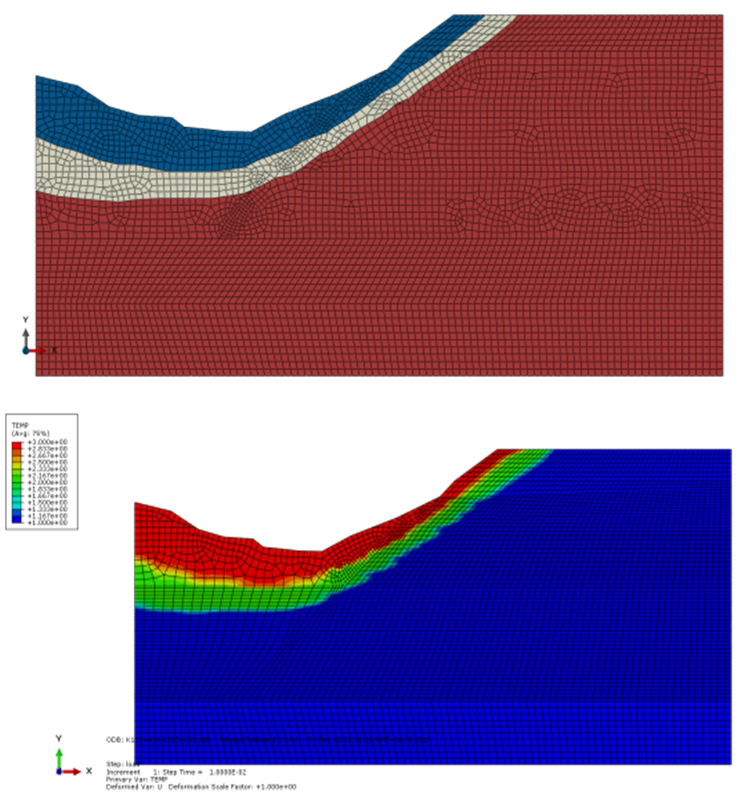 | Figure 3. The comparison of mesh between the conventional method and the method of field variable |
4. Analysis
- Figure 4 is the comparison of the plastic strain between the conventional method and the field variable method. Figure 5 is the comparison of the displacement between the conventional method and the field variable method. The Figures show that the equivalent plastic strain near the toe of the slope of these two methods is increasing rapidly with the iteration step. The strain area of the field variable method goes through the top of the slope and also the strain area of the conventional method almost goes though the top of the slope. Furthermore, the strain area and the displacement all have the rising tendency. They not only have the similar tendency, but also the similar numerical values.
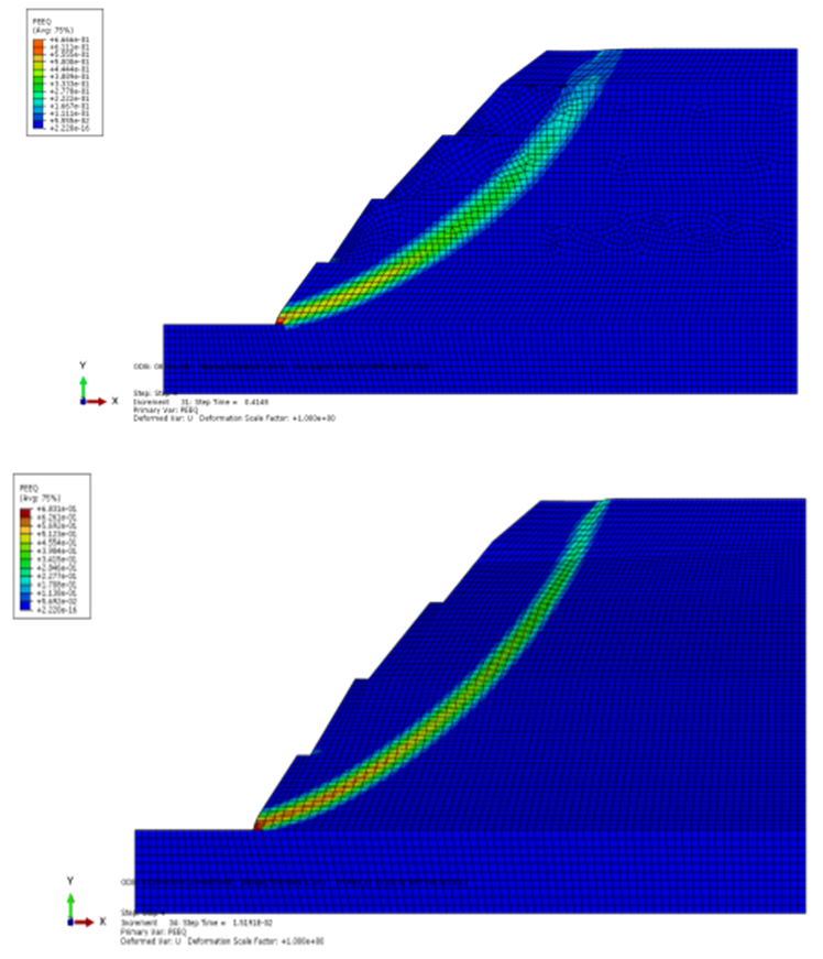 | Figure 4. The comparison of the plastic strain between the conventional method and the field variable method |
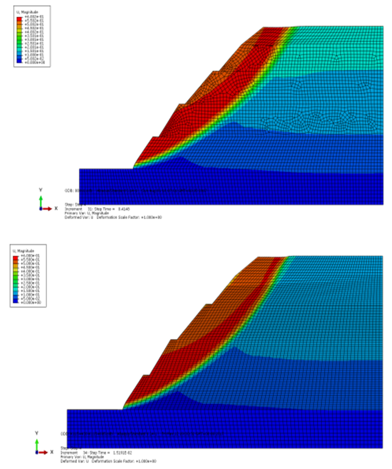 | Figure 5. The comparison of the displacement between the conventional method and the field variable method |
5. Conclusions
- This paper has proposed a new method to assign material properties to soil layers in the finite element model of a slope. Through using the in-house FORTRAN subroutine, the field variable in ABAQUS can be used to assign the soil material to the model and divide the soil indirectly. This paper has compared the differences between the proposed field variable method and the conventional meshing method. It has also compared the disadvantages of the conventional meshing method and the advantages of the proposed field variable method. An actual slope has been used as an example in this article and the results have been respectively achieved from these two methods. With the comparisons between the results of these two methods, the tendency and the numerical values of the displacement and the plastic strain obtained from two methods are really similar. To some extent, the results of the field variable method are better than those of the conventional meshing method. Therefore, the effectiveness and the feasibility of the field variable method were verified in this article. It is concluded that the proposed field variable method will have a wide application prospect in geotechnical simulations.