-
Paper Information
- Next Paper
- Paper Submission
-
Journal Information
- About This Journal
- Editorial Board
- Current Issue
- Archive
- Author Guidelines
- Contact Us
Journal of Civil Engineering Research
p-ISSN: 2163-2316 e-ISSN: 2163-2340
2017; 7(2): 35-45
doi:10.5923/j.jce.20170702.01

Full-range and Long-term Behaviour of Prestressed Concrete Bridges with Corrugated Steel Webs
 Abstract
 Reference
 Full-Text PDF
 Full-text HTML
Francis T. K. Au1, X. C. Chen1, 2, R. J. Jiang3, T. Huang1
1Department of Civil Engineering, The University of Hong Kong, Hong Kong, China
2Research and Technology Center, WISE-TECH Engineering Consulting Co. Ltd, Shenzhen, China
3Research Center, Shenzhen Municipal Engineering Design and Research Institute, Shenzhen, China
Correspondence to: Francis T. K. Au, Department of Civil Engineering, The University of Hong Kong, Hong Kong, China.
| Email: |  |
Copyright © 2017 Scientific & Academic Publishing. All Rights Reserved.
This work is licensed under the Creative Commons Attribution International License (CC BY).
http://creativecommons.org/licenses/by/4.0/

Prestressed concrete bridges with corrugated steel webs have emerged as a promising bridge form due to their remarkable advantages such as efficient prestressing of concrete, high buckling strength of steel webs and lightness. The full-range and long-term behaviour of these bridges was studied both numerically and experimentally. A sandwich beam theory was developed to investigate both the static and dynamic behaviour numerically. In the development of numerical models, special emphasis was placed on the modelling of corrugated steel webs, external prestressing tendons, diaphragms, and the interaction between web shear deformation and local flange bending. The numerical models were verified by tests. By using the numerical models proposed, the static service behaviour, dynamic properties and long-term behaviour were studied. The sectional ductility, deformability and strength were evaluated by nonlinear analysis taking into account the actual stress-strain curves and path-dependence of materials. The failure mechanisms were studied experimentally and numerically for more accurate evaluation of safety-related attributes such as ultimate load, ductility and deformability. The formation of plastic hinge and its size were also studied thoroughly in view of their importance in the prediction of full-range behaviour. The long-term behaviour was also studied numerically and experimentally. Some design recommendations are provided here.
Keywords: Corrugated steel webs, Full-range behaviour, Long-term behaviour, Prestressed concrete
Cite this paper: Francis T. K. Au, X. C. Chen, R. J. Jiang, T. Huang, Full-range and Long-term Behaviour of Prestressed Concrete Bridges with Corrugated Steel Webs, Journal of Civil Engineering Research, Vol. 7 No. 2, 2017, pp. 35-45. doi: 10.5923/j.jce.20170702.01.
Article Outline
1. Introduction
- In the search for efficient structural forms for bridges, prestressed concrete bridges with corrugated steel webs as shown in Figure 1 have emerged as a promising solution. This form of bridge has some remarkable advantages such as lightness, high buckling strength of steel webs, efficient prestressing of concrete, and easy maintenance. In 1986, the first bridge of this type, Cognac Bridge, was built in France [1]. Its successful application and various advantages over the conventional prestressed concrete bridges have prompted researchers and construction companies in various countries, including Japan, USA, China, Germany, etc. to continue with the relevant work in research and development. Over 200 concrete bridges with corrugated steel webs have been built. Hereafter in this paper, this form of bridge is assumed unless otherwise stated.
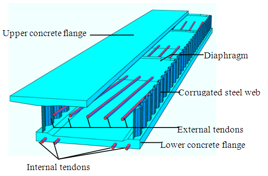 | Figure 1. A prestressed concrete bridge with corrugated steel webs (some parts of the bridge are omitted for clarity) |
2. Experimental Programme
- This section illustrates the experimental programme, while the verification and calibration of the proposed numerical models using the experimental results are described in the subsequent sections.
2.1. Experimental Programme for Static and Dynamic Behaviour
- Some prestressed concrete beam specimens with corrugated steel web were fabricated for testing. One sample is shown in Figure 2. The flanges of these specimens were cast of high-strength concrete. The thickness of corrugated steel webs was 5 mm. Embedment connections were provided between the concrete flanges and corrugated steel web.
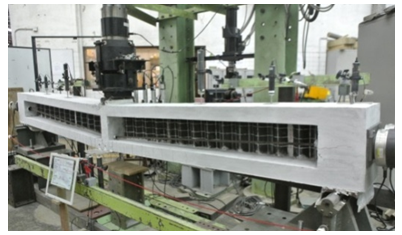 | Figure 2. One of the tested beams |
|
2.2. Experimental Programme for Long-term Time-dependent Behaviour
- A prestressed concrete beam with a single corrugated steel web, namely Specimen L-1 as shown in Table 1, was fabricated for long-term monitoring. The specimen, cast of grade C60 concrete, was simply supported and post-tensioned by an initial effective prestressing force of 200.95 kN. Three dial gauges were used to measure the variations of deflection with time, while the variations of prestress were measured by load cells under the anchorages.
3. An Extended Sandwich Beam Model
3.1. Beam Model
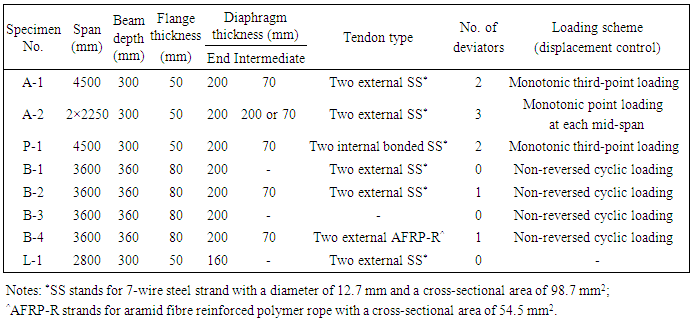
- Corrugated steel sheets can be analysed by the theory of orthotropic plates [4]. Elgaaly et al. [5], Combault [6], and Johnson and Cafolla [7] found the axial stiffness of corrugated steel web negligible.The sandwich beam model proposed by Chen et al. [8] and Chen et al. [9] for this type of bridges is adopted. Figure 3(a) shows the simplified typical cross section characterised by the height hw of web and the distance h between centroidal axes of flanges, and Figure 3(b) shows the typical corrugations. The corrugated steel sheet is modelled as an orthotropic plate.
 | Figure 3. Configuration of bridge: (a) A simplified cross section; and (b) One full corrugation of steel web |
 | (1) |
 and B = Bg+Bf with Bf being the sum of local flexural rigidities of flanges about their respective centroidal axes and Bg being the global flexural rigidity of flanges about the centroidal axis of the entire beam section assuming uniform stress in each flange;
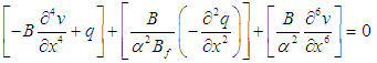
 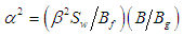 with Sw being the shear rigidity of corrugated webs; β = h/hw; and q is the distributed load.The terms within the first set of square brackets represent the basic case without shear deformation, i.e. the case of Euler-Bernoulli beam. The term in the second set of square brackets arises from web shear deformation. The term in the third set of square brackets results from the interaction between web shear deformation and local bending of flanges.A C1 three-node beam finite element is formulated with its displacement vector comprising the longitudinal displacement u of the beam axis, deflection v and normal rotation φ, which are interpolated by linear, Hermite cubic and quadratic polynomials respectively. With the nodes labelled locally as a, b and c from the left end of element, the element displacement vector is
 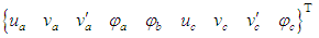 . As the constraint index count of the shear stiffness matrix is above zero, there is low risk of shear locking.
3.2. Diaphragms
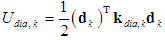
- These bridges are often provided with end and intermediate diaphragms. The diaphragm resists the adjacent web shear deformation and prevents the relative longitudinal movement of the flanges. The action of the k-th diaphragm located at an edge node of element can be modelled by an internal couple, which needs to satisfy the condition of compatibility and equilibrium at the web-flange junction at the diaphragm [8], resulting in the strain energy Udia,k as
 | (2) |
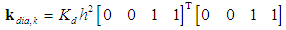 | (3) |
3.3. External Tendons
- The external tendons interact with the beam through anchorages and deviators. The elongation of external tendons depends on the global bridge deformation. The model of Dall’Asta et al. [10] for externally prestressed Euler-Bernoulli beams has been extended by Chen et al. [9] for this type of bridges.In brief, the profile of the external tendon is defined by the positions of end anchorages or intermediate deviators, and the additional elongation and strain of the tendon are calculated from the initial and deformed total lengths accordingly. The mesh is so chosen that the (n+1) deviators or anchorages coincide with some of the k end nodes of elements. The strain of external tendon is then obtained from the beam displacements as
 | (4) |
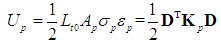 | (5) |
 | (6) |
4. Flexural Ductility of Reinforced and Prestressed Concrete Sections
- In the design of concrete bridges with corrugated steel webs, especially those with flanges made of high-strength concrete and/or those with the requirement of seismic resistance, the flexural ductility and deformability as well as strength need to be carefully examined. Evaluation of these safety-related attributes requires the reliable estimation of full-range behaviour that encompasses the service and failure behaviour.
4.1. Method of Analysis
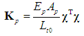
- In this study, the moment-curvature relation of reinforced concrete and partially prestressed concrete sections with corrugated steel webs is evaluated by means of a nonlinear numerical method which uses the actual stress-strain curves of the materials and considers their stress-path dependence [11, 12]. The properties of ordinary non-prestressed reinforcement and prestressing steel are also incorporated in the method so that both reinforced concrete and partially prestressed concrete sections can be studied. The material laws considering strain reversal are adopted. Figure 4(a) shows the model for both unconfined and confined concrete comprising the stress-strain curve in compression developed by Attard and Setunge [13] and that in tension proposed by Carreira and Chu [14], and Guo and Zhang [15]. The stress-strain curve recommended by Mander et al. [16] is used for non-prestressed steel as shown in Figure 4(b). The stress-strain formula for prestressing steel proposed by Menegotto and Pinto [17] is adopted here as shown in Figure 4(c). The AFRP rope is linearly elastic up to failure and has no significant yielding.
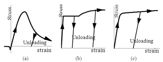 | Figure 4. Stress-strain curves of materials: (a) concrete; (b) non-prestressed steel; and (c) prestressing steel |
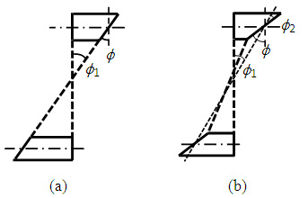 | Figure 5. Strain distribution over section depth: (a) Without interaction effects (ϕ2= 0); and (b) With interaction effects (ϕ2≠ 0) |
4.2. Effects of Interaction between Web Shear Deformation and Local Bending of Flanges
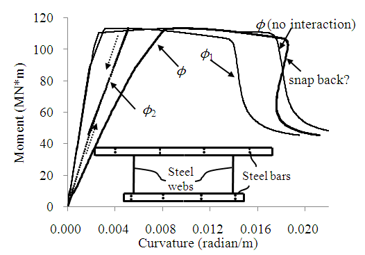
- To consider the interaction effects in the section analysis, the secondary curvature ϕ2 associated with additional local bending induced in the concrete flanges is determined upon application of the primary curvature ϕ1 to the entire section. The values of α and Bf are updated accordingly to account for material nonlinearity as necessary.The complete moment-curvature curve of the mid-span section of a simply-supported beam with corrugated webs considering interaction effects are obtained and compared with that ignoring interaction effects as shown in Figure 6. It shows that interaction has little effect on the ultimate curvature and deformability, but significantly increases the yield curvature and reduces the ductility. The total curvature ϕ considering interaction effects is found to reverse when the resisting moment M drops significantly, giving rise to a “snap back” phenomenon. It is because the secondary curvature ϕ2 decreases with the drop of resisting shear force V and bending moment M. This should be treated with caution, as the upper concrete flange may be crushed, thereby creating a kink and violating the assumptions made in the numerical model. Nevertheless, the effects of the curvature reversal on the sectional strength, ductility and deformability are insignificant.
 | Figure 6. Complete moment-curvature curves considering interaction effects |
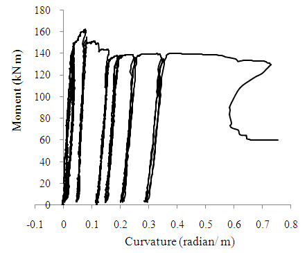 | Figure 7. Moment-curvature curve for mid-span section of Specimen B-4 |
5. Formation of Plastic Hinges
- It is inspiring to study the formation of plastic hinges in these bridges and their effect on the full-range behaviour that covers both the pre-peak-strength and post-peak- strength structural responses. The presence of shear-deformable corrugated steel webs with negligible axial stiffness and prestressing tendons certainly complicates the formation of plastic hinges. Hence in this study, the critical region length, performance of the plastic hinge and full-range behaviour of the bridges are studied.
5.1. Flexural Failure Mode
- It is observed in the tests that tensile cracks appeared first in the lower flange in the potential plastic zone around the mid-span. With the increase in loading, the tensile steel yielded and the neutral axis shifted towards the upper flange, placing the bottom of the upper flange in tensile zone. The secondary moment caused further tension and led to cracking at the bottom of the upper flange. As the displacement further increased, tensile cracks in the upper flange gradually extended upwards, followed by the crushing of top concrete. Shear crack also occurred in the upper flange later. To illustrate, the plastic hinges formed in Specimens B-1 and B-4 are shown in Figures 8(a) and 8(b) respectively.
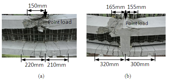 | Figure 8. Plastic hinge zones and critical region lengths: (a) Specimen B-1; and (b) Specimen B-4 |
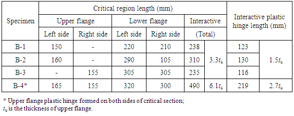
5.2. Critical Region Lengths and Plastic Hinge Lengths
- As the critical region length in the upper flange is closely related to the formation of flange plastic hinge, which is similar to a column plastic hinge, the critical region length in the upper flange is taken to include regions having [19]: (a) spalling of concrete cover; (b) penetration of spalling into concrete core region; (c) local buckling of longitudinal steel; and (d) tensile cracks at flange bottom by visual inspection. On the other hand, the critical region length in the lower flange is closely related to the full-depth plastic hinge and hence includes the region which suffers from significant tensile cracking [19]. After finishing the tests, all the loose concrete pieces were removed to expose the degree of damage before taking photographs. The observed critical regions of specimens are illustrated in Figure 8, together with the estimated critical region lengths. The plastic hinge in the upper flange is relatively small as compared to the full-depth plastic hinge length.The interaction between the critical region lengths in the upper and lower flanges results in an “interactive critical region length” lc. It is approximated as the length of the region between the sections that has sustained a rotation equal to the yield slope θy. This is illustrated in Figure 9. Transverse reinforcement should be provided within the critical region for effective confinement and strengthening of concrete.
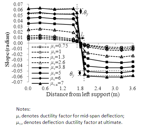 | Figure 9. Specimen B-1: Measured slope |
 | (7) |
|
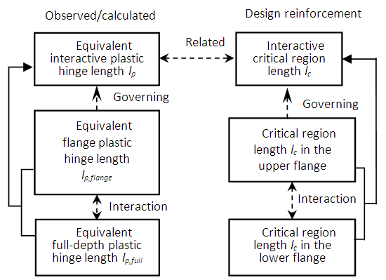 | Figure 10. Relation between various plastic hinge lengths and critical region lengths |
5.3. Interaction between Flange Plastic Hinges and Full-depth Plastic Hinge
- As elaborated in Section 5.2, the flange plastic hinge governs the full-range structural behaviour of the bridge, indicating that the equivalent interactive plastic hinge length lp is close to the equivalent flange plastic hinge length, while the effects of full-depth plastic hinge should also be taken into account. A simple formula for prediction of the equivalent interactive plastic hinge length lp was proposed as [20]
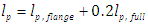 | (8) |
5.4. Simplified Method for Prediction of Full-Range Structural Behaviour
- When the plastic hinge length and sectional moment-curvature curves of a bridge are known, the deflection and slope can be obtained by integration of curvature along the span. Here, the full-range structural behaviour of this type of bridge is predicted based on the concept of the equivalent plastic hinge length. The second-order effects associated with the external tendons are also considered. For rigorous procedure, one may refer to Chen et al. [25]. In the proposed simplified method, the load-displacement and load-tendon-stress curves are approximated by tri-linear relationship as shown in Figure 11, where Pyield and Ppeak are the yielding and ultimate load respectively. It then reduces to analyse the structural states with the critical section having the yield, peak and ultimate curvature in turn, which are determined from the moment-curvature analysis first.
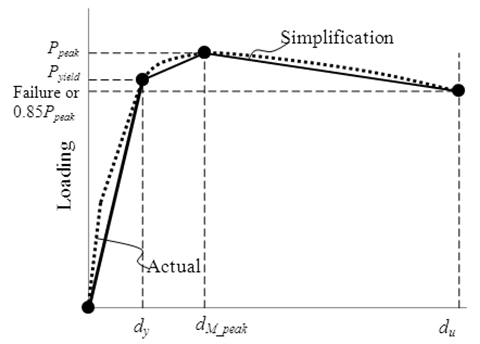 | Figure 11. Actual and simplified load-displacement curves |
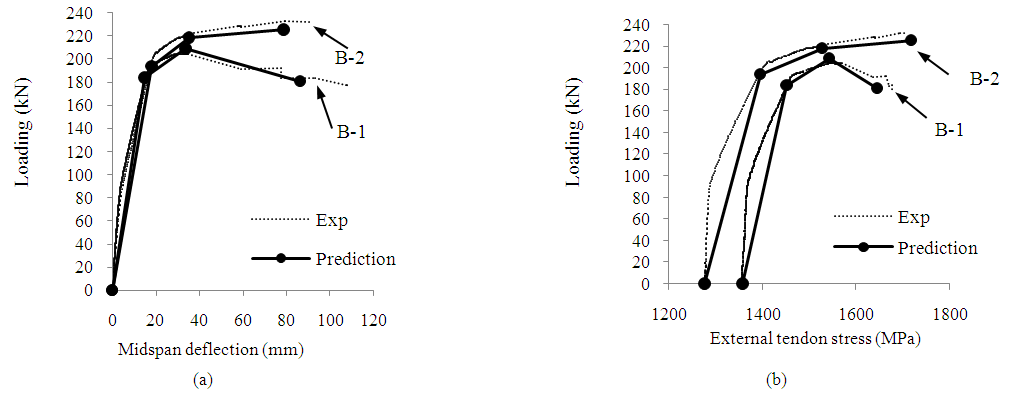 | Figure 12. Full range structural behaviour of Specimens B-1 and B-2: (a) load vs. mid-span deflection; (b) load vs. tendon stress |
6. Dynamic Properties
- Prestressed concrete bridges with corrugated steel webs are especially popular in regions of strong seismicity since they are lighter than conventional prestressed concrete bridges. However, the reduction in self-weight is also accompanied by reduction in stiffness [26]. Moreover, external prestressing tendons are usually adopted along with internal tendons, and diaphragms are always provided not only to act as deviators but also to improve the torsional resistance. All these may affect the dynamic properties.The sandwich beam model described in Section 3, which takes into account the presence of the diaphragms, the external prestressing tendons and the interaction between the web shear deformation and the flange local bending, was employed to predict the vibration characteristics of this type of bridges. The governing equation of free vibration can be obtained as
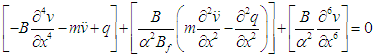 | (9) |
|
7. Long-term Time-dependent Behaviour
- Although many researchers have studied their structural behaviour, relatively little effort has been devoted to their long-term behaviour [25]. The long-term effects may result in additional deflections, loss of prestress, force redistribution and possibly additional cracking.The long-term structural behaviour is analysed using the nonlinear numerical method developed in conjunction with time-dependent material properties. Specifically, the Eurocode models for concrete creep and tendon relaxation were adopted. As the granitic aggregate available around Hong Kong has relatively low elastic modulus and high water absorption, the shrinkage is quite high. The modified Eurocode shrinkage model, which had been calibrated by Kwan et al. [27] to account for the local conditions, was used. The variation of the concrete strength and secant modulus of elasticity with time were taken from the Structures Design Manual for Highways and Railways [28] of Hong Kong. Factors including the relative humidity and air temperature were based on the laboratory monitoring as well as those recorded by the Hong Kong Observatory.Time-dependent analysis was carried out by either the time integration method (TIM) [29] or single-step method [30] adopting the age-adjusted elasticity modulus (AAEM) of concrete.A prestressed concrete beam with a single corrugated steel web was fabricated for long-term monitoring as described in Section 2. The tendon force decreased with time as shown in Figure 12(a). The measured long-term loss of prestress was 10.4%. On the other hand, the upward long-term deflection at quarter points of span and middle span both increased as much as around 80%, as shown in Figures 12(b) and 12(c) respectively. The numerical results show reasonably good agreement with the experimental results.
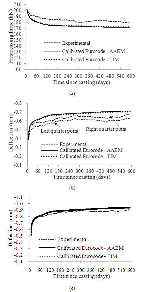 | Figure 12. Long-term behaviour (a) Total prestressing force; (b) Quarter-point defection; and (c) Mid-span deflection |
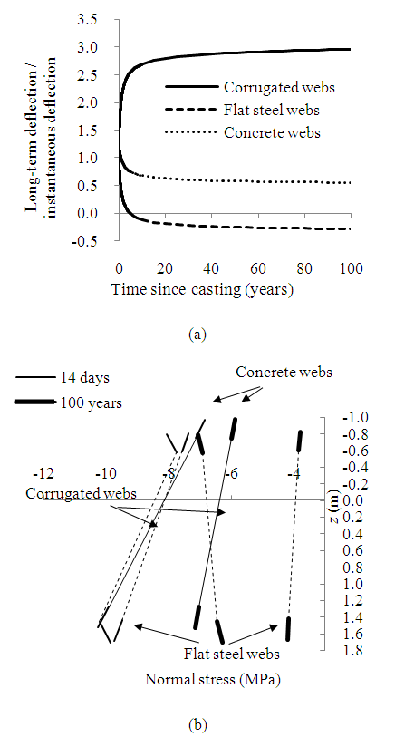 | Figure 13. Numerical example: (a) Mid-span deflection with time; (b) Normal concrete stress distribution at middle span |
8. Conclusions
- In this study, the full-range and long-term structural behaviour of prestressed concrete bridges with corrugated steel webs has been investigated both numerically and experimentally. Based on the studies, the following conclusions can be drawn:(a) Owing to the interaction between shear deformation of corrugated steel webs and local bending of concrete flanges, secondary bending moments and shear forces occur in the concrete flanges, which may violate of the common assumption of linear normal strain distribution over the entire section depth.(b) The diaphragms of this type of bridges have minor effects on the deflections, but significant effects on stress distributions and stress resultants by constraining the web shear deformation in the vicinity and relative longitudinal movement of concrete flanges.(c) For serviceability design, the shear and normal stress concentration in flanges due to the effects of diaphragm and interaction between web shear deformation and local bending of flanges should be examined carefully, especially in the vicinity of point loads and diaphragms. To relieve the stress concentration, diaphragms may be provided with haunches. At the ultimate limit state, there may be local failure of concrete flanges due to the stress concentration, especially in short bridges.(d) With α as the square root of the ratio of equivalent shear rigidity of the beam section to the flange local flexural rigidity and L as the span length, the combined parameter αL is an indication of the effects of diaphragm and interaction between web shear deformation and flange local bending. The smaller the combined parameter αL is, the more significant these effects are.(e) The diaphragms have significant effects on the natural frequencies and mode shapes only for bridges with short spans and/or lower ratios of the equivalent shear rigidity of beam section to flange local bending rigidity, namely for bridges with αL values below a certain limit.(f) The effects of diaphragm and interaction between web shear deformation and local bending of flanges reduce gradually with time. The instantaneous deflections and long-term increment of this type of bridges are larger than those of their counterparts with concrete or flat steel webs, and therefore the deflections should be examined carefully. The long-term compressive normal stresses in the concrete flanges of this type of bridges are close to those of conventional bridges with concrete webs, but obviously larger than those of conventional bridges with flat steel webs.(g) Concrete bridges with corrugated steel webs perform reasonably well in respect of sectional flexural ductility and deformability. In comparison with concrete box girder sections and solid concrete sections with comparable dimensions, concrete bridges with corrugated steel webs still perform well in respect of flexural ductility and deformability, provided that those with the same concrete sectional areas are compared. The effects of interaction between web shear deformation and local bending of concrete flanges on the sectional flexural ductility are sensitive to the arrangement of spans and loading, as well as sectional properties. The interaction effects decrease with increase of curvature. The interaction has little effect on the ultimate curvature and therefore deformability, but the interaction significantly increases the yield curvature and reduces the ductility.(h) Owing to the presence of prestressing tendons and shear-deformable corrugated steel webs with negligible axial stiffness in this type of bridges, flange plastic hinge and full-depth plastic hinge may form and interact with each other. Experimental results show that the equivalent interactive plastic hinge length, critical region length and plastic behaviour are governed by the formation of flange plastic hinge. Based on the equivalent interactive plastic hinge length estimated by an empirical formula, a simplified method is proposed to predict the full-range structural behaviour of the bridge.
9. Design Recommendations
- Some design recommendations for prestressed concrete bridges with corrugated steel webs are given below:(a) To estimate the ultimate displacement and load, it is conservative to assume the plastic hinge to form only on one side of the critical section; otherwise the strength and ultimate displacement will be over-estimated. The arrangement of external tendons also affects the ductility, deformability and ultimate load of the bridge. Providing more intermediate deviators normally reduces the secondary effects and improves the ductility and deformability.(b) The stress concentration due to effects of interaction between web shear deformation and local flange bending should be examined carefully, especially at the early stage.(c) The use of a simple factor to predict the long-term deflection based on the instantaneous deflection could be misleading. A practical way is to use the effective modulus of elasticity of concrete with creep and the shrinkage curvature.