Mekkiyah H. M., Al-Saadi S. Z.
Department of Civil Engineering, University of Baghdad, Baghdad, Iraq
Correspondence to: Al-Saadi S. Z., Department of Civil Engineering, University of Baghdad, Baghdad, Iraq.
| Email: |  |
Copyright © 2016 Scientific & Academic Publishing. All Rights Reserved.
This work is licensed under the Creative Commons Attribution International License (CC BY).
http://creativecommons.org/licenses/by/4.0/

Abstract
Stone/granular column have been used as an effective technique to improve the mechanical properties of soft clay. The study represents a new development to enhance the performance of stone/ granular column when mixed with plastic fiber (i.e. reinforced Fiber Granular Column FGC) in improving the behaviour of stone column within the soft clay when compared with Ordinary Granular Column (OGC). In this paper, consolidated undrained triaxial tests are conducted on (21) specimens with area replacement ratio of (13%) to investigate the effect of plastic fiber percentage in improving the mechanical properties for floating and end bearing granular column. The study also includes the critical state parameters assessment for (OGC) and (FGC). The results show that the increase in deviator stress for (FGC) when compared with (OGC); along with pore water pressure, critical friction angle, slope of the critical state line (M). The good evidence in this study, is the clear behaviour of state parameter (ξ), which gave a good indication to reduce the length of the column in case of (FGC) (i.e. floating column) when compared with (OGC) (i.e. end bearing column).
Keywords:
Critical State Line, Area Replacement Ratio, State Parameter
Cite this paper: Mekkiyah H. M., Al-Saadi S. Z., Experimental Study for Granular Column and Fiber Granular Column, Journal of Civil Engineering Research, Vol. 6 No. 5, 2016, pp. 119-127. doi: 10.5923/j.jce.20160605.02.
1. Introduction
In general, the soft ground contains large fractions of fine particles such as silts, and /or clay soils. Soft clay has weak strength, stiffness, drainage characteristics, high compressibility and water content. The demand for construction structures on soft soils; is forcing the geotechnical engineers to improve the soft soil. Amongst various methods of soft soil improvement, reinforcing the ground by installation of granular column/ stone column is one of the well-established and effective techniques followed worldwide [1].In the middle and southern parts of Iraq, soft soils are encountered. In recent years this technique is also proposed to be used in Iraq. The main aim of stone column reinforcement is to increase the carrying capacity and decrease the excessive and differential settlement and accelerate the consolidation rate of the soft clay.The stone column derives load carrying capacity from the lateral confining pressure from the surrounding soils [2]. The passive resistance of the native soil dictates the column performance under load. As the overburden pressure is lowest close to the surface therefore the column bulging will be greatest close to the top of the column.The stone column in nature is triaxial behavior and gains its strength from lateral support provided by the surrounding soil. Hence, the load deformation behavior can be modeled in laboratory by using triaxial tests, although that the confining pressure on the stone column in nature increase with increase its depth but actual behavior approximately with constant confining pressure is applied in chamber of triaxial cell. The triaxial tests permits the control on confining pressure, stress state, the drainage condition and the rate of loading [3, 4].Many researchers have carried out experimental, as well as, analytical studies to understand the behavior of soil reinforced with granular column.In order to enhance the performance of granular columns when improve soft clay it is imperative that the tendency of stone column to bulge should be restricted effectively. So, granular column are reinforced internally by the various options of reinforcing; using concrete plugs, chemical grouting or by adding internal inclusion (geogrids, plastic fibers etc.) will stiffen the column and increase the lateral stresses in the surrounding soil, and accordingly its bearing capacity.[5] investigated analytically and experimentally the response of granular columns reinforced with horizontally laminated geotextile sheets in the top layers. The proposed analytical method is verified through laboratory triaxial tests carried out on sand columns reinforced with four layers of horizontal geotextile sheets. Analytical results show that the reinforced granular column embedded in clay exhibits a significant increase in axial resistance over columns loaded under constant chamber pressure.[6] performed experimental analysis on behavior of random fiber mixing in granular pile, with parametric studies to observe the effect of fiber content, fiber length and fiber depth on load carrying capacity of granular pile. [7] performed experimental tests on expansive clays with stone column reinforced by fiber material in good agreement with [6]. Based on their experimentation, [7] recommended 1% fiber content and 30mm fiber length to facilitate the proper mixing.It has been found that it can improve the behavior of granular column and provide increase load carrying capacity of granular column by several reinforcement column methods (Geosynthetic encasement, circumferential nails, use of internal reinforcement such as lateral circular disks of geogrid or geotextile, wire mesh of aluminum, steel and plastic etc.).The main goal of this study was to compare the improvement in the mechanical properties of the reinforced soft clay (FGC) attributable to the installation of ordinary and reinforced granular column (OGC).This paper studies the effect of ordinary granular column and reinforced granular column with additive plastic fiber (i.e. granular column reinforced with 4% plastic fiber material mix with 96% granular material), and compared between ordinary and reinforced granular column.
2. Experimental Procedures
2.1. Material Used
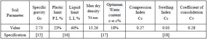
The natural soft soil used in this study is brought from Basra government near sport city complex in the south of Iraq, obtained from a depth of (1 to 1.5 m) below natural ground level after cleaning the top soil surface. The design criteria for selecting a suitable backfill material are availability, suitability and economy. The granular material used as backfill material selecting as criteria define by [8] who defined a suitability number for vibroflotation backfills that is given by Equation (1).Brown's suitability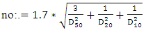 | (1) |
where D50, D20, D10 are in mm at 50, 20 and 10 % passing by weight, corresponding suitability numbers and backfill ratings are given in Table (1), so the granular column D50= 0.75 mm, D20= 0.28mm, D10= 0.2 mm, and corresponding Brown's suitability no=11.14, good rating. The particle size distribution (sieve analysis) of the granular material are determined using standard methods for coarse-grained soils (i.e. particles having diameter > 0.074 mm) according to, [9]. For soft soil, fine-grained soils (i.e. particles having diameter ≤0.074 mm, Hydrometer analysis was performed according to [10], where the soft soil and the granular material is classified as (silty clay), and (sand with some granular), respectively according to MIT classified system [11]. The particle size distribution is shown in Figure (1). The granular material has a specific gravity of 2.65. The maximum, minimum dry densities, which were determined according to [12, 13] respectively, were 18.9 kN/m3, 16.5 kN/m3, respectively.Table 1. Brown’s suitability Numbers
 |
| |
|
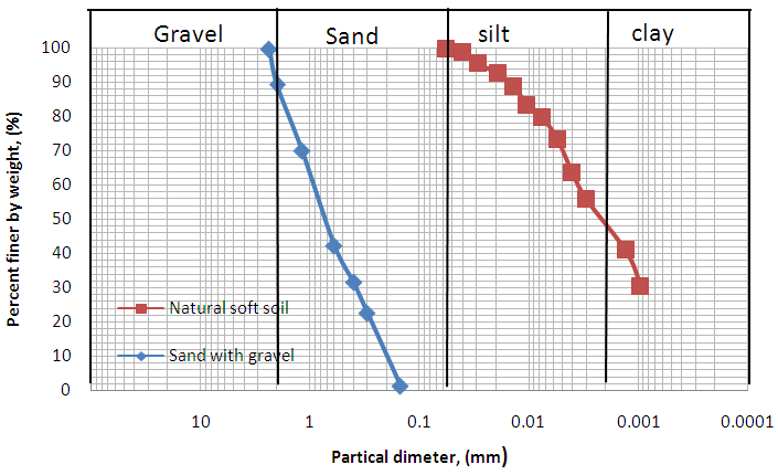 | Figure 1. Grain Size Distribution of the Natural Soil and Granular Material Used (Based on MIT Classified) |
2.2. Properties of Soft Soil
The natural cohesive soil specimen crushed with rubber pestle to make it uniform as possible and then free-fall procedure for soil sample proposed by [14] was used to ensure that small soil lumps of the soil specimens were broken up consistently. The soil specimen was oven- dried for 24 hour then the soil particles dry sieved from (Sieve No. #4) and the retain soil on sieve (i.e. particles larger than 4.75 mm were (1 to 2%) by weight) disposed to avoid using large soil particles in testing. The soil was then divided into (500g) specimens contained in a plastic bag. The geotechnical soil properties are presented in Table (2).Table 2. The geotechnical cohesive soft soil properties
 |
| |
|
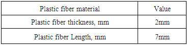
2.3. Plastic Fiber Material
In the present study, plastic fibers were used as reinforcement material mixed with granular column abbreviated as (FGC). The fibers piece cut to the desired lengths according to the requirements for study. The plastic fiber materials were used with a proportion 4% mixed with 96% granular material. Table (3) illustrates properties of plastic fiber material. Figure (2) show the shape of plastic fiber material used in the study.Table (3). Dimensions of Plastic Fiber Material
 |
| |
|
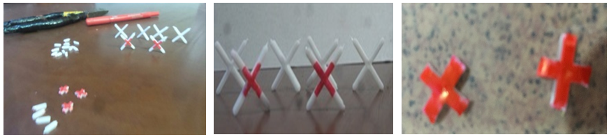 | Figure 2. Plastic Fiber Material Used in reinforced granular column (FGC) |
2.4. Preparation of Soil Specimen for Triaxial Test
The soil passing sieve (No.10#) was used in testing program, test specimen of 38 mm in diameter and 76 mm in average height were prepared according to [19]. The moisture content (20%) and dry unit weight (15.2 KN/m3) were selected for, preparation soft soil, the soil mixed well with sufficient water to produce the desired water content for 3 minutes to achieve sample uniformity. Then specimens are sealed inside a plastic bag and laid in a covered container for at least 16 hours prior to tamp. The soil specimen was divided into three layers: each layer is determined by weight to achieve that density; the top of each layer shall be scarified prior to the addition of material for the next layer, to achieve the similar volume of the soil inside a split mold. And then the soil tamping in three layers using a steel tamping rod (33 mm in diameter, and weight 450 gm) dropped from a height of (19) cm a for each soft soil layers, after complete tamping of the last layer of the specimen ready to prepare the granular column. A thin coat of grease was applied along the inner surface of the spilt mold.
2.5. Preparation of Granular Column
Granular material (96% sand with some gravel mixed with 4% plastic fiber) was constructed by replacement method. The position of the granular column must be placed correctly in the center of the specimen by using a special plate having a hole in the middle. Figure (3) shows the mold used in the study. Granular material was mixed with desired water (8%) after that the granular material ready to prepare the granular column in the soil specimen. A thin hollow open-ended steel pipe of (12 mm) outer diameter and wall thickness (2 mm), a thin coat of grease was applied on the on the outer surface of the pipe for easy penetration and withdrawal without any significant distribution to the surrounding soil), after that the pipe was placed in a special plate were pushed vertically to the required depth, after locate accurately at the center of the split mold. The pipe was then slowly withdrawn and twisted during the lifting process. A pipe was then inserted in the hole to charge granular material into the hole in layers, light compaction was given with a steel tamper (that achieve required relative density, Dr=65%) after placing granular material by the specified weight for the layer the pipe was then raised in stages to ensure minimum (5 mm) penetration below the top level of the placed granular material (to prevented cavity of the clay form surrounding into the hole). The procedure was repeated until the column form to the full height. Special care was taken during construction to maintained uniform diameter along the length of the column, and then the specimen was equipped for tested in triaxial test. Figure (3) shows the method of installation granular column carried out in experiential.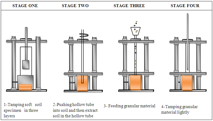 | Figure 3. Vibro-Replacement Granular Column Technique carried out in experiential work for Triaxial Test |
3. Test Results
3.1. Unconfined Compression Test
The unconfined compression test (UCS) is a special case of unconsolidated undrained triaxial test carried according to the [20]. This test is basically used to find the shear strength (C) of the composite specimens from unconfined compression strength (qu). Tests were conducted to determine the shear strength parameters of ordinary granular column OGC (filling material, is sand with some gravel) and granular column mixed with plastic fiber material FGC, with two shapes (A, and B shapes) with percentage of mixing (4, 8, and 12%) was used. These tests are considered as a reference for the ongoing triaxial testing program. The triaxial machine strain rate (1mm/minute) was selected. The specimen are 38 mm in diameter and 76 mm in height, and the granular column with ratio of(L/d=5.4) and ar=13%. The test results of (UCS) are shown in Figure (4) that illustrates the stress-strain behavior of composite specimens. Initially the stress gradually increases with the increasing the strain, after attaining the peak stress, it decreases with increasing in strain for all the composite specimens. The results of these tests have been found that the higher shear stress at failure gained at lower fiber content 4% (A shape).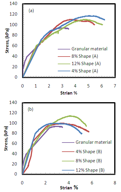 | Figure 4. Stress vs. axial strain with two shape of fiber material: (a) A shape, and (b) B Shape |
3.2. Triaxial Test
The experimental program included 21 tests, the prepared sample set in triaxial cell, and sheared at rate of 0.09 mm/min. Tests comprised the following steps:Step 1: The specimen is subjected to full saturation (by check Skempton coefficient B >, 95%, define as B = Δu/Δσ3). Step 2: The specimen is subjected to isotropic consolidation, under confining pressures of σ3 (100, 200, and 300 kPa). Step 3: Shear stage is applied at constant confining pressure under undrained conditions with the measured excess pore pressure up to specimen failure.
3.3. Triaxial Compression Test for Unreinforced and Reinforced Clayey Soil by Granular Column with Various (L/d) Ratios
The specimens were prepared and saturated for this series as described earlier. All specimens were consolidated isotropically to the desired mean effective stress (p'). After consolidation, the specimen were subjected to undrained shearing at a strain rate of 0.09 mm/ min over the entire top surface of the specimen, with an assumption that the granular column and the surrounding clay act as a single element, as proposed by the "unit cell" arrangement [21]. Figure (5) show typical results of the triaxial tests carried out on unreinforced and reinforced composite specimens with granular column (OGC) and reinforced granular column with fiber (FGC- A shape) with various (L/d) ratio. The Figure illustrates that the peak stress is not observed. Besides, an increase in the shear strength of the granular column is noticed as (L/d) ratio increase; also deviator stress at failure for FGC is noticed higher than that for OGC.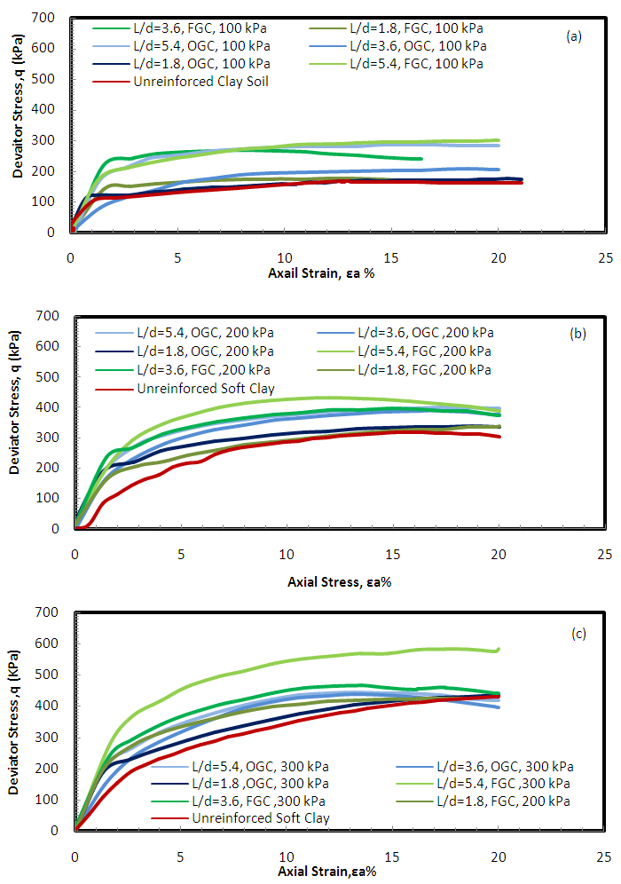 | Figure 5. Deviator Stress vs. Axial Strain for Unreinforced and Reinforced Soil with OGC, and FGC with confining pressure: (a) 100 kPa (b) 200 kPa, and (c) 300 kPa |
Figure (6: a, b) shows the variation of pore water pressure (PWP)/ effective confining pressure  ratio vs. (L/d) ratio for both (FGC and OGC), Figure indicates a decrease in the
  ratio.with an increase (L/d) ratio and confining pressure. This is due to dilation in the granular material during the application of deviator stress.
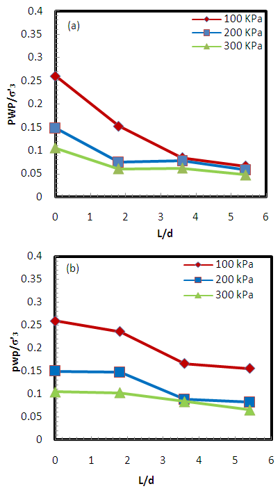 | Figure 6. (PWP /) Ratio vs.(L/d) Ratio for : (a)OGC, and (b) FGC |
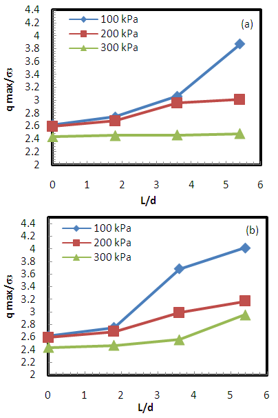
Figure (7: a, b) show relation between maximum pore water pressure (PWPmax) vs. (L/d) ratio. It is noted a clear decrease with increasing (L/d) ratio. Also, it can be observed that PWP increased as confining pressures increased. This value is higher for FGC than that for OGC. Figure (8: a, b) show the relation between  versus (L/d) ratio. The value of
  increase with increasing (L/d) ratio, the Figure also indicates the ratio of
  for FGC is higher than that of OGC. The ratio of
  increased when decreasing the confining pressure. The variation of
  is more pronounced for lower (100 kPa) confining pressure.
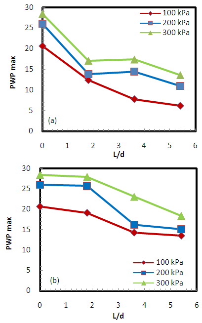 | Figure 7. (PWP max) value vs.(L/d) Ratio for: (a)OGC, and (b) FGC |
 | Figure 8. (qmax/σ3) Ratio vs.(L/d) Ratio for: (a)OGC, and (b) FGC |
Based on the results of CU tests shown in Figure (9) for reinforced and unreinforced specimen, it has been found that CSL moves downward in ν-lnp' plane in term of critical state parameters with the increasing (L/d) ratio. Figure (9) shows the convergence between the ISL line (i.e. initial state line which is referred to the state after isotropic consolidation but just prior to shearing) and the CSL line of the soft clay. The Figure indicates a decrease in the void ratio with increasing confining stress for specimens reinforced with granular column (OGC and FGC) as increasing the (L/d) ratio. The specimens reinforced with OGC gain slightly lower void than in specimens reinforced with FGC.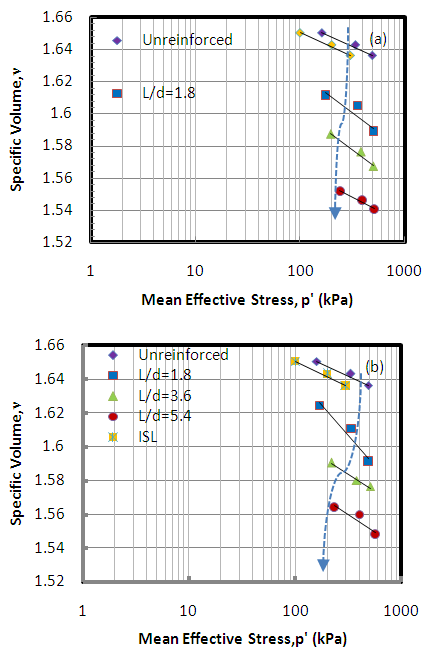 | Figure 9. CSL and ISL for Unreinforced and Reinforced Soil with various (L/d) Ratio with: (a) OGC, and (b) FGC |
Figure (10) shows the plot (q-p') plane for unreinforced and reinforced soil strength envelope at failure for OGC and FGC with various (L/d) ratios. The state of effective stress is characterized by the slope of the critical state line M, which is defined by end point of each test as: | (2) |
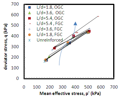 | Figure 10. Strength Improvement Comparison among unreinforced and Reinforced Soil with OGC, and FGC, with various (L/d) Ratio |
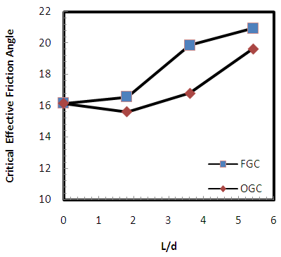
The slope of CSL (M) values observed increases as (L/d) ratio increases. The FGC gain higher values of M than OGC, which show the larger improvement in the shear strength. The calculated effective friction angle  dependson slope (M) as follows:
 | (3) |
The critical friction angle increased from the plane soil condition as (L/d) ratio increasing. The FGC provides higher values of M and  thanthat OGC as shown in Figure (11) and (12) respectively.
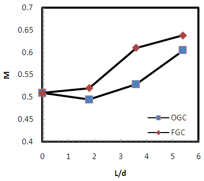 | Figure 11. M vs.(L/d) Ratio for OGC, and FGC |
 | Figure 12.  (L/d) Ratio for OGC, and FGC (L/d) Ratio for OGC, and FGC |
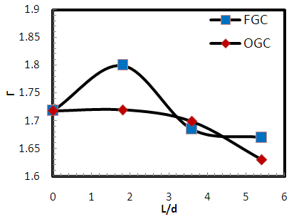
The critical state parameters are described in parameters of (λ, Г, and ξ) to illustrate the critical state of the specimen shown in the equation below: | (4) |
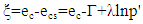 | (5) |
where λ is the slope of CSL, Г is reference mean effective stress which is defined as the specific volume reference mean effective; stress at 1 kPa. Figures (13) to (14) show the variation of λ, and Г with various (L/d) ratios. It can be noticed that the values of (λ, and Г) decreased as the (L/d) ratio increased. 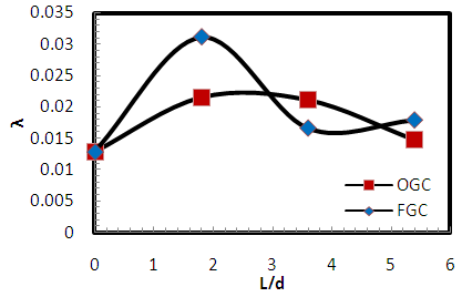 | Figure 13. λ vs. (L/d) Ratio for OGC, and FGC |
 | Figure 14. Г vs. (L/d) Ratio for OGC, and FGC |
Figure (15) shows the relation between state parameter ξ vs.(L/d) ratio. The state parameter (ξ) is defined as a physical parameter to describe the state of soil in ν-lnp' plane with respect to the CSL, in order to determine the difference between the current void ratio at the end of consolidation (ec) and the void ratio at critical state  at the same mean effective stress on critical state concept. The state parameter values increased with increasing the stiffness along with the increasing (L/d) ratio. In case of reinforced soil with FGC, it can also be noticed that no more difference is found in increasing the state parameter for both (L/d= 3.6, and 5.4). So, it is economically in (FGC) to stop the column at (L/d=3.6) (i.e. floating phase) not in end bearing (L/d=5.4) as in (OGC).
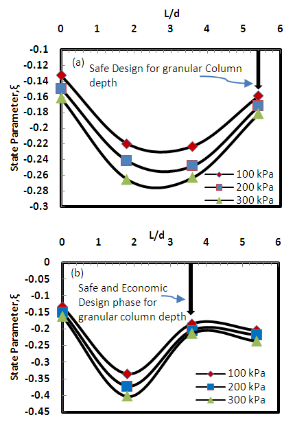 | Figure 15. ξ vs. (L/d) Ratio with: (a)OGC, and (b) FGC |
4. Conclusions
The following conclusions can be listed from the study:1) Increasing in the shear strength of the granular column is noticed as (L/d) ratio increases, and also observed the deviator stress at failure for FGC is noticed higher than that for OGC.2) The stress ratio M, and critical effective friction angle  at CSL increases with (L/d) ratio increase. The FGC provides higher values of M and
  than that OGC, indicates larger improvement in shear strength.3) The excess pore water pressure decreased as increasing (L/d) ratio. The peak pore pressure decreased more at higher confining pressure and when the columns length increases. The
  ratio decreaseg as increasing (L/d) ratio and confining pressure. Also noticed that the excess pore water pressure generated in FGC is higher than that in OGC.4) In the plots of q-p' plane, the CSL has a unique line for each case of reinforcing sample and indicating improvement in the shear strength (i.e. increase in the deviator stress).5) The specimens reinforced with OGC gain slightly lower void than in specimens reinforced with FGC.6) The importance evidence of this study for geotechnical design is the state parameter behaviour (ξ), which gave a good indication and possibility of the reducing the length of granular column for design purposes the case of (floating-FGC) when compared with (end bearing- OGC) behaviour.Based on model scale of the study and test results data, the importance evidence of this study for geotechnical design purposes is the state parameter behavior (ξ), which gave a good indication for safe and economic design for FGC depth (i.e. with floating FGC, L/d=3.6), instead of safe design for OGC depth (i.e. with end bearing OGC, L/d=5.4). Care should be taken for large real case problems to verify that criteria.
References
| [1] | Wang, G. (2009). Consolidation of soft soil foundations reinforced by stone columns under time dependantloading., Journal of Geotechnical and Geoenvironmental Engineering, 135(12), pp.1922-1931. |
| [2] | Greenwood, D.A. (1970), Mechanical Improvement of Soils below Ground Surface, Conf., Institute of Civil Engineers, June, pp.11-22. |
| [3] | Ala'a Hussein Alwan Al-Zuhairi. (2000) The use of sand columns to improve soft soil, College of Engineering of The university of Bagdad. |
| [4] | Mukul and Chandra Bora, (2014), Laboratory Determination of Critical State Parameters of Stone Column. |
| [5] | Wu, C. S, Hong, Y. S. (2008), The Behavior of a Laminated Reinforced Granular Column, Geotextiles and Geomembranes Vol.26, pp. 302–316. |
| [6] | Basu, P. (2009), Behavior of sand-fiber mixed granular piles, PhD Thesis, Indian Institute of Technology Roorkee, Roorkee, India. |
| [7] | Rakesh, K., and Jain P.K., (2013), Soft ground improvement with fibre reinforced granular pile. Int. Jrnl. of Advanced Engineering Research and Studies, 2(3), pp. 42-45. |
| [8] | Brown R. E., (1977), Vibrofloatation compaction of cohesionless soils. J. Geotech. Eng Div, ASCE 103(12):1437–1451 |
| [9] | ASTM D421, Standard Practice for Dr. Preparation of Soil Samples for Particle-Size Analysis and Determination of Soil Constants, American Society for Testing and Materials. |
| [10] | ASTM D422-2001, Standard Test Method for Particle Size-Analysis of Soils, American Society for Testing and Materials. |
| [11] | Massachusetts Institute of Technology (M.I.T) Soil Classification System. |
| [12] | ASTM D4253-2000, Standard Test Method for Maximum Index Density and Unit Weight of Soils Using a Vibratory Table, American Society for Testing and Materials. |
| [13] | ASTM D4254-2000, Standard Test Method for Minimum Index Density and Unit Weight of Soils and Calculation of Relative Density, American Society for Testing and Materials. |
| [14] | Japanese Society of Soil Mechanics and Foundation Engineering, JSSMFE (1982), Soil testing methods, 2nd revised Ed. Japan. |
| [15] | ASTM D 854-00: "Standard Test Method for Specific Gravity of Soil Solids by Pycnometer", American Society for Testing and Materials. |
| [16] | ASTM D 4318-00, "Standard Test Methods for Liquid Limit, Plastic Limit, and Plasticity Index of Soils", American Society for Testing and Materials. |
| [17] | ASTM D-698, Standard Test Methods for Laboratory Compaction Characteristics of Soil Using Standard Effort (12 400 ft-lbf/ft3 (600 kN-m/m3)), American Society for Testing and Materials. |
| [18] | ASTM D-2435, Standard Test Methods for One-Dimensional Consolidation Properties of Soils Using Incremental Loading, American Society for Testing and Materials. |
| [19] | ASTM-D4767-04, Standard Test Method for Consolidated Undrained Triaxial Compression Test for Cohesive Soils, American Society for Testing and Materials. |
| [20] | ASTM D2166-00, Standard Test Method for Unconfined Compressive Strength of Cohesive Soil, American Society for Testing and Materials. |
| [21] | Balaam, N.P., Poulos H.G., and Brown P.T. (1977), Settlement Analysis of Soft Clays Reinforced with Granular Pile, Proc. 5th SEAGC, Bangkok, pp. 81-92. |

 Abstract
 Reference
 Full-Text PDF
 Full-text HTML