Journal of Civil Engineering Research

p-ISSN: 2163-2316    e-ISSN: 2163-2340

2015;  5(6): 162-171

doi:10.5923/j.jce.20150506.06


Simplified Nonlinear Analysis of Reinforced Concrete Slabs and Beams

Graham Dean Roberts1, Kuinian Li2

1Dams & Hydro, ARQ Consulting Engineers, Pretoria, South Africa

2School of Civil & Environmental Engineering, University of Witwatersrand, Johannesburg, South Africa

Correspondence to: Graham Dean Roberts, Dams & Hydro, ARQ Consulting Engineers, Pretoria, South Africa.

Email:

Copyright © 2015 Scientific & Academic Publishing. All Rights Reserved.

This work is licensed under the Creative Commons Attribution International License (CC BY).
http://creativecommons.org/licenses/by/4.0/

Abstract

The use of the finite element method in the design of reinforced concrete slabs and beams has become a generally accepted practice in recent times and when designing structural members, both ultimate and serviceability limit states are required to be considered in the consequent analyses. This paper presents a simplified method to the nonlinear analysis of reinforced concrete slabs and beams for serviceability and ultimate limit states. The method allows for the use of simple design equations familiar to all structural engineers undertaking reinforced concrete designs. Using the finite element method, plate elements and simplified constitutive properties, a nonlinear algorithm is developed which results in the accurate estimation of the displacements during loading as well as a design ultimate loading. The proposed model and nonlinear algorithm is validated and verified against three experimental case studies which show the accuracy and relevance of the given nonlinear solution. The model and algorithm presented can be easily integrated into a commercial finite element package for use in the design of reinforced concrete slabs and beams.

Keywords: Nonlinear, Reinforced Concrete, Simplified, Finite Element Method, Design

Cite this paper: Graham Dean Roberts, Kuinian Li, Simplified Nonlinear Analysis of Reinforced Concrete Slabs and Beams, Journal of Civil Engineering Research, Vol. 5 No. 6, 2015, pp. 162-171. doi: 10.5923/j.jce.20150506.06.

1. Introduction

The finite element method is widely used in modern day reinforced concrete slab and beam design using either plate or shell elements to represent the structural behaviour. Many commercial finite element software packages have design code checks to allow for the elastic analysis and design to be carried out using one software package. For certain packages a design code based approach to moment redistribution and serviceability deflection checks could be included.
It is however not common for the standard finite element packages to carry out a more accurate numerical nonlinear analysis to account for moment redistribution and accurate serviceability deflection checks.
The nonlinear behaviour of reinforced concrete is complex in nature and has been under consideration since mid-1960 through till today. The formulation of plate and shell elements began to be established in early 1960 and formulations improved rapidly through till late 1980. The evolution of both topics have taken place over a similar period and with the increase in computing power over the late 1980 early 1990 many researchers have developed separate constitutive numerical relations combined with plate and shell element formulations to mimic the nonlinear behaviour of reinforced concrete slabs.
These methods however, such as the layered method given by Hu and Schnobrich (1990) [9], Zhang and Bradford and Gilbert (2007) [26] can be seen as complex to engineers not entirely familiar with the detailed theory of finite elements. Polak (1996) [16], introduced a less complex approach by using an effective Young’s modulus based on the effective moment of inertia equation given by Branson (1968) [5]. The method proposed by Polak allows for serviceability deflection checks only and requires the internal finite element solving procedure to be adjusted by enabling the calculation of an effective moment of inertia using averaged Gauss point moment results at each load step.
This paper presents a simplified design approach to the nonlinear analysis and design of reinforced concrete slabs and beams. The approach allows for standard stress-strain relationships to be established using common reinforced concrete design equations. These stress-strain relations can be defined for each direction of reinforcement and used in the nonlinear analysis as would be done for typical orthotropic ductile materials. The method will allow for the easy implementation into most commercial finite element software packages with Application Programming Interface (API) capability.

2. Theoretical Finite Element Model

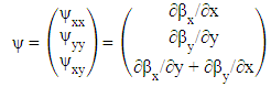
To implement, validate and verify the simplified method of analysis, a finite element code is created, by the author, using MatLab R2011b. Elements are established in the form of 8-noded plate elements based on Mindlin-Reissner [19] [14] [20] formulation with three degrees of freedom per node as given in text by Bathe (1996) [4] and shown in Figure 1.
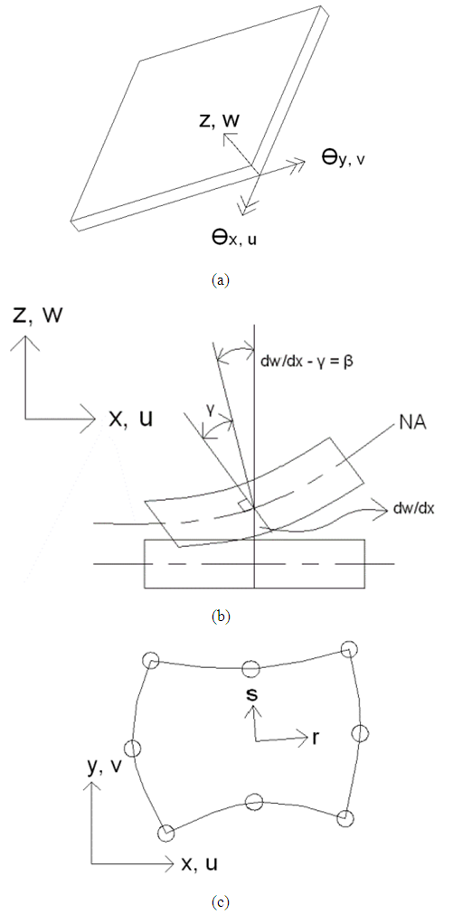
Figure 1. (a) Nodal degrees of freedom (b) Bending & shear deformation (c) Isoparametric 8-noded plate element axis [19] [14] [20]
The three degrees of freedom at each node comprise two rotations and one translation. Rotations are about the two in-plane axes, x and y, and the one translation is in the vertical, z, direction, Figure 1a.
As this form of plate formulation is subject to shear locking, selective reduced integration is employed. Bending stiffness terms are integrated with 3x3 Gauss point integration and shear stiffness terms with 2x2 Gauss point integration.
The resulting formulated element stiffness matrix is given in equation (1). For the shear component of stiffness the commonly used shear correction factor κ = 5/6 is used to adapt the parabolic shear distribution to an equivalent uniform distribution.
(1)
Where:
Ae = Element area
h = Section height
Bb = Strain interpolation matrix for bending
Bs = Strain interpolation matrix for shear
Cb = Bending constitutive material matrix
Cs = Bending constitutive material matrix
ke = Element stiffness matrix
κ = shear correction factor (5/6)
In reinforced concrete slabs the reinforcement may differ in each separate direction of bending according to design. The constitutive material matrices for bending and shear are defined so that each local axis direction, x and y, are assigned independent elastic moduli and Poisson's ratio. The defined bending and shear constitutive material matrices are given in equations (2) and (3) respectively.
(2)
(3)
Shear modulus is given in equation (4).
(4)
It is postulated that by the correct manipulation of the constitutive material matrices, representing the slab stiffness in each reinforcement direction independently, an accurate interpretation of the nonlinear behaviour of the reinforced concrete can be obtained.
The displacement components of co-ordinates x, y and z obtained from the plate element based on small displacement theory are given by equation (5).
(5)
Where:
z = Vertical distance measured from the plate mid-plane
w = Transverse displacement
βx = Rotation in the xz plane
βy = Rotation in the yz plane
Plate curvature is defined by equation (6).
(6)
Plate in-plane and out of plane strains are defined by equations (7) and (8) respectively.
(7)
(8)

3. Material Properties

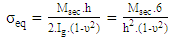
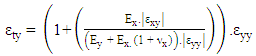
The nonlinear reinforced concrete material constitutive relations are established with two objectives in mind. Firstly the material properties presented must have the required level of accuracy so as to validate its use in design methods and secondly to enable ease of formulation for the design engineer. In the derivation of the nonlinear material properties of the reinforced concrete, with regard to this paper, the following assumptions are made.
Simple beam theory: Cross sections normal to the mid-plane of an element that are plane prior to loading and remain plane during the stress development process. This assumption is made for the formulation of thin plates and as thick plate theory is used in the finite element formulation in this paper, this assumption may affect behaviour. But as the theory is established for use in slab members, shear deformations are not expected to contribute significantly to the overall deformation of an element.
Tension controlled reinforced concrete: Structural elements considered in the scope of this paper are considered to be tension controlled whereby the tensile reinforcement will reach yield strain prior to the onset of concrete compressive failure. This assumption is valid as slab designs should be carried out so as to ensure ductile failure modes. Tension control should in any case be checked in the design process.
Linear strain distribution: Strains throughout the cross sectional depth are assumed to have a linear distribution. This has been shown to be a valid assumption when carrying out the analysis and design of reinforced concrete structures.
Compatible strains: the reinforcement is assumed to have a perfect bond with the surrounding concrete. This is a common assumption in the design of reinforced concrete slabs.
The nonlinear behaviour of reinforced concrete can be effectively depicted using the standard moment curvature relations and bending stiffness is therefore dependent on the slope of the moment curvature graph, 
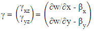
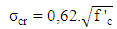
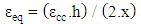
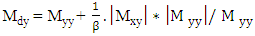
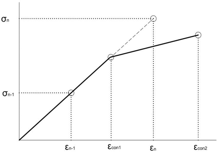
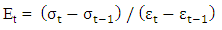
. When the section is loaded and as loading increases, the concrete in tension reaches the cracking strain and with increased loading cracking is initiated and propagation continues upward till the yielding and ultimate moments are reached.
As the crack propagates upward, the section I value and therefore bending stiffness continues to change throughout the loading process. Through experimentation Branson (1968) [5] developed an equation to calculate the effective I value of a reinforced concrete beam and would enable the efficient calculation of section deflection and can be used to manually calculate deflections in structural systems.
When carrying out the finite element analysis it is not practical to change the h value, as given in equation (1), which directly changes the I value of the section. It is more convenient and common to manipulate the bending stiffness through the changing of the E-modulus.
The question then arises as to which stiffness states to consider. The three major states of moment capacity in a reinforced concrete section can be considered as the cracking moment, yielding moment and the ultimate moment.
The E-modulus is defined as the tangent of a stress-strain relation. As the variation in bending stiffness will be manipulated using the E-modulus and the E-modulus is dependent on the relation of stress and strain, an equivalent stress-strain graph will be constructed to represent this variation in bending stiffness of the reinforced concrete section as shown in Figure 2.
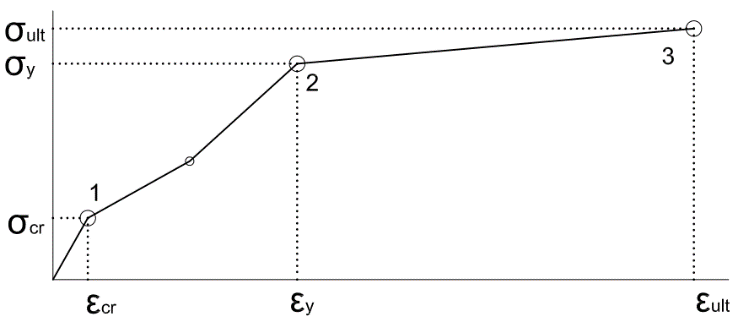
Figure 2. Typical equivalent stress-strain graph
The first point of the stress-strain graph can be calculated as per normal using the modulus of rupture as the calculated stress point and the strain calculated using the section concrete E-modulus, assuming a low reinforcement ratio, and is given in equations (9) and (10) respectively.
(9)
(10)
To correctly represent the remaining two design moment capacity strain states, it is required that they be transformed into equivalent finite element moment capacity strain states. Figure 3 shows a typical design strain state as would be defined by any particular design code and also what could be expected using finite element analysis. Through simple equations an equivalent strain and stress can be associated with actual design moment and curvature.
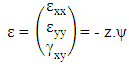
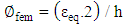
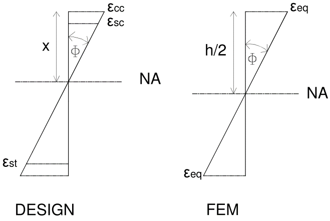
Figure 3. Design strain state and equivalent finite element strain state
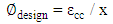
Design curvature of the reinforced concrete section may be calculated using equation (11).
(11)
Curvature for the finite element program can be assessed using equation (12)
(12)
To ensure curvature compatibility between the finite element program and design behaviour equations (11) and (12) are equated giving rise to equation (13) which is used to calculate the equivalent strain point (εeq) on a typical stress-strain diagram, Figure 2.
(13)
Now the section moment capacities associated with the design strain states used in calculating the equivalent strain points are converted into an expected stress using equation (14).
(14)
Where:
Ig = Second moment of area of the gross cross-section
Msec = Section moment capacity at any given strain state
ν = Poisson’s Ratio
σeq = Equivalent stress at any given strain state
The three main strain states which should be considered in the formulation of a typical stress-strain diagram are shown in Figure 4.
Figure 4. Three major design strain states to be considered
Between the cracking moment and the yielding moment the upward crack propagation has a significant nonlinear effect on the bending stiffness, dependant on reinforcement ratios, and therefore this portion of the stress-strain graph is represented using a bilinear relationship with an intermediate point being defined as the point whereby the curvature is 1/2 that of the yielding moment state.
The proposed method for constructing the typical stress strain diagram is set out in the following steps:
1. Calculate ultimate moment and ensure tension controlled member
2. Calculate Cracking Stress – Point 1
3. Calculate associated Cracking Strain – Point 1
4. Calculate section equilibrium where strain in the tension steel is at yield strain
5. Calculate equivalent strain at yield – Point 2
6. Calculate equivalent stress at yield – Point 2
7. Using information from step 1 calculate equivalent strain at ultimate – Point 3
8. Calculate equivalent stress at ultimate – Point 3
9. Using information from step 4 calculate section equilibrium where curvature = 1/2 of yield called Point 1a
10. Calculate equivalent strain – Point 1a
11. Calculate equivalent stress – Point 1a
All of the above can be carried out independent of the finite element analysis or built into the program. It is preferable to carry out the calculations prior to the analysis as they serve as a means to ensure that the design engineer has independently carried out the design calculations and is familiar with the expected behaviour of the reinforced section under consideration and can therefore have a better “feel” of what results can be expected from the analysis.
As a simplification, following the initial cracking strain of the concrete the Poisson’s ratio is taken as equal to zero and therefore stress points 1a, 2 and 3 should also be calculated using a Poisson’s ratio of zero.

4. Nonlinear Solver Algorithm

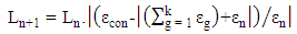
The proposed nonlinear solution considers only material nonlinearities and does not consider geometric nonlinearities as large displacements are not of concern for this particular application.
As discussed in Section 2 the E-modulus of the material can be changed to give an equivalent bending stiffness to the plate formulation. Using the reinforcement properties of the concrete member, what is now termed strain control points making up a typical stress strain diagram can be established. This is assuming that the local x and y co-ordinates of the plate elements are aligned with the two directions of reinforcement and local co-ordinates results are used to assess nonlinearity.
The overall solution is a nonlinear analysis, but the intermediate solution procedure is in essence a repetitive linear static solution updating the stiffness matrix after each converged load step. A converged load step is defined as one in which the applied loading at a given increment causes no strain at any one result point to exceed criteria and one or more to fall within the convergence criteria. For this procedure the convergence criteria is defined by equation (15) as given by Roberts (2014) [21].
(15)
Where εcon is controlling strain point given by points making up the graph in Figure 2 and εg is the cumulative calculated strain for all previous converged load steps, (k), and εn is current iteration calculated strain. Considering equation (15) cannot be completely satisfied due to rounding off errors or formulated strain failure criteria equation, an acceptance error chosen by the user but defaulted to 1.0% for this paper is employed.
If one assesses a pure one way spanning system only moments in the bending direction are to be evaluated, but for a two way spanning system the twisting moments are required to be considered. Methods established by Wood and Armer (1968) [25] allow for the accounting of the twisting moments in the design. Using this theory as a basis, similar design equations have been be established for the x and y directions independently and are given in equations (16) and (17) with β taken as unity. These equations are only suitable for reinforcement arrangements which are orthogonal in the x and y directions.
(16)
(17)
The design strain quantities associated with the design moment equations are required for the correct implementation of the proposed algorithm. The design strain quantities are calculated by assessing the moment contribution of each stress component to the design moments. The strain components producing the relevant stresses are then determined and defined in terms of the design strain x and y directions.
Using this as a principle, equations (18) and (19) are established for the x and y directions respectively as given by Roberts (2014) [21].
(18)
(19)
Following the cracking and under the assumption of a cracked Poisson’s ratio equal to zero equations (18) and (19) reduce to equations (20) and (21) respectively.
(20)
(21)
Should any point in the system fall below -0.01 using the convergence criteria given in equation (15) it can be seen that one or more strain control points have been exceeded and load reduction would be required to take place. Should no points in the system fall below 0.01 using the convergence criteria it can be seen that the load is required to be increased.
The load increment can be increased / reduced and a new loading magnitude assigned by using equation (22) with variables clarified using Figure 5.
(22)
Figure 5. Load increase / reduction logic
For this paper the check is to be carried out for all elements at each Gauss point in the local x and y directions. From checking the strain limits at Gauss points and if one or more of these points have passed convergence requirements, all required results using converged strains can be calculated and saved for the current load step, Ln. Following the saving of the incremental results, the new modified E-modulus must be assigned for each of the Gauss points within convergence limits or equal to strain limits as dictated by the input stress-strain graph. The modified E-modulus can be calculated using equation (23).
(23)
Where t is the number of the control points given in the calculated input stress-strain graph. All required E-moduli values are calculated prior to analysis, the element stiffness matrices can be reformulated and global stiffness matrix reassembled. For smaller systems, the total global stiffness matrix is reformulated at little computational cost. The nonlinear algorithm is summarised in Figure 6.
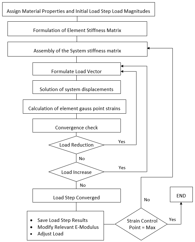
Figure 6. Nonlinear algorithm

5. Experimental Cases

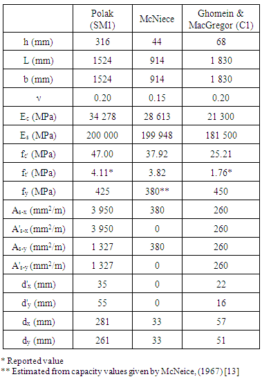
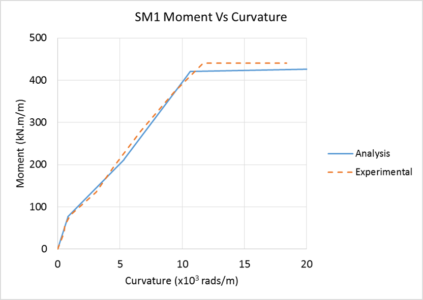
To evaluate the appropriateness of the proposed method, three experimental test cases were evaluated. Firstly an experiment carried out by Polak and Vecchio (1994) [18] for test specimen SM1 was considered. In the experiment a one-way spanning slab was subjected to an increasing edge moment loading in one direction only, Figure 7(a). During the experiment cracking was reported at an applied moment of 75 kN.m/m with first yielding at a moment of 440 kN.m/m and the testing stopped at moment of 464 kN.m/m due to excessive deflections. Moment curvature results were established and are used for the current evaluation.
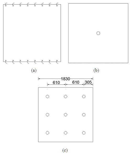
Figure 7. Loading configuration (a) Polak and Vecchio (1994), SM1 (b) McNeice (1967) (c) Ghomein and MacGregor (1992), C1
The second experimental test case is that of a two-way spanning slab tested by McNeice (1967) [13]. The experiment comprised a slab simply supported at each corner and subjected to a point load in the centre of the slab, Figure 7(b). As the point load magnitude was increased, deflection measurements were taken at four different points of the slab. It is noted that the measurements were taken prior to the onset of yielding. A displacement comparison was carried out at node 6, Figure 8. The cracking pattern at the end of elastic behaviour was also compared to that of the current model to assess the accuracy of the yielding pattern and range thereof.
The final experimental test case is that of a two-way spanning slab, specimen C1, tested by Ghomein and MacGregor (1992) [8]. The slab was simply supported along all four edges with uniformly distributed loading being simulated using nine concentrated loads over the slab surface as shown in Figure 7(c). Cracking was first observed at a load of 9.1 kPa. Fully developed yield lines were predicted to occur at a loading of 42.8 kPa. The fully developed yield lines predictions were based on a 0.2% offset yield neglecting the effects of corner levers. It was reported that although the yield lines were present, load carrying capacity was not inhibited. The increase in load carrying capacity was seen to be attributed to an increase in combined bending and tensile membrane actions.

6. Numerical Analysis

The numerical analyses were carried out using 8-noded plate elements as described in Section 2. The SM1 slab was analysed using one plate element simply supported at the ends and edge moment loading applied.
The McNeice and C1 slabs were analysed using an upper right quarter symmetry model discretised using nine plate elements as shown in Figure 8. For the McNeice slab the centre loading was represented by a single out of plain nodal load applied to node 7 and vertically restrained at node 34. For the slab C1 the loading was represented by applying out of plain proportional nodal load at nodes 3, 7, 25 and 29. Slab C1 was modelled as simply supported along the sides of non-symmetry.
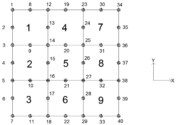
Figure 8. Discretisation of McNeice and C1 slabs
A summary of the material properties used in the finite element analyses is given in Table 1. It is noted that for this paper, moment section capacities were calculated based on previsions given in ACI 318M-05 [1], although a steel stress greater than that of yield is used for the calculation of ultimate section moment capacity. The tensile strength of the concrete is ignored as per design assumptions. Therefore the tension in the concrete does not contribute to section moment capacity nor to stiffness calculations.
Table 1. Experimental Model Material Properties
     
All input parameters given in Table 1 are as per the South African code of practice, SANS-10100: The structural use of concrete: Part 1: Design.

7. Analysis Results

Following the analysis of the SM1 slab the moment and curvature results are extracted, Figure 9. Initial cracking occurred at a moment of 77 kN.m/m with the yielding moment at 425 kN.m/m. From the analysis the section ultimate moment was observed at 457 kN.m/m. Curvatures are seen to be accurate throughout the analysis. The analytical model continues to take loading until the design ultimate moment capacity, as per design equations, was reached.
Figure 9. SM1 Moment vs Curvature
The McNeice slab point load magnitude and vertical nodal translation at node 6 is given in Figure 10. Significant initial cracking was seen to have occurred at a point load of 5.30 kN with ultimate loading being reached at 22.40 kN. Elastic behaviour was seen to end at a loading of 11.60 kN which corresponds to a stiffness state in the slab as shown in Figure 11.
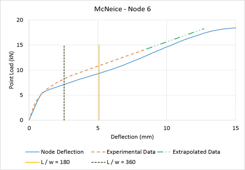
Figure 10. McNeice Node 6 Load vs Displacement
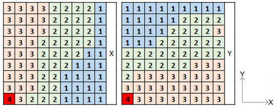
Figure 11. McNeice slab cracking in the x and y directions
Displacement accuracy was assessed at points where L/w equals 180 and 360. In both cases the analytical model predicted these points at a loading 12% lower than that of the experiment. The theoretical model therefore exhibited a less stiff behaviour to that of the experiment. At higher loading, the theoretical model predicts the displacements of the McNeice slab more closely.
Another aspect which was evaluated is the extent of and pattern of yield line development. McNeice established a sketch of the crack pattern at the end of elastic behaviour where the ratio of loading to predicted ultimate loading was 0.56. This sketch was compared to the current model at the end of elastic behaviour which was through this study calculated at a loading to ultimate loading ratio equal to 0.52.
As each of the Gauss points was given a unique equivalent E-modulus, the cracking pattern can be established by inspecting the equivalent E-modulus at the end of elastic behaviour. A value of 1 indicates to E-modulus defined by points 0 and 1 on the typical stress-strain graph, a value of 2 therefore indicates an E-modulus defined by points 1 and 1a on the typical stress-strain graph. Figure 11 gives the equivalent E-modulus for Gauss points in the slab in the x and y directions respectively.
Figure 12 is formulated by superimposing the crack patterns in the x and y directions and comparing this to the observed crack pattern established by McNeice and given in Figure 5.1 of reference [13].
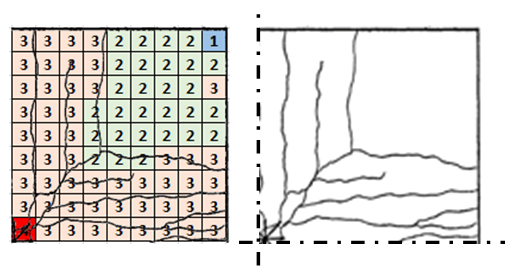
Figure 12. McNeice crack pattern comparison
As can be seen in figure 12, the cracking pattern and extent of cracking at the end of elastic behaviour in the x and y directions is seen to be accurate when compared to the McNeice experiment.
The C1 slab experimentation was carried out only to onset of possible failure with the C1 slab analysis producing interesting but expected results which require further explanation.
Two analyses were carried out, where the first is carried out by considering the section ultimate capacity equal to that of the yield moment capacity for evaluation against predicted yield line load given by Ghomein and MacGregor (1992) [8]. The second analysis was carried out by considering the section ultimate capacity equal to that of the design ultimate moment capacity. Figure 13 shows the load displacement results of the two C1 slab analyses.
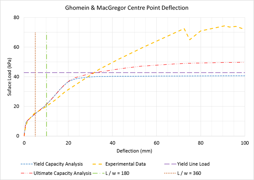
Figure 13. C1 Load vs Displacement
For both analyses the substantial initial cracking and change in stiffness was shown to occur at a loading of approximately 9 kPa. When reviewing the first analysis, loading continued to increase and analytical slab yielding was seen and eventual ultimate yield line loading identified as 40.95 kPa. The predetermined yield line load was calculated as 42.80 kPa which gives a difference of 4.3% when compared with the current model’s results.
When reviewing the results of the second analysis it should be restated that in the C1 slab experimentation it was reported that the load carrying capacity was not inhibited following the reaching of the predicted yield line load due to an increase in combined bending and tensile membrane actions.
The current analytical theory is based on the premise that the system failure mechanism is considered to be section yielding. It is therefore expected that a difference in the predicted ultimate load and actual ultimate load exist. As can be seen in Figure 13 through the analysis the predicted ultimate load was established at 49.5 kPa where the experimental ultimate load was recorded as 73.9 kPa.
Differences in results are considered negligible when considering displacements at serviceability limits of L/w equal to 180 and 360. The current model can therefore be seen as an accurate representation of the experimental behaviour in these ranges.

8. Conclusions

The reinforced concrete slab nonlinear material properties are based on design code calculations. The nonlinear material properties are established for the x and y orthogonal directions of reinforcement independent of one another. Using these quantities typical stress-strain relations are formulated for the use in a nonlinear finite element analysis.
A solution algorithm considering material nonlinearity is presented giving a simple linear finite element program, with API capabilities, the ability to solve the nonlinear problem described in this paper. Although any existing nonlinear algorithm may be utilised for the solution, it should ensure that the updating of the stiffness matrix is carried out using the methods and criteria described in this paper.
Verification and validation was carried out considering three experimental case studies. These experimental case studies ensured that a variety of loading types and boundary conditions are tested against the proposed analytical model. The overall displacement results obtained through the various analyses can be considered sufficiently accurate for serviceability checks under design conditions.
If the design of reinforced concrete slabs is to be carried out assuming ductile yield failure as would usually be done, the proposed model would produce valuable and accurate moment distribution and displacement predictions. The method is however not suitable for forensic structural analysis where actual failure mechanisms are required.
Although results and stiffness values were checked and assigned at element Gauss points independently, a different approach may be followed whereby the Gauss point results are checked and an average element stiffness value calculated and assigned at element level for each direction of reinforcement respectively. This decision would depend on the fineness of the discretisation which should be able to sufficiently represent the distribution of yielding throughout the slab.
Although not considered in this paper, continuous slabs can be seen to be analysed by extending the typical stress-strain graph to include the reinforced concrete slab section negative moment capacities for cracking, yield and ultimate in the same manner as described in the paper. By extending the typical stress-strain diagram any negative moments experienced by the slab, whereby the top of the slab is in tension, can be considered independently and with ease. By using this method accurate moment redistribution results can be established. This should however still be verified with experimental data prior to implementation.
The benefit of the proposed model is that the nonlinear behaviour of a slab is based on a design code approach which closely relates analytical results to the real-life structural system behaviour. The simplified method can therefore easily form part of a design report with engineer’s calculations and not merely a theoretical model built into a finite element program which the design engineer is not fully comfortable with or knowledgeable about.

References

[1]  Agbossou, A and Mougin, J.P. (2005), A layered approach to the non-linear static and dynamic analysis of rectangular reinforced concrete slabs, International Journal of Mechanical Sciences, Vol. 48 No. 3, pg. 294-306.
[2]  American Concrete Institute (2005), Building Code Requirements for Structural Concrete and Commentary, ACI 318M-05.
[3]  Armer, G.S.T (1968), Ultimate Load Tests of Slabs Designed by the Strip Method, ICE Proceedings, Vol. 41 No. 2, pg. 313-331.
[4]  Bathe, K.J (1996), Finite Element Procedures, Prentice Hall, New Jersey.
[5]  Branson, D.E (1968), Design Procedures for Computing Deflections, ACI Journal, Vol. 65 No. 9, pg. 730-742.
[6]  Cerioni R. and Iori I. and Michelini E. and Bernardi P. (2007), Multi-directional modeling of crack pattern in 2D R/C members, Engineering Fracture Mechanics, Vol. 75 No. 3-4, pg. 615-628.
[7]  Ghoniem, M.G and MacGregor J.G (1994), Tests of Reinforced Concrete Plates under Combined Inplane and Lateral Loads, ACI Structural Journal, Vol. 91 No. 1, pg. 19-30.
[8]  Ghoniem, M.G (1992), Strength and Stability of Reinforced Concrete Plates Under Combined Inplane and Lateral Loads, Doctoral Thesis, Department of Civil Engineering, University of Alberta.
[9]  Hu, H.T and Schnobrich, W.C (1991), Nonlinear Finite Element Analysis of Reinforced Concrete Plates and Shells Under Monotonic Loading, Computers and Structures, Vol. 38 No. 5/6, pg. 637-651
[10]  Jofriet, J.C and McNeice, M (1971), Finite Element Analysis of Reinforced Concrete Slabs, Journal of the Structural. Division, Proceedings of the ASCE, ST 3, pg. 785-806.
[11]  Kwak, H.G. and Kim, S.P. (2002), Nonlinear analysis of RC beams based on moment–curvature relation, Computers and Structures, Vol. 80 No.7-8, pg. 615-628.
[12]  Kwon, Y.W and Bang, H (1997), The Finite Element Method using MATLAB, CRC Press.
[13]  McNeice, G. M. (1967), Elastic-Plastic Bending of Plates and Slabs by the Finite Element Method, Partial Fulfilment of The Requirements For The Degree of Doctor of Philosophy, University of London, England
[14]  Mindlin, R.D (1951), Influence of Rotary Inertia and Shear on Flexural Motion of Isotropic Elastic Plates, Journal of Applied Mechanics, Vol. 18, pp. 31-38.
[15]  Myoungsu, S. and Bommer, A. and Deaton, J.B. and Alemdar, B.N. (2009), Twisting Moments in Two-way Slabs, Concrete International, Vol. 31 No. 7, pg. 35.
[16]  Polak, M.A (1996), Effective Stiffness Model for Reinforced Concrete Slabs, Journal of Structural Engineering, Vol. 122 No. 9, pg. 1025 – 1030.
[17]  Polak, M.A (1997), Effective Stiffness Model for Reinforced Concrete Slabs Discussion by A. Bensalem and Closure by Maria Anna Polak, Journal of Structural Engineering, Vol. 123, pg. 1695-1696.
[18]  Polak, M.A and Vecchio, F.J (1994), Reinforced Concrete Shell Elements Subjected to Bending and Membrane Loads, ACI Structural Journal, Vol. 91 No. 3, pg. 261-268.
[19]  Reissner, E (1945), The effect of Transverse Shear Deformation on the Bending of Elastic Plates, Journal of Applied Mechanics, Vol. 67, pp. A69-A77.
[20]  Reissner, E (1975), On Transverse Bending of Plates Including the Effect of Transverse Shear Deformation, International Journal of Solids and Structures, Vol. 11, pp. 569-573.
[21]  Roberts, G.D (2014), Simplified Method to Nonlinear Analysis of Reinforced Concrete in Pure Flexure, Research Report in Partial Fulfillment of Req for the Degree of MSc(Eng), University of Witwatersrand, South Africa.
[22]  Šculac, P. and Jelenic´, G. and Škec, L. (2014), Kinematics of layered reinforced-concrete planar beam finite elements with embedded transversal cracking, International Journal of Solids and Structures, Vol. 51 No.1, pg. 74-92.
[23]  Wight J.K. and MacGregor, J.G. (2012), Reinforced Concrete Mechanics and Design, Sixth Edition, Pearson Education, New Jersey.
[24]  Wood, R.H. and Armer, G.S.T. (1968), The Theory of the Strip Method for Design of Slabs, ICE Proceedings, Vol. 41 No. 2, pg. 285-311.
[25]  Wood, R.H. (1968), The Reinforcement of Slabs in Accordance with a Pre-Determined Field of Moments, Concrete, Vol. 2 No. 2, pg 69-76. (discussion by Armer).
[26]  Zhang, Y.X. and Bradford, M.A. and Gilbert, R.I. (2007), A layered shear-flexural plate/shell element using Timoshenko beam functions for nonlinear analysis of reinforced concrete plates, Finite Elements in Analysis and Design, Vol 43. No.11, pg. 888-900
[27]  Zienkiewicz, O.C. and Taylor R.L. (2005), The Finite Element Method for Solid and Structural Mechanics, Sixth Edition, Butterworth Heinimann.