An Cheng, Huai-Ze Liou, Chia-Hao Lo, Jia-Wei Fan, Shih-Jheng Chen
1, Sec.1, Shennong Road, I-Lan, Taiwan, R.O.C
Correspondence to: An Cheng, 1, Sec.1, Shennong Road, I-Lan, Taiwan, R.O.C.
| Email: |  |
Copyright © 2015 Scientific & Academic Publishing. All Rights Reserved.
Abstract
During the hardening period of conventional concrete, the consumption of water in the hydration reaction of the Portland cement leads to drying shrinkage, which can cause cracking and even failure over the long term. Researchers have recently begun adding conductive admixtures to concrete to monitor its condition according to changes in internal stress, with the aim of self-diagnosis and self-repair. In this study, we replaced a portion of the cement with graphite and explored the relationship between the strain and condition of the concrete according to changes in resistivity. We also conducted ring tests according to the standards in ASTM C1581 in order to allay concerns raised in previous studies related to the influence of fibers on the volume stability of the resulting concrete. Specimens without graphite served as a control group. We employed a water/cement ratio of 0.4, and replaced 12% of the cement in the test specimens with graphite. We also experimented with the addition of 0.5% of the total volume of fiber to enhance the ductility of the concrete and hardening characteristics of the graphite concrete. Our results indicate that the addition of graphite can reduce the strain generated during the hardening period and delay cracking, whereas the addition of fiber was shown to increase the resistance of the specimens to cracking strain.
Keywords:
Graphite concrete, Drying shrinkage, Steel ring test, Fiber
Cite this paper: An Cheng, Huai-Ze Liou, Chia-Hao Lo, Jia-Wei Fan, Shih-Jheng Chen, Volume Stability of Graphite Concrete with Kuralon Fiber, Journal of Civil Engineering Research, Vol. 5 No. 5, 2015, pp. 124-128. doi: 10.5923/j.jce.20150505.05.
1. Introduction
Concrete based intelligent materials can perform self-diagnosis and self-repair. According to [1], the extent of internal deterioration of concrete can be determined via self-diagnosis using lead zirconate titanate (PZT) patches installed at the two ends of the concrete, one as a transmitter and one as a receiver. Pre-stressing concrete with nitinol cables has been shown to enhance damping performance. When cracks form in concrete due to external impact or seismic forces, the heating of cables with an electrical current can be used to reduce the width of the cracks, thereby achieving self-repair. According to [2], the resistivity of concrete is generally very high, ranging from 104 Ù to 107 Ù. Concrete is not self-inductive or conductive per se, such that conductive materials are required to evaluate the condition of concrete. Commonly used conductive materials include graphite, carbon fiber, and metal powder or fiber. Experiments have shown that replacing 8% to 16% of the cement with graphite produces relatively good conductivity in concrete.During the process of curing conventional concrete, hydration reactions involving the Portland cement can lead to cracking from drying shrinkage [3]. In large structures that see long-term usage, such as bridges, internal cracking can lead to collapse. In [4], it was indicated that the partial substitution of silica fume and/or metakaolin for cement could reduce drying shrinkage, wherein the extent of this reduction increased with the proportion of cement replaced (Fig. 1). The addition of silica fume can also delay cracking. Silica fume and metakaolin are ultrafine particulate mineral admixtures between 0.1 μm and 7.4 μm in diameter. However, the addition of graphite with an average particle size smaller than 5 μm can affect the volume stability of concrete. In this study, we conducted experiments in accordance with ASTM C1581 standards to determine the degree to which the amount of graphite in these mixtures influences the drying shrinkage of concrete. We then compared our findings with those obtained in the literature.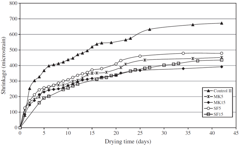 | Figure 1. Effect of silica fume and metakaolin on drying shrinkage of concretes (w/c=0.35) |
2. Experimental Program
2.1. Materials
This study employed Type I Portland cement with a fineness of 3,310 cm2/g. The specific gravity (SSD) and maximum particle size of the coarse aggregate were 2.65 and 19 mm, respectively. The specific gravity (SSD) and fineness modulus (FM) of the fine aggregate were 2.56 and 2.86, respectively. The purity of the graphite exceeded 99.9%, and the average particle size was smaller than 5 μm. We employed Kuralon (K) fibers with a diameter of approximately 0.75 mm, a length of 30 mm, aspect ratio of 40, specific gravity of 1.30, and tensile strength of 1,240 MPa.
2.2. Mix Proportioning
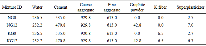
Table 1 lists the mix proportions used in this study. We conducted experiments in which 0% or 12% of the cement volume was replaced with graphite. Considering that the addition of graphite can decrease the strength of the concrete, we used a lower water-cement ratio of 0.4 in order to reach the basic engineering requirements for strength. We also experimented on the addition of 0.5% of the total volume of K fibers to the five mix proportions and compared the results with those produced without the K fibers.Table 1. Mix proportioning of concrete (unit: kg/m3)
 |
| |
|
Specimen numbering:For the first letter, N denotes the mixtures without K fibers, whereas K signifies those with K fibers. The second letter is G, indicating graphite, and the number following it represents the proportion of cement replaced by graphite. Thus, G0 and G12 mean that 0% and 12% of the cement was replaced with graphite, respectively.
2.3. Test Methods
Shrinkage tests in this study were conducted in accordance with ASTM C1581. Dry curing was employed and tests were conducted at a fixed temperature of 22°C and relative humidity of 60%. Figure 2 displays the dimensions of the specimens used for the shrinkage tests.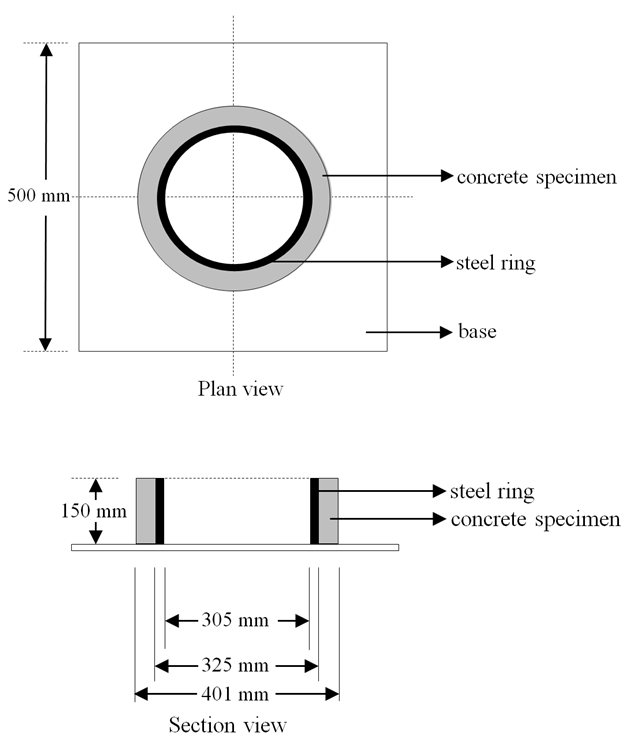 | Figure 2. Ring specimen for shrinkage test |
The test procedure was as follows:Strain gauges were attached to the inner wall of steel ring. A steel ring was bolted to the base with a distance of 38 ± 1.5 mm between the inner and outer rings. Concrete was poured into the space between the inner and outer rings. After clearing away the excess mortar, the top surface of the specimens was covered using plastic wrap for wet curing. After being zeroed, the data acquisition system recorded data every 30 minutes. After 24 hours, the plastic wrap was removed and the bolts loosened before the outer ring was removed from the specimen. The specimens were then coated with paraffin melted on a heating plate to prevent contact with the outside environment during the period of dry curing. When the specimens began cracking, the strain values and curing times were recorded to plot the strain-time curves.
2.4. Calculation
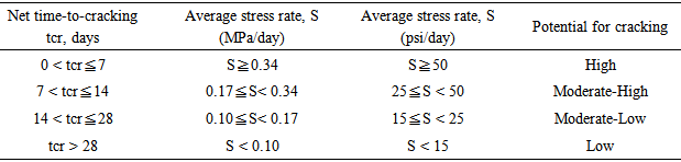
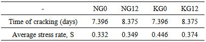
The calculations presented in ASTM C1581 were then to process the strain-time curves and determine the potential for cracking in each specimen.The specimens were then categorized based on time to cracking. Table 2 presents the average stress rates within the various specimens and their potential for cracking.Table 2. Potential for crack classification (ASTM C1581)
 |
| |
|
Plot the net strain (εnet) against the square root of elapsed time for each strain gage on the test specimen and use linear regression to fit a straight line through the data. The strain rate factor (α) is the slope of the line.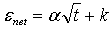 Where:εnet = net strain, m/m [in./in.].α = strain rate factor for each strain gage on the test specimen, (m/m)/day0.5 [(in./in.)/day0.5].t = elapsed time, days.k = regression constant.Calculate the average strain rate factor(α) for each test specimen.
 Where:q = stress rate in each test specimen, MPa/day [psi/day].|αavg| = absolute value of the average strain rate factor for each test specimen, (m/m)/day0.5 [(in./in.)/day0.5].G = 72.2 GPa [10.47*106 psi].tr = elapsed time at cracking or elapsed time when the test is terminated for each test specimen, days.Calculate the average stress rate(S) for each test specimen.
3. Results and Discussions
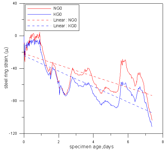
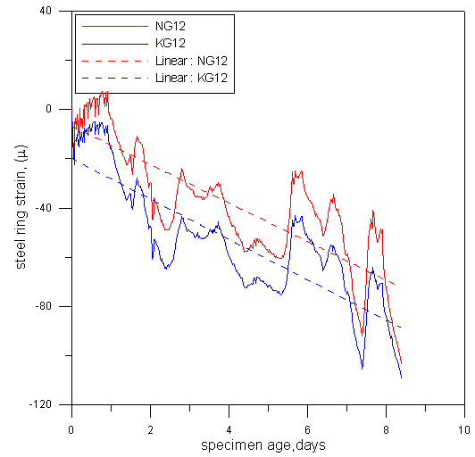
The concrete in which 12% of the cement was replaced with graphite displayed lower shrinkage strain during the hardening period than did normal concrete (Figs. 3 and 4). This supports the results in [4], in which it was shown that replacing cement with finer minerals can reduce drying shrinkage associated with drying. We infer that the substitution of graphite for cement can help to mitigate the hydration reactions by reducing the porosity of the concrete and thereby decreasing shrinkage. Furthermore, we found that replacing 12% of the cement with graphite can delay cracking by a day, which implies that the added graphite may enhance ductility. Figures 5 and 6 indicate that the addition of fibers to normal concrete increases the shrinkage strain. When the amount of graphite was increased from 0% to 12%, the shrinkage strain exceeded that of even normal concrete. This demonstrates that the fibers increase the ductility of concrete as well as its stretchability. If it were possible to enhance the bonding strength between the mortar and fiber, it might be possible to delay the onset of cracking. Table 3 presents the calculation results derived from the strain-time curves based on the data processing methods in ASTM C1581. According to Fig. 7, the time to cracking ranged from 7 days to 14 days. Only the average stress rate (S) of NG0 conformed to the empirical values listed in the standards. The addition of graphite and fiber affected the categorization criteria; i.e., the standards were based on tests on normal concrete, such that the addition of graphite and fiber resulted in the overestimation of average stress rate. Therefore, we used time to cracking to enhance the accuracy of categorization.Table 3. Average stress rate in each specimen(S)
 |
| |
|
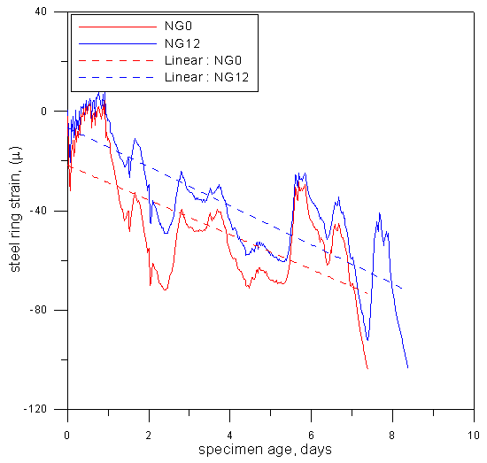 | Figure 3. Effect of graphite on drying shrinkage of normal concrete (w/c=0.4) |
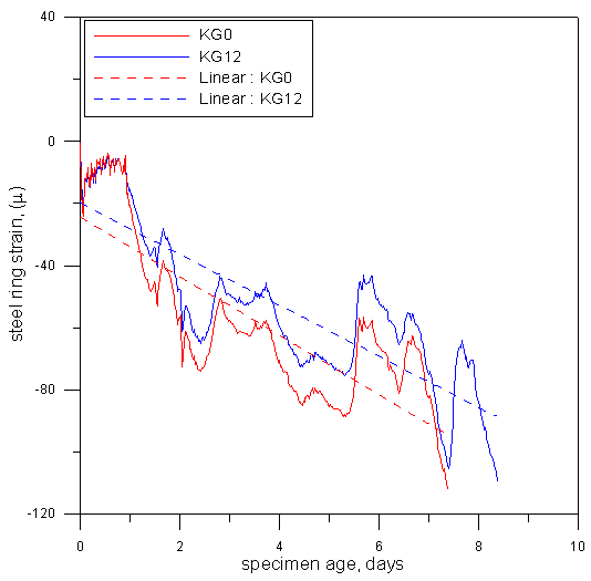 | Figure 4. Effect of graphite on drying shrinkage of fiber concrete (w/c=0.4) |
 | Figure 5. Effect of fiber on drying shrinkage of normal concrete (w/c=0.4) |
 | Figure 6. Effect of fiber on drying shrinkage of graphite concrete (w/c=0.4) |
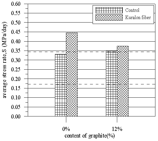 | Figure 7. Effect of control and fiber concrete on average stress rate (w/c=0.4) |
4. Conclusions
Our results demonstrate that concrete containing graphite presents lower strain and longer time to cracking than does normal concrete. This is a clear indication that the addition of graphite increases the volume stability of concrete. If it were possible to enhance the bonding strength between the mortar and the fiber, the ductility of the specimens could also be improved. Nonetheless, the addition of fiber would require adjustments to the mix proportions. The addition of graphite and fiber led to an overestimation of average stress rates; therefore, we surmise that time to cracking is a more accurate criterion for the evaluation of the concrete.
References
| [1] | G Song, YLMo, KOtero and H Gu , Department of Mechanical Engineering, University of Houston, Houston, TX 77204, USA. Department of Civil Engineering, University of Houston, Houston, TX 77204, USA. Health monitoring and rehabilitation of a concrete structure using intelligent materials. Received 24 September 2004, in final form 13 December 2005 Published 30 January 2006. Smart Mater. Struct. 15 (2006) pp.309-314. |
| [2] | Wei-Yuan Dai. Evaluation and Rapid Inspection of Structure Deterioration Using Pressure Sensitive Materials, Master Thesis, National Ilan University, Civil Engineering Department, Taiwan. 2014, pp.1.74-77. |
| [3] | Steven H. Kosmatka, Beatrix Kerkhoff, William C. Panarese. Design and Control of Concrete Mixtures. JIAN JIAO-SHIH, TANG ZU-CYUAN, LU JHONG-YUAN, WANG JHIH, trans. 2005. Chongqing University Press. pp.301-304. |
| [4] | Erhan Guneyisi, Mehmet Gesog˘lu, Seda Karaog˘lu, Kasım Mermerdas. Strength, permeability and shrinkage cracking of silica fume and metakaolin concretes, Gaziantep University, Civil Engineering Department, 27310 Gaziantep, Turkey. Construction and Building Materials 34 (2012) pp.120-130. |
 Abstract
 Reference
 Full-Text PDF
 Full-text HTML