Thuy Ninh Nguyen, Hoang Quoc Vu
Building Materials Lab., Faculty of Civil Engineering, Ho Chi Minh City University of Technology, Viet Nam
Correspondence to: Hoang Quoc Vu, Building Materials Lab., Faculty of Civil Engineering, Ho Chi Minh City University of Technology, Viet Nam.
| Email: |  |
Copyright © 2015 Scientific & Academic Publishing. All Rights Reserved.
Abstract
Up to now, several models of chloride ingress into concrete and cracked concrete have been proposed to simulate the chloride penetration. In the present paper, besides crack widths, crack depths were recognized as a key parameter affecting the chloride penetration depth. A short – term test of chloride diffusion was used to evaluate the influence of crack depths on the chloride penetration depth. By subjecting reinforced concrete beams to bending moments, cracked concrete was generated and investigated as natural cracks. In the field, reinforced concrete structures are under the influence of combined factors such as cracking, loads and marine environment, so in this paper a numerical model was developed and proposed to predict the chloride profile at the crack location of cracked concrete members. In experiments, OPC, Fly ash and Silica-fume concrete were used to verify the proposed model. The comparison between predicted and experimental results showed the fitting well.
Keywords:
Crack, Reinforced concrete, Chloride diffusion, Crack depth
Cite this paper: Thuy Ninh Nguyen, Hoang Quoc Vu, A Simple Approach to Modeling Chloride Diffusion into Cracked Reinforced Concrete Structures, Journal of Civil Engineering Research, Vol. 5 No. 5, 2015, pp. 97-105. doi: 10.5923/j.jce.20150505.01.
1. Introduction
Nowadays, the durability as well as chloride indicted corrosion of reinforced concrete structures in marine environment is very important and becomes serious problems in construction technology. Generally, the chloride could attack the pore structure [1, 2], and was recognized as a main factor leading to corrosion of the reinforcing steel in marine environment [3]. The appearance of cracks due to service load causes the increasing rate of chloride ingress into reinforced concrete structures.Up to now, many researchers have tried to take into account the influence of crack widths on the chloride ingress into concrete structures [4-6]. Besides crack widths, crack lengths are also a key parameter; especially, under loading, the crack depth will rise during all the stages in the life of a concrete structure where it strongly affects the chloride penetration depth. However, the studies on the effects of crack lengths on the chloride penetration are not clear and complete. The chloride penetration in concrete, furthermore, is also under the impact of various loads. [7]. Mien et al investigated to simulate the chloride penetration in plain concrete with invisible cracks under the combined action of cyclic loading and tidal environment [8, 9]. Because of embedding reinforcing steel in real concrete structure, visible cracks often appear and stabilize or rate under varying loads. In addition, in the field there are various factors affecting concrete structures such as natural cracks due to loading and marine environment. Moreover, when the crack occurs in the concrete cover, the rate of chloride ion is accelerated to diffuse into the concrete structure. The chloride profile from the crack tip to inside the concrete varies with the crack depth and becomes the main cause of corrosion of reinforcing steel. Therefore, this study is carried out to investigate the impacts of real crack characteristics, such as crack widths and crack depths, on the chloride penetration in cracked reinforced concrete structures. The migration chloride coefficient [10] will be determined based on the combination of ASTM C1202 and Nordtest NT build 492. A numerical model is proposed to predict the chloride penetration into the cracks of reinforced concrete structures; especially the chloride profile from the crack tip to inside the concrete should be predicted exactly.
2. Development of Model
Generally, it is concluded that the chloride diffusion into the whole crack of concrete must be recognized as two-dimensional diffusion because the diffusion of chloride is not only from the exposed surface to inside the concrete but also through the crack plane exposed to salt solution. However, from the crack tip to inside the uncracked concrete zone, the two-dimensional chloride diffusion should be back the one-dimensional chloride diffusion because the whole crack is closed. With a simple proposed approach for predicting the chloride profile only at the crack location of cracked concrete, the 1D chloride diffusion model based on Fisk’s 2nd Law equation (1) will be proposed | (1) |
For the plain concrete, under coupling cyclic load, the apparent diffusion coefficient of concrete is modified by Mien et al [9] as follows: | (2) |
Where: f4(SR) is a function of the dependence of Dc on the load levels (SR) and is the chloride binding capacity of a cement, which depends on the content component of C3A in cement.The equation (2) is applied to model the chloride penetration in plain concrete under the combination of cyclic load in case invisible cracks appear. However, in the real structure with the embedded steel reinforcement in concrete, the visible crack will occur on the reinforced concrete structure under various loads. Until now, many researchers have concluded that the crack width plays a role in increasing the chloride penetration into cracked concrete. However, in the real reinforced concrete structure under flexural load, the cracks occur on the surface of tension zone and extend from the tension surface to the neutral axis due to the increasing magnitude of loading or number of load cycles. In this research, the crack depth is also considered to have an important role in increasing the depth of chloride penetration, and it is defined as the straight distance from the crack mouth to the crack width that is 30 µm. In some previous studies, they have concluded if the crack width is less a threshold value it seldom affects the chloride diffusion. These proposed threshold values are approximately 50 µm [11], 53 µm [12] or 30 µm [13, 14]. Consequently, to evaluate the chloride ingress into visible cracks of concrete structures, the chloride diffusion coefficient (Da) should be modified and developed to become the chloride diffusion coefficient at crack (Dcr) as follows: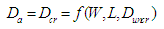 | (3) |
Where: Da, Dcr is a function considering the dependence of Duncr on the crack width (W) and the crack depth (L).Conclusively, the illustration of updated chloride diffusion coefficient of the plain and reinforced concrete with the load can be presented as follows, Figure 1.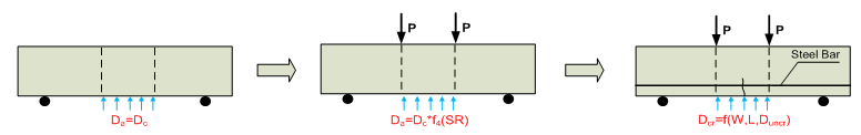 | Figure 1. The illustration of modified chloride diffusion coefficient |
The concept of model development is based on the assumption that chloride will ingress into concrete by penetrating through the whole cracks, then diffusing into the uncracked concrete zones at the crack tip, Figure 2. Firstly, the chloride will diffuse through the cracks and is governed by the chloride diffusion coefficient at crack (Dcr), (Figure 2a). Then, the chloride ions continually diffuse into the uncracked concrete zones at the tip of cracks and are governed by the chloride diffusion coefficient at uncracked concrete zones (Dun-eff), (Figure 2b). This chloride diffusion coefficient (Dun-eff) is affected and governed by the crack depth. 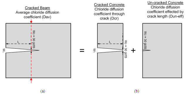 | Figure 2. The concept for chloride diffusion coefficient at crack concrete |
Under the above assumption, the chloride diffusion in cracked concrete is calculated using the equation of Fisk’s 2nd Law in which the proposed average coefficient (Dav) is used: 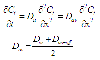 | (4) |
Where: Dcr is calculated based on the crack width (W) following the equation by Djerbi [13] below: | (5) |
However, in their research [13], the crack wall is separated and parallel, but in the real structure and this research, the crack width is reduced with the crack depth. So, the crack width is approximately calculated by the average of crack mouth (W1) and crack width of 30 µm (W2). | (6) |
Where: W1 is crack mount (µm). W2 = 30 (µm).Under the effect of crack depth, the chloride diffusion coefficient of uncracked concrete zone, which is from the crack tip to inside the uncracked concrete zone, will become a function of crack depth, equation (7), and be found out by the experiment program. | (7) |
Where: L (mm) is the crack depth from the tension surface to where the crack width would equal 30 µm (W2); Duncr is the chloride diffusion coefficient of uncracked concrete.
3. Experiment Program
The signification of the experiment procedure is to evaluate the influence of chloride diffusion coefficient of uncracked zone at crack tip (Dun-eff) on the crack depth (L). This correlation is investigated based on the comparison between the chloride concentration depth at uncracked concrete and cracked concrete (Figure 3). This experiment will be based on the short-term diffusion test (STDT) which is modified by combining ASTM C1202 and Nordtest NT build 492 (Figure 4). 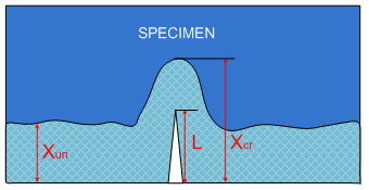 | Figure 3. The concept of the penetration depth at crack location of reinforced concrete |
 | Figure 4. Set up of short-term diffusion test combined by ASTM C1202 and Nordtest NT build 492 |
The concept of this experiment is illustrated on Figure 3, in which xun is the chloride penetration depth of uncracked concrete; L is the crack depth and xcr is the chloride penetration depth at crack tip.Based on Nordtest NT build 492, the chloride diffusion coefficient is calculateded as follows: | (8) |
And: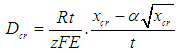 | (9) |
Where: 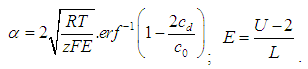 z: absolute value of ion valence, for chloride, z = 1; F: Faraday constant, F = 9.648 ×10⁴ J/(V.mol); U: absolute value of the applied voltage, V; R: gas constant, R = 8.314 J/(K.mol); T: average value of the initial and final temperatures in the anolyte solution, K; L: thickness of the specimen, m; t: test duration, seconds; erf–1: inverse of error function; cd: chloride concentration at which the color changes, cd ≈ 0.07 N for OPC concrete; c0: chloride concentration in the catholyte solution, c0 ≈ 2 N.Under the same condition of environment and the concrete properties, the ratio of xcr and xun would be assumed as the linear relation to the crack depth (L). The penetration depth of crack tip concrete (xcr) is expressed by a function of the crack depth (L) and the chloride penetration depth at uncracked concrete (xun).Moreover, if the crack depth equals zero (no crack) as the boundary condition, the xcr will equal xuncr. Consequently, the penetration depth of crack tip concrete (xcr) is computed by the following equation:
 | (10) |
Similarly, we have: | (11) |
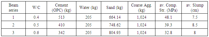
Where: a, a1 - are the experiment coefficient; L is the crack depth from the exposed surface to the crack tip. Conclusively, with the equation (11), the chloride diffusion coefficient at crack (Dcr) would be predicted by the chloride diffusion coefficient of uncracked concrete (Dun) and crack depth (L). In this study, three types of water to cement ratio (W/C) of concrete properties investigated are 0.4, 0.5, and 0.6. The concrete proportions used to study are presented in Table 1. The sand and coarse aggregate were washed and dried before casted to clear their initial chloride content.Table 1. Mix proportion per one cubic meter of concrete
 |
| |
|
After casted with size of 100x100x500, these beam specimens were cured in the mould for one day. After released from the mould, they were continually cured in the tap water for 27 days. Then, single cracks on the beam were generated by the bending test with three-point load; the crack depth was varied by changing the magnitude of applied loads. The cubic specimens containing the cracks were sawn from the cracked beams. Before the chloride diffusion test was used, the crack depth and crack width of cubic specimens were measured by rule and digital microscope. Due to the complicated tortuosity of the crack plane, it is very difficult to determine where the crack tip is by eye. Therefore, in this study, the respective crack depth instead of crack depth would be proposed to survey and it was measured from the tension surface to where the crack width would equal 30 µm.The chloride ion migration into these cracked cubic specimens was tested by STDT which was modified half-cell from cylinder specimens to cubic specimens. The applied voltage for testing was 60 V and the duration of testing was 10 hours. After tested by STDT, the cracked cubic specimens were split along the crack plane into two parts. The silver nitrate 0.1 M was then sprayed on the split surface of the concrete. After 15 minutes, the chloride penetration depth was measured as visible white precipitation of silver chloride appeared at crack tip (xcr). The procedure of the STDT test is illustrated in Figure 5. 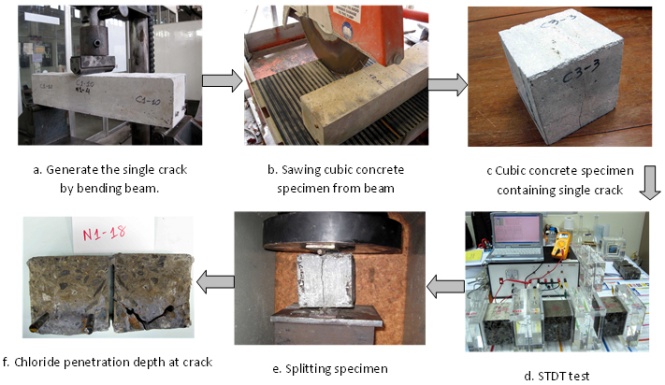 | Figure 5. The schematically experimental procedure |
3.1. The Correlation between Crack Depth and Crack Width
From the experiment results illustrated in Figure 6, it is not difficult to recognize the trends of influence of respective crack depth on the residual crack with the varying W/C ratios are similar. In fact almost all the materials of the beams are similar except for the W/C ratio which causes the differences in compressive strength. However, its influence on the opening crack width is not significant; the steel bars used in the experiment are smooth reinforcing steel, so their stiffness is more important. Another reason is that the crack widths and depths were investigated under linear elastic condition and measured as the applied load retired.  | Figure 6. The correlation between respective crack depth and residual crack width |
It seems that when the crack width increases to a critical value, it will be constant. That is when the value of crack width reaches the yield strength of the reinforced concrete beam.
3.2. Influence of Crack Depth on the Chloride Penetration Depth
Cracks affect strongly the chloride concentration depth. Generally, the chloride ions penetrate through the cracked path into concrete causing the depth of chloride concentration to increase, Figure 7. The experiment results showed the effects of respective crack depth on the chloride penetration depth as in Figure 8.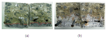 | Figure 7. The difference between chloride concentration depth at uncracked (a) and cracked concrete (b), (W/C =0.5) |
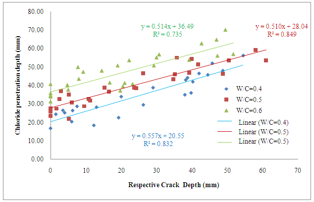 | Figure 8. The chloride penetration depth at crack concrete versus the respective crack depth |
In Figure 8, the chloride penetration depth increased linear with the respective crack depth and the magnitude of that studied is from zero to 60 mm. The results also showed that the depth of chloride penetration when W/C was 0.6 was higher than when W/C was 0.5 and 0.4 at the same depth of crack. It is explained by the influence of the concrete density on the chloride penetration depth. Normally, the density of concrete with W/C of 0.6 is less than the concrete with W/C of 0.5 and 0.4. From this figure, it is easy to regconize that the rates of increasing the chloride penetration depth are similar when the W/C varies from 0.4 to 0.6. From these results, the coefficient of ‘a’ of equation (10) was found to equal 0.53, as follows: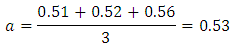 So, the equation (10) which describes the influence of crack depth on the chloride penetration depth at crack location is as follows:
 | (12) |
3.3. The Influence of Crack Depth on the Chloride Diffusion Coefficient at Cracked Concrete
Figure 9 shows the results of the influence of crack depth on the chloride diffusion coefficient by the STDT. Similar to the results of chloride penetration depth, the chloride diffusion coefficient at cracked concrete increases when the crack depth increases. Furthermore, the rates of increasing chloride diffusion coefficient following the increasing crack depth are similar when the ratios of water to cement vary. It can be concluded that the rate of increasing the penetration depth and diffusion coefficient of chloride, when the crack depth varies, is independent of the proportion of concrete (W/C) as concluded by Djerbi [13].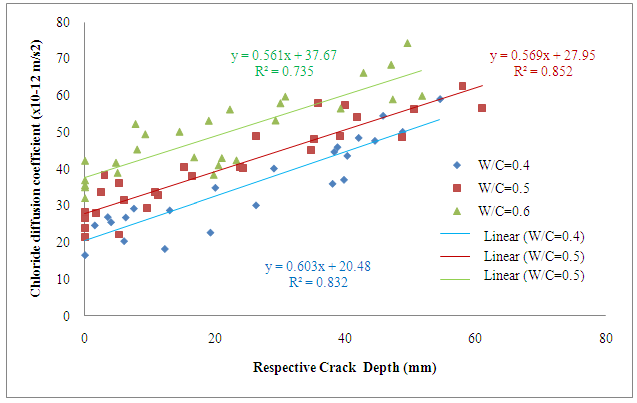 | Figure 9. The influence of crack depth on the chloride diffusion coefficient by STDT |
From the experiment results, the coefficient ‘a1’ of the equation (11) is calculated as follows: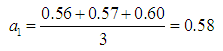 So, the equation (11) describing the influence of crack depth (L) on the ratio of chloride diffusion coefficient between cracked and uncracked concrete would be presented as below:
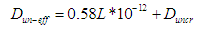 | (13) |
Where: L is respective crack depth (mm).
4. Verification Program
The two back to back of cracked concrete beams were immerged into salt solution of 10% NaCl under static load during several periods. After immersion in salt solution, the chloride profiles were collected at cracked and uncracked location of those beams (Figure 10). Three types of concrete including OPC concrete, FA concrete, SF concrete, were used in the experiment. | Figure 10. Immersion of cracked beam into salt solution and location for collecting the concrete powder |
By applying the Fisk’s 2nd Law (equation 1) and the updated chloride diffusion coefficient at cracked concrete, (equation 4), the chloride profile is calculated. Then, the comparisons between the predicted and experimental results are plotted in Figure 11 to Figure 20. | Figure 11. Comparison between predicted and experimental results (OPC, 2-month immersion) |
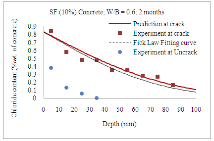 | Figure 12. Comparison between predicted and experimental results (Silicafume Concrete, 2-month immersion) |
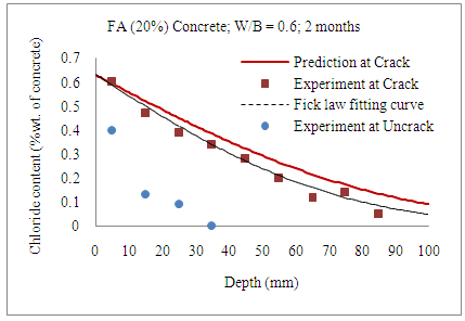 | Figure 13. Comparison between predicted and experimental results (Fly Ash Concrete, 2-month immersion) |
 | Figure 14. Comparison between predicted and experimental results (OPC, 4-month immersion) |
 | Figure 15. Comparison between predicted and experimental results (Silicafume Concrete, 4-month immersion) |
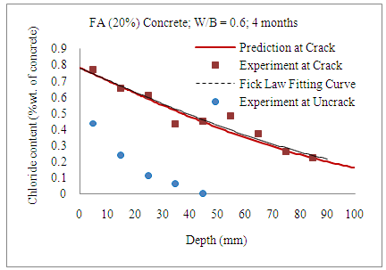 | Figure 16. Comparison between predicted and experimental results (Fly Ash Concrete, 4 -month immersion) |
 | Figure 17. Comparison between predicted and experimental results (Silicafume Concrete, 8-month immersion) |
 | Figure 18. Comparison between predicted and experimental results (Fly Ash Concrete, 8-month immersion) |
 | Figure 19. Comparison between predicted and experimental results (Silicafume Concrete, 12-month immersion) |
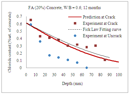 | Figure 20. Comparison between predicted and experimental results (Fly Ash Concrete, 12-month immersion) |
The 1D chloride diffusion model used the surface chloride concentration at the location of crack and the average chloride diffusion coefficient (Dav) to estimate the chloride content at the crack location. The results of 1D chloride diffusion model fitted very well with the experimental results. The experiments also showed that the chloride profiles at cracked locations were higher than at uncracked locations.
5. Conclusions
The characteristics of cracks, such as crack widths and crack lengths (L), were investigated to find out their influences on the chloride penetration into the cracked concrete structure. The results of this research showed that crack lengths had strong influences on the rate of chloride penetration into cracked reinforced concrete structures.The depth of chloride concentration increased with the crack depth and their trends were independent of the proportion of concrete.The research also indicated that the service load had a significant role in increasing the chloride penetration through the varying crack depths. The proposed model provided the simple approach to evaluating the chloride profile of concrete at cracks. This updated model will become an important solution to evaluate the remained service life of concrete structures when the cracks appear.The research also found out the influence of the capillary suction mechanism on the chloride penetration into cracked concrete during the early period of immersion.
ACKNOWLEGMENTS
This research is funded by Vietnam National University HoChiMinh City (VNU-HCM) under grant number C2015-76-01/HĐ-KHCN and has been carried out at Building Materials Laboratory, HoChiMinh City University of Technology, Viet Nam.
References
| [1] | Sugiyama, T., W. Ritthichauy, and Y. Tsuji, Experimental investigation and numerical modeling of chloride penetration and calcium dissolution in saturated concrete. Cement and Concrete Research, 2008. 38(1): p. 49-67. |
| [2] | Sugiyama, T., T.W. Bremner, and Y. Tsuji, Determination of chloride diffusion coefficient and gas permeability of concrete and their relationship. Cement and Concrete Research, 1996. 26(5): p. 781-790. |
| [3] | Bermudez, M.A. and P. Alaejos, Models for Chloride Diffusion Coefficients of Concretes in Tidal Zone. Materials Journal, 2010. 107(1): p. 3-11. |
| [4] | Wang, K., et al., Permeability Study of Crack Concrete. Cement and Concrete Research, 1997. 27(3): p. 12. |
| [5] | Aldea, C.-M., S.P. Shah, and A. Karr, Effect of Cracking on Water and Chloride Permeability of Concrete. Journal of Materials in Civil Engineering, 1999. 11(3): p. 6. |
| [6] | Marsavina, L., et al., Experimental and numerical determination of the chloride penetration in cracked concrete. Construction and Building Materials 2008. 23: p. 10. |
| [7] | Lim, C.C., N. Gowripalan, and V. Sirivivatnanon, Microcracking and chloride permeability of concrete under uniaxial compression. Cement & Concrete Composites, 2000. 22: p. 7. |
| [8] | Mien, T.V., B. Stitmannaithum, and T. Nawa, Chloride penetration into concrete using various cement types under flexural cyclical load and tidal evironment. The IES Journal Part A: Civil & Structural Engineering, 2009. 2(3): p. 13. |
| [9] | Mien, T.V., B. Stitmannaithum, and T. Nawa, Simulation of chloride penetration into concrete structures subjected to both cyclic flexural loads and tidal effects. Computers and Concrete, 2009. 6: p. 15. |
| [10] | Sugiyama, T., Y. Tsuji, and T.W. Bremner, Relationship between coulomb and migration coefficient of chloride ions for concrete in a steady-state chloride migration test. Magazine of Concrete Research, 2001. 53(1): p. 13-24. |
| [11] | Takewaka, K., T. Yamaguchi, and S. Maeda, Simulation Model for Deterioration of Concrete Structures due to Chloride Attack. Journal of Advanced Concrete Technology, 2003. 1: p. 8. |
| [12] | Ismail, M., et al., Effect of crack opening on the local diffusion of chloride in inert materials. Cement and Concrete Research 2004. 34 p. 5. |
| [13] | Djerbi, A., et al., Influence of traversing crack on chloride diffusion into concrete. Cement and Concrete Research, 2008. 38: p. 7. |
| [14] | Ismail, M., et al., Effect of crack opening on the local diffusion of chloride in cracked mortar samples. Cement and Concrete Research, 2008. 38(8-9): p. 1106-1111. |
 Abstract
 Reference
 Full-Text PDF
 Full-text HTML