-
Paper Information
- Paper Submission
-
Journal Information
- About This Journal
- Editorial Board
- Current Issue
- Archive
- Author Guidelines
- Contact Us
Journal of Civil Engineering Research
p-ISSN: 2163-2316 e-ISSN: 2163-2340
2015; 5(3): 59-66
doi:10.5923/j.jce.20150503.02
Structural Response to Differential Settlement of Its Foundations
 Abstract
 Reference
 Full-Text PDF
 Full-text HTML
Lan Lin, Adel Hanna, Anup Sinha, Lucia Tirca
Department of Building, Civil and Environmental Engineering, Concordia University, Montreal, Canada
Correspondence to: Lan Lin, Department of Building, Civil and Environmental Engineering, Concordia University, Montreal, Canada.
| Email: |  |
Copyright © 2015 Scientific & Academic Publishing. All Rights Reserved.
Foundation design necessitates two different studies: one deals with the bearing capacity of the soil; the other is concerned with the foundation settlements. Considering that the loads transferred from the superstructure to the foundation are non-uniform, differential settlements between the foundation's elements are expected, which will generate additional forces in the members of the superstructure. In most of the foundation engineering manuals, allowable differential settlement between the foundation elements should not exceed 25mm. In this study, a three-dimensional nonlinear finite element model was developed for a 10-storey regular building. The dead and live loads were applied as uniform load over the entire floor/roof area. The responses of the structure to the prescribed settlement of the corner, edge and center columns were presented in terms of axial forces and vertical displacements of columns in each floor, bending moments and shear forces in beams. The results of this study will lead foundation designers to limit differential settlement for columns. Furthermore, it may lead to more communications between the structure and the foundation designers to trade-off between the allowable differential settlement and the induced stresses in the structure, in order to achieve the most economical design without compromising on the safety.
Keywords: Foundations, Differentialsettlement, 3-Dfinite element modeling, Nonlinear pushover analysis, Elastic analysis, Structural response, Demand capacity, Building codes
Cite this paper: Lan Lin, Adel Hanna, Anup Sinha, Lucia Tirca, Structural Response to Differential Settlement of Its Foundations, Journal of Civil Engineering Research, Vol. 5 No. 3, 2015, pp. 59-66. doi: 10.5923/j.jce.20150503.02.
Article Outline
1. Introduction
- Buildings are made of two main components: the superstructure, which is the part of the building above ground, and the substructure or the foundation, which is the part of the building located underground. The superstructures are designed by structure engineers with a mandate to design the structural elements to support the loads acting on the building utilizing a reasonable factor of safety. The substructures or the foundations are designed by geotechnical engineers with a mandate to examine the soil condition in the proposed site and to select the appropriate foundation type, which is capable to transfer the building load to the overlying soil. The design of each component follows some design theories, codes and common practice made especially for that component. Communication between these two groups of designers is poor and often does not exist, which may lead to uneconomical design or catastrophic failure of the structure. While values of the settlements of the foundation's elements can be predicted during the design stage, stresses induced in the structure's elements because of this settlement remains unknown. Furthermore, excessive and/or uncalculated settlements may occur during the lifespan of the structure due to environmental changes, such as flooding or rising the groundwater table or construction in the neighbourhood [1] [2] [3], or new excavation [4] [5], and accordingly, additional stresses will be induced in the structure's elements. Therefore, it is important for the foundation and the structure designers to exchange the data available during the design stage in order to avoid unforeseen damages and perhaps catastrophic failure of the building [6] [7]. In the literature, values for the allowable differential settlements were recommended for certain types of structures [8] [9] [10]. Hanna et al. [11] and Hanna [12] reported on the effect of differential settlement on a high-rise concrete building and emphasized the need for communication among designers to achieve economical and safe design.It should be made clear that the higher the allowable differential settlement between the foundation's elements, the lower the foundation cost and the higher the additional stresses induced in the superstructure, and accordingly, the higher the cost of the superstructure and vice versa. Given this, a trade-off between the costs of the superstructure and its foundation should be performed during the design stage in order to achieve the most economical design for the building, without comprising on the safety. This can only be achieved if a line of communication is opened between the designers of both components based on knowledge.The current practice for the design of buildings, as stipulated in the National Building Code of Canada (NBCC) [13] and other international design manuals, e.g. IBC [14], does not account for the stresses induced in the structure's elements due to the differential settlement of the foundations. It is necessary to mention that ACI [15] purposed an allowable differential settlement of 0.75 inch for classic structures, which believed to be tolerated by the factor of safety.
2. Building Description
- A 10-storey reinforced concrete frame building located in the City of Ottawa, Ontario, Canada was considered in this study. The geometrical configuration of the building is given in Fig. 1. The building is 24 x 24 m, and has a floor height of 4.0 m. The spans in both directions are 6.0 m. The floor system consists of a two-way slab supported by conventional beams. The lateral load resisting system of the building consists of reinforced concrete moment resisting frames (RC-MRF) in both directions.The structure was designed by Cimillia-Erkman [16] as an office building in accordance with the 2005 edition of NBCC [17] as moderately ductile RC-MRF building for seismic loads, and was modified for the purpose of this study according to the provisions of the latest 2010 edition of NBCC [13]. The structure was designed for 1.5 kPa dead load on the floors, and 1.0 kPa on the roof. It is important to note that these loads do not include the self-weight of the structural members. Live loads of 2.4 kPa were applied on the floors, and 1.0 kPa on the roof. The foundation was assumed to be on stiff soil represented by site class C (i.e., shear wave velocity between 360 m/s and 750 m/s) according to NBCC. Furthermore, the following values were used in the design: compressive strength of concrete fc' = 30 MPa, and yield strength of reinforcement fy = 400 MPa.
3. Numerical Model
- A three-dimensional nonlinear finite element model was developed for the building under consideration using the program SAP2000 [18]. Beams and columns were modelled as 'beam' elements, and slabs as 'shell' elements. In total, the model consisted of 2650 beam elements, 5760 shell elements, and 6275 joints. The connections between beams and columns were assumed to be rigid, and the columns were assumed to be fully fixed with its foundation. The length of the rigid joint was taken as half depth of the beam or column depending on the location of the joint, and the axial deformations were only considered for columns. The dead and live loads were applied as uniform load over the entire floor/roof area. The cross-sectional area, moment of inertia, and torsional constant were determined based on the geometrical properties given for each element. In order to take into account the effect of concrete cracking, the moment of inertia of the beams and columns were reduced to 0.35Ig and 0.70Ig, respectively, according to the CSA A23.3 [19], where Ig is the moment of inertia of the gross section.Inelastic deformation was assumed at the ends of the beams and columns, where plastic hinges can be formed, in order to consider the nonlinearity of the elements due to the settlement. Each plastic hinge is modeled as a discrete point hinge having its length as 5% of the span length for hinges on beams, and 5% of the floor height for hinges on columns [20]. The nonlinear behavior of hinges was represented by a force-deformation (i.e., moment-rotation) curve following FEMA 356 [21] and ASCE/SEI 7-05 [22].
4. Results
- In this study, three cases of the foundation settlement were considered: a prescribed 25 mm settlement was assigned to the foundation under the corner, edge, and center column, known as A1, C1, and C3, respectively (see Fig. 1). Preliminary analysis was performed on column C3 using nonlinear pushover analysis method. The results showed that the building behaved elastically at the settlement of 25 mm. Therefore, linear static analysis was conducted in this study. Structural responses in terms of vertical displacement of column, axial force in column, bending moment and shear force in beam were determined.
 | Figure 1. Geometrical configuration of the building |
4.1. Column Displacement
- Figure 2 presents the column displacement versus floor level due to 25 mm settlement assigned to the center column C3. It can be seen in the figure that the vertical displacement of column C3 is larger than that of the interior columns B3 and D3; while no displacement is generated on the edge columns A3 and E3. Analyses were also conducted on columns A1 and C1, where similar observation was noted. Figure 3 illustrates the results of three cases given above. It can be noted that the corner column at joint A1 experiences the largest displacement, and accordingly, it represents the most critical case for the structure. Furthermore, it was noticed that the displacement of the column decreases with the increasing of the floor level.
 | Figure 2. Vertical displacements of columns due to the settling of column C3 |
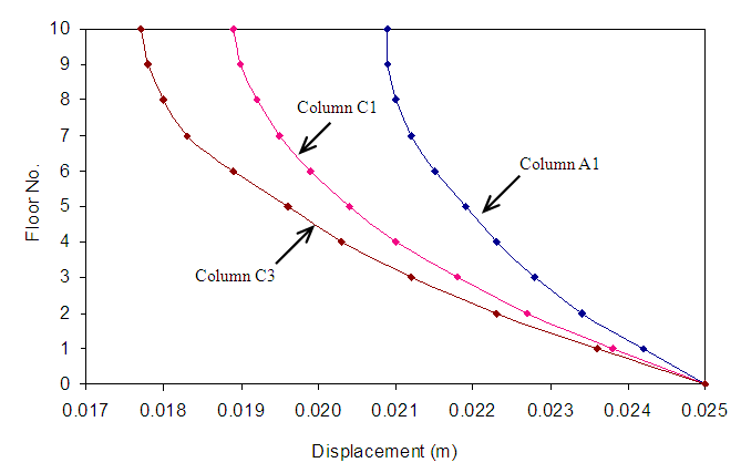 | Figure 3. Vertical displacements generated in the settling columns of the three cases |
4.2. Axial Force Developed in Columns
- Figure 4 presents the axial force developed in columns of frame 3 due to the settlement of the center column C3. The positive and negative values on the figure present the tensile and compressive force, respectively. The results in Fig. 4 show that the settlement develops tensile force in the settling column C3, while it generates compressive force in all surrounding columns B3 and D3, and it does not affect columns A3 and E3. Furthermore, the axial force decreases with the increase of the floor level in a nonlinear fashion. Similar conclusion was drawn for the case of settling of the edge and corner columns. Figure 5 shows the axial forces developed in the three settling columns considered in this investigation. It can be seen that the largest axial force is induced in the center column, with lesser extend in the edge column followed by the corner column.
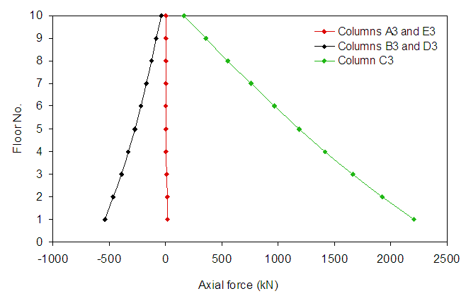 | Figure 4. Axial forces developed in columns due to the settling of column C3 |
 | Figure 5. Axial forces generated in the settling columns of the three cases considered |
4.3. Bending Moments Developed in Beams
- Figure 6 shows the maximum positive bending moments developed in the adjacent beams corresponding to the settling of the column for the three cases considered in the study. It should be noted that negative moments were also induced by the settlement. More specifically, for the case of settling of the edge and center columns, the positive moment was larger than the negative moment by about 15% to 20% respectively, while for the case of the corner column, they are quite close. Table 1 presents the ratios of the moment due to the foundation settlement to that due to the dead load applied on the building. It can be noted that the moment generated by the foundation settlement was significantly larger than that by dead load. This should alert both structure and foundation designers on the seriousness of the role of foundation differential settlement on the safety and the serviceability of buildings. Furthermore, it may invite designers to integrate these two components in one by allowing trade-off between the two parts to achieve economical design without compromising on safety.
 | Figure 6. Maximum bending moments developed in beams adjacent to the settling columns of the three cases |
|

4.4. Shear Forces Developed in Beams
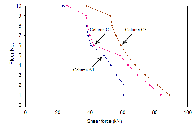
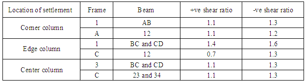
- Figure 7 presents the maximum positive shear forces developed in beams due to the settlement of the column. It can be seen that the settlement of the center column creates the largest shear forces. Furthermore, the shear forces due to the settlement assigned to the corner and edge columns were almost identical for the beams above the 6th floor. Table 2 presents a summary of the ratios of the shear force due to settlement to that due to dead load for the three cases examined in this investigation. It can be noted that the produced ratio for the shear was relatively less than those for bending, which implies that the foundation settlement may cause damage due to moments as compared to shear.
 | Figure 7. Maximum shear forces developed in beams adjacent to the settling columns of the three cases |
|
4.5. Affected Areas Caused by the Settlement
- Based on the results of this study, it can be reported herein that the most affected area in the building due to the differential settlement of its foundation is within one span from the settling column as illustrated in Fig. 8. Beyond these areas, the settlement does not have any effect on the structural members. The induced stresses including axial forces, bending moments, and shears decrease gradually with the increase of the floor level.
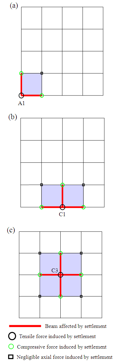 | Figure 8. Affected area due to the settling of: (a) corner column A1; (b) edge column C1; (c) center column C3 |
4.6. Demand/Capacity Ratio (DCR)
- In this investigation the Demand/Capacity Ratio (DCR) of the members affected by the foundation settlement was calculated using the following equation,
 | (1) |
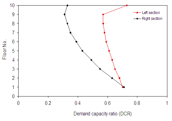 | Figure 9. Demand capacity ratios of beams BC and CD of frame 3 due to the settling of the center column C3 |
5. Conclusions
- The response of a building structure due to the differential settlement of its foundation was evaluated. In this investigation, the corner, edge and center columns of a 10-storey reinforced concrete moment resisting frame building were subjected to a differential settlement of 25 mm, which is the maximum allowable settlement given in the current design codes. Nonlinear pushover analysis was conducted on a 3-D model of the building using the program SAP2000. The vertical displacement of the column, axial force developed in columns, shear forces and bending moments developed in beams were determined from the analysis. In addition, the demand capacity ratio of the structural members was computed in order to assess the current condition and the potential failure of the member. The affected area in the structure due to differential settlement of a given column was determined. The following was concluded, 1. The structure behaves elastically for the settlement up to about 25 mm, beyond which, inelastic deformations are developed.2. The settlement of the center column represents the most critical case for the structure in terms of the forces, while the corner column represent the least.3. The vertical displacement of the column subjected to settlement reaches its maximum value at the foundation level and decreases with the increasing of the floor level. However, for the other columns within one span from the settling column, the vertical displacement increases with the increase of the floor number. The settlement of the corner column produces the maximum displacement, and accordingly, it represents the most critical case for the vertical displacement of the structure.4. Tensile force is generated in the settling column, while compressive force is developed in the adjacent columns within one span from that column.5. Significant bending moments are developed in adjacent beams of the settling column, while settlement induces relatively smaller shear forces in them. It indicates foundation settlement has more effects on bending moment than shear.6. The demand capacity ratio for moment is significantly larger than that for the axial force and shear. In addition, settlement may cause failure of the beams at lower floors as well as on the top floors due to the higher DCR on these floors.7. The affected beams and columns of the settling column are located within one span from that column, beyond which the response is gradually reduced.8. A higher factor of safety for the design of the structure elements should be restructured according to the deduced DCR in order to minimize the effect of the deferential settlement.9. Center columns should be designed for a relatively smaller allowable settlement in order to avoid excessive stresses in the structure and perhaps catastrophic failure.10. The induced stresses presented in this paper are only for a differential settlement of 25mm, which is within or at the allowable load level. If, however, the differential settlement is excessive, whether it was known at the design stage or was unpredictable, the induced stresses will be much higher and the structure may reach the failure point.11. A trade-off between the factor of safety of the structure and the allowable differential settlement of the foundations should be performed at the design stage in order to achieve the most economical design without compromising on the safety and serviceability of the building.
ACKNOWLEDGEMENTS
- The financial support provided by the Natural Sciences and Engineering Research Council of Canada is gratefully acknowledged by the authors. In addition, the reviewers' comments are highly appreciated.