Fariborz M. Tehrani, Rosa M. Serrano
Department of Civil and Geomatics Engineering, California State University, Fresno, USA
Correspondence to: Fariborz M. Tehrani, Department of Civil and Geomatics Engineering, California State University, Fresno, USA.
| Email: |  |
Copyright © 2014 Scientific & Academic Publishing. All Rights Reserved.
Abstract
Wheel abnormality intensifies impact characteristics of train loads on railway concrete ties. Concrete ties are commonly prestressed with single or multiple tendons. This paper presents experimental studies on crack propagation of prestressed concrete ties with single steel tendons subjected to impact loads. The presented study includes the effect of supplementary fiber reinforcement using polypropylene fibers on crack arrest, in terms of fiber type and content by volume. Concrete ties are modeled as flexural beams subject to four-point loading system. A mass dropped from predetermined height simulated the wheel impact loads. Experimental results include crack patterns, dimensions, and accompanied loads. The concrete beams reinforced with fibers experienced a delay in crack growth in both length and width. Further, the fiber reinforced beams had smaller initial crack length in comparison to beams with no fiber reinforcement.
Keywords:
Prestressed concrete, Railroad ties, Impact forces, Cracking, Crack propagation, Wheel abnormality, Fiber reinforced concrete, Polypropylene fiber
Cite this paper: Fariborz M. Tehrani, Rosa M. Serrano, Crack Propagation of Concrete Beams Prestressed with Single Strand Tendons, Journal of Civil Engineering Research, Vol. 4 No. 3, 2014, pp. 71-81. doi: 10.5923/j.jce.20140403.03.
1. Introduction
The substructure and superstructure are the two main components of train tracks. The substructure includes the ballast, subgrade, and ground formation, while the superstructure includes rails, rail pads, fastening system, and railway ties, which are also known as sleepers (Figure 1). The rails guide the train vehicle and transfer the train loads to ties. Ties are major structural components of railway structures, as they connect the steel rail to the subgrade. Efficient design of ties can contribute to better long-term performance, longer life span, and lower maintenance costs. Concrete materials have potentials to gradually replace conventional wood ties due to higher demands in railway industry in terms of strength and durability. However, cracking is a concern for concrete ties as it would adversely impact the durability of the concrete. Prestressing is a common technique to provide an efficient design for concrete ties. Concrete railway ties are typically prestressed with 7-strand or single-strand steel tendons to increase their load capacity and reduce the tensile zone within the cross section of the tie. There are two types of concrete ties: mono-block ties and twin-block ties [14]. This research will focus on the mono-block concrete ties. 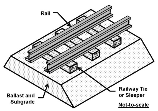 | Figure 1. Schematic model of railway structures (after Kaewunruen and Remennikov, 2009) |
2. Research Significance
This research aims to experimentally study the crack initiation and propagation of alternative concrete ties prestressed with single-strand tendons. Further, this study investigates the effect of fiber reinforcement on cracking and draws performance comparisons from the results. Concrete ties will be modeled as rectangular beams. An impact attenuator will deliver the loads simulating high impact loads caused by wheel abnormalities. Analytical studies include a moment-curvature analysis and a load-deflection analysis, which are required for developing experimental methodology. This research advances the state of research on implementation of fiber reinforcement in prestressed concrete ties. The results have potential to impact state of practice in precast concrete industry by introducing new reinforcement methods.
3. Background
Railway ties are crucial components of railway structures because they transfer the load from the wheels to the substructure. Concrete ties in particular have been of high interest in research and practice due to their strength advantages over traditional wood ties. However, extreme loading conditions make concrete ties susceptible to cracking and failure, thus requiring frequent maintenance and replacement. Prestressing concrete with steel tendons is a conventional method to overcome the cracking problem of the concrete and increase the strength of the tie. Fiber reinforcement is a supplementary reinforcement method that also contributes to crack control.
3.1. Railroad Concrete Ties
Wood materials used to be the popular choices for ties due to their wide availability. In the early 1970’s, the railroad industry began using concrete railroad ties with the involvement of the Portland Cement Association [12]. Concrete ties began appearing on railroad track more than wood ties because of their performance and economic advantages. In terms of durability and capacity, concrete ties out last wood ties. Today, concrete ties can be seen in both heavy haul rail and transit lines. Concrete ties are manufactured with high strength concrete, generally with minimum specified compressive strength of 7,000 psi. Number and configuration of strands and tendons vary in practice and may include single strand, 7-strand, etc. The size of the prestressing tendons used to be between 4.8 mm (0.19 in) to 5.3 mm (0.21 in), but, it has increased over time. Today, most manufacturers use tendons with a diameter of 9.5 mm (0.375 in). Steel tendons in concrete ties are also made of high strength steel. The typical ultimate strength is 1.86 GPa (270 ksi) for 7-strand tendons and 1.79 GPa (260 ksi) for single strand tendons. The use of 7-strand tendons or single-strand tendons is fully decided by manufacturers. One of the most prominent issues with concrete tie production is the bonding between the prestressing steel tendons and the concrete. This issue has been minimized by using larger number of tendons with smaller diameters [18].
3.2. Failure Mechanism
Flexural cracking is a common type of failure in concrete ties. This type of cracking is also known as center binding because the cracking occurs at the center of the concrete tie rather than the application point of the load at the rail seats. Failure of ballast support underneath the tie facilitates the flexural cracking. Such failure allows the concrete tie to deform vertically in response to cycling load transferred from the train. This deformation in turn contributes to additional deterioration of the ballast. Ultimately, the concrete tie resting on crushed ballast will be subject to large negative moments at the center of the span and will crack consequently. To prevent this type of failure, the ballast underneath the concrete tie should be replaced often during maintenance efforts. Other types of failures are also possible due to failure of track structure components, e.g., the rail fastener, or other components, e.g., the rail seat abrasion [7]. These types of failure do not affect the design of concrete ties, and therefore will be outside of the scope of this paper.
3.3. Impact Loading
Current railroad ties are designed to develop no cracks under normal loading; however, there are instances where extreme loading conditions take place. Extreme loading conditions exist when wheel abnormalities are present in the train. Examples of wheel abnormalities include wheel flats, out of round wheels, wheel corrugation, or dipped welds. Figure 2 shows an example of wheel abnormalities [23]. Such wheel abnormalities may cause high dynamic forces on the rail. The rail transfers the load to the concrete ties; therefore, the concrete ties are also affected by these extreme loading conditions. The typical rail seat design load is 100 kN (22.5 kip); however, studies conducted by Kaewunruen and Remennikov (2010) indicate that extreme loading conditions induce loads within 200 to 700 kN (45 to 135 kip) range [15]. The extreme impact forces can be modeled as a shock pulse [24]. These infrequent but high magnitude loads produced by wheel abnormalities cause cracking in the concrete ties [19].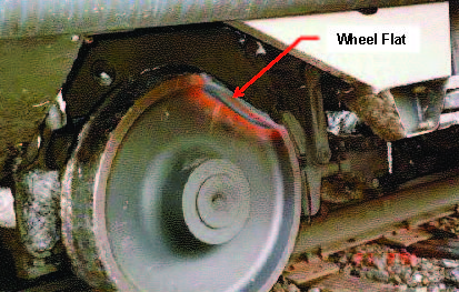 | Figure 2. Wheel abnormality: wheel flat (after Transportation Safety Board of Canada, 1996) |
3.4. Impact Attenuator
Kaewunruen and Remennikov (2011) developed a testing set-up to investigate the crack propagation due to impact loads caused by a dropping mass with maximum drop velocity of 10 m/s (33 ft/s). The testing rig was used to study various behaviors of prestressed concrete ties. Their experimental investigation focused on calculations of energy loss and absorption of the testing rig at various heights. From this research project it was concluded that the energy balance theory can be applied to prestressed concrete ties. Using this information, energy efficiencies of other testing rigs may be determined [16].
3.5. Fiber Reinforcement
Numerous studies have been done on the advantages of fiber reinforcement in concrete [2]. One particular early example is the work conducted by Ashour and Wafa (1993). They used fiber with various contents to observe the crack propagation and ductility of the beams. Beam specimens were simply supported, subject to four-point static load and reinforced with grade 60 tendons. Observations revealed that fiber reinforcement reduced the width of flexural cracks. The authors also determined that increasing the fiber content resulted to an increase in deflection and energy absorbed at failure, which will cause larger toughness [5]. In a later work, Daniel and Loukili (2002) focused on the performance of high strength concrete beams with fiber reinforcement under static as well as cyclic loading. That study incorporated fibers with various length and content. Authors noted the positive effect of fibers on controlling random cracks as well as more ductile load-deflection curve [8]. Kakooei et al. (2012) studied the effects of polypropylene fibers on reinforced concrete. The researchers determined that fibers can increase the durability of the concrete by reducing cracking and permeability [17]. Thus, it is evident from past studies that the addition of fiber has a positive impact on the behavior and lifespan of concrete beams.
4. Methodology
The experimental work in this research includes testing of prestressed concrete beams subject to impact loading. Supplementary static tests are also performed to measure properties of concrete and provide a base for comparing static and dynamic results. The analytical work included moment-curvature analysis on the cross-section of beams to predict results and proportion geometric and reinforcement parameters. The impact testing system was configured using dynamic analysis of the ties subjected to loading caused by the wheel abnormalities.
4.1. Specimen Preparation
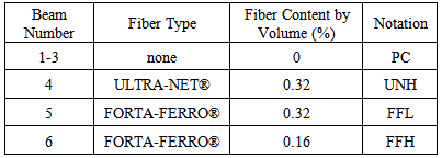
All specimens were cast in Mid State Precast LP plant using the high strength concrete mix. Four small beams, 0.10 m (4 in) square by 1.2 m (48 in) length, were cast to obtain flexural capacity of concrete subject to static loads. These tests supplemented standard compressive tests on concrete cylinders, 0.1 m (4 in) diameter by 0.2 m (8 in) height, to obtain specified compressive strength of concrete for each mix design per ASTM C31 [4]. Total of six prestressed beams, 1.2-m (48-in) long, were prepared for dynamic testing, including three fiber-reinforced concrete beams. Fibers used in preparing the specimens were manufactured by FORTA Corporation, including FORTA-FERRO® and ULTRA-NET®. Both fibers are manufactured from 100% virgin polypropylene material. In addition, these types of fibers are both non-corrosive, non-magnetic and 100% alkali proof. The FORTA-FERRO® fiber is a patented macro-fiber blend of a twisted non-fibrillating monofilament fiber and a fibrillating network fiber. The purpose of this type of fiber is to improve the impact strength and fatigue resistance of concrete. The typical length of these fibers is 57 mm (2.25 in), and the recommended dosage rate is 0.2% to 2.0% by volume [11]. The ULTRA-NET® fibers have a fibrillated system and an average length of 38 mm (1.5 in). The recommended dosage rate is 0.1% for this fiber, and it is recommended by the manufacturer to reduce settlement cracking [10]. In this study, two different dosages of 0.32% and 0.16% were used out of consideration for workability of fresh concrete. Table 1 summarizes the fiber reinforcement in each beam. Further, Figure 3 shows the mix process for each fiber using electric mixer. 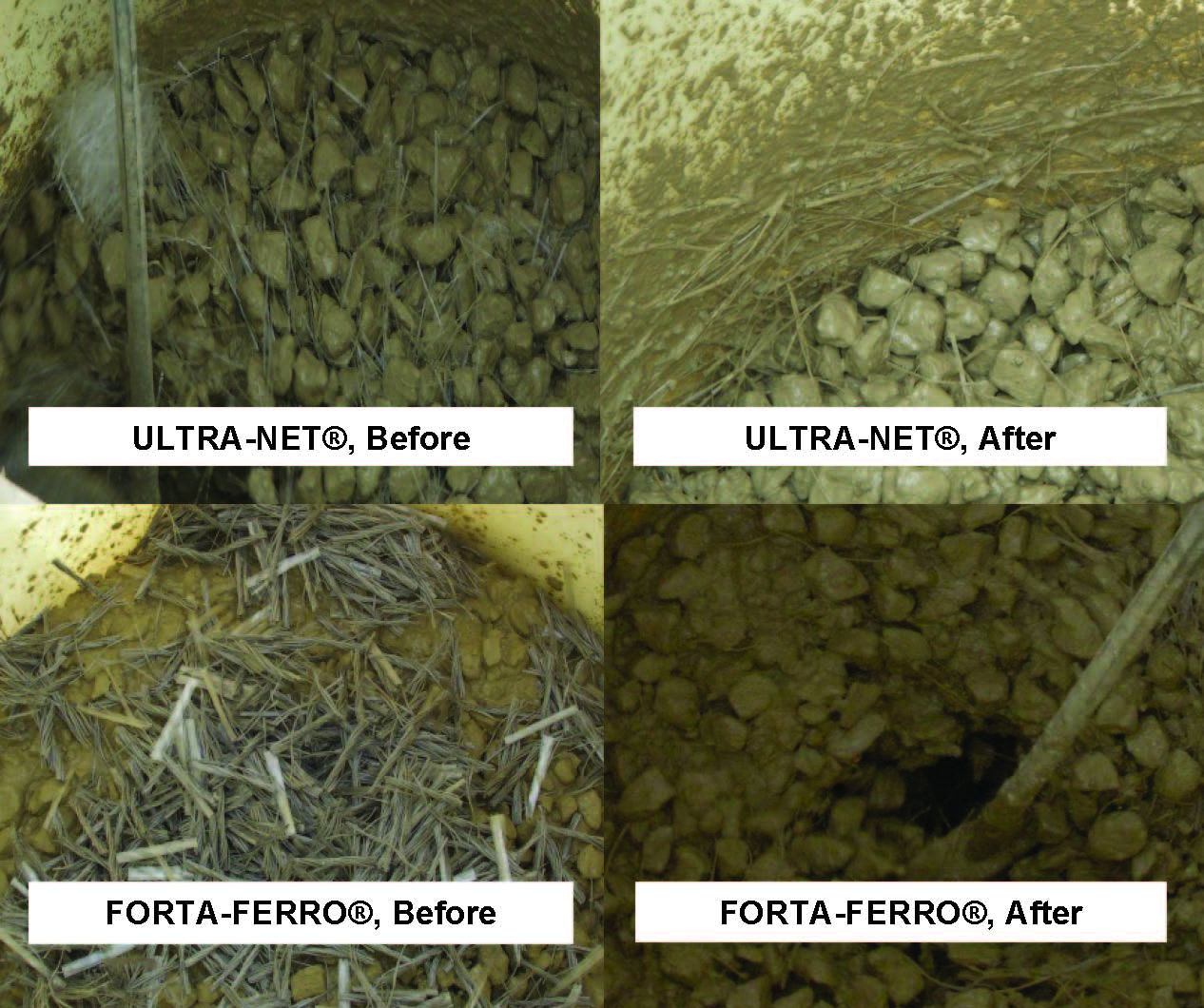 | Figure 3. Before (left) and after (right) mixing of ULTRA-NET® (top) and FORTA_FERRO® (bottom) fibers |
Table 1. Fiber reinforcement in prestressed beam specimens
 |
| |
|
Each beam had a single tendon located at 38 mm (1.5 in) from the bottom. Tendons were of 9.5 mm (0.375 in) diameter. The prestressing force delivered from the hydraulic ram applied 113.8 MPa (16,500 psi) on tendons. Considering the prestress losses, the prestressing applied to the beams and used in analytical calculations was 110.3 MPa (16,000 psi). Typically, concrete ties have a trapezoidal cross section. However, the specimens were cast in rectangular molds with final dimensions of 0.15 m (6 in) width and 0.10 m (4 in) height. The reinforcement ratio was adjusted properly based on these dimensions. Using the minimum dimensions allowed by the American Railway and Maintenance Association (AREMA), the area of a concrete tie cross section is estimated to be 0.025 m2 (39 in2). This area is taken as the width of the beam times the distance from the top fiber to the pre-stressing tendon. AREMA accounts for a cover of 9.5 mm (0.375 in), or 0.75 times the diameter of the steel tendon [3].
4.2. Section Analysis
The moment-curvature relationship is developed based on the non-linear behavior of the section. The concrete model follows a simple parabolic stress-strain (σ-ε) curve in compression and a linear relation in tension (Figure 4). The compression equation is written as follows: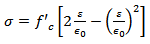 | (1) |
whereσ = stressε = strainf’c = the specified compressive strength of concreteε0 = strain at peak compressive strength, assumed to be 0.002 The tensile strength, fr, is essential in predicting cracking strength, even though it does not substantially contribute to the ultimate strength of the section. This modulus is defined per ACI 318 recommendations: | (2) |
where  is defined in psi (6.89 KPa). The ultimate compressive strain is 0.003 following ACI 318 [1]. The steel is modeled as an elasto-plastic material with modulus of elasticity of 29,000 ksi (200 GPa), and yield stress of 270 ksi (1.86 MPa).
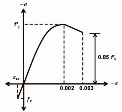 | Figure 4. Stress-strain relationship for concrete |
The moment-curvature relationship can be further simplified to a tri-linear model to facilitate development of the load-deflection curve (Figure 5). The first point along this curve marks the tensile cracking in concrete, when the tensile stress reaches the rupture modulus as specified in ACI 318. The next two points mark steel yielding and compressive failure of concrete, respectively. The load-displacement relationship is developed based on the moment-curvature analysis of the section and plastic analysis of the simply-supported prestressed beam subjected to concentrated load at the mid-span. For instance, the minimum cracking strength of a simply supported beam on 38 in span is calculated to be 4.2 kN (0.94 kip).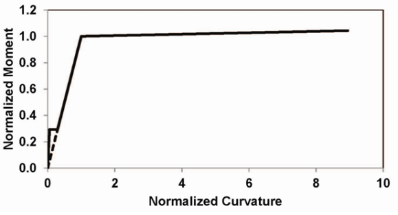 | Figure 5. Idealized moment-curvature relationship of the prestressed beam |
4.3. Beam Analysis
In an ideal situation, train wheels are perfectly round. As wheels approach a concrete tie, load is transferred to the concrete ties through the rail. The total load on a single concrete tie is the sum of each of the loads applied by all the wheels in a train car. The wheels can cause loading or unloading, as they approach or depart the specific tie. Figure 6 shows resulted support reactions for this problem following the classic solution using the stiffness matrix of a beam [9]. This solution can be extended to continuous beams supported on discrete elastic support (Figure 7) [13]. It is obvious that the maximum transferred load to the tie occurs when a wheel is directly over the concrete tie, regardless of the rigidity of the support. However, the applied load on the tie decreases as the support rigidity degrades [21]. Further, each tie will be subject to combination of cyclic loads as consecutive wheels pass over it with a frequency proportioned to the train speed.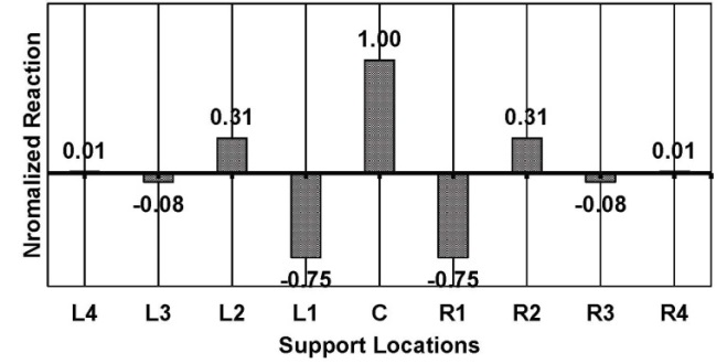 | Figure 6. Reaction of Ties Supporting a Continuous Rail |
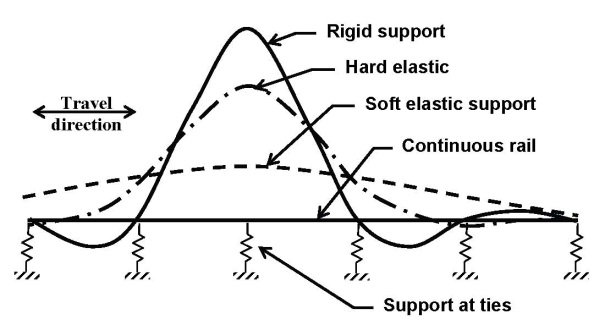 | Figure 7. Qualitative influence lines for moving wheel load on ties [21] |
The impact load on the beam can be modeled as a load applied during a very short time, also known as impulse (Figure 8). For the purpose of this section, a simple and idealistic analysis can be performed by modeling the beam as a single-degree-of-freedom system. It can be shown that the maximum response of the system occurs during the free vibration phase, as long as the load duration is less than half of the natural period of structure, which is the case for train load on concrete tie. This maximum response for an un-damped system is twice static response of the system. Further, it can be noted that the response of the system during the loading phase becomes negligible for very short load durations. However, the change in momentum due to applied impulse will cause a change in initial velocity of the system at the end of the load duration. Thus, the free vibration of the system after the impact will be set based on this velocity. Classic solutions to this problem imply that the load shape does not have a significant effect on the response of the system [6]. 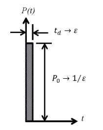 | Figure 8. Modeling the Impulse Load on Concrete Tie |
The dynamic load caused by wheels with abnormalities will follow a similar pattern to the static load as shown in Figure 9. However, the influence lines are not continuous, as the wheel will impact the rail when the location of abnormality on the wheel comes in contact with the rail. Thus, the concrete tie receives the load from an abnormal wheel as an impact. This can be shown as a bar chart instead of a continuous curve, where each bar represents a short duration force. The distance between two consecutive bars is the perimeter of the wheel. The perimeter of the wheel depends on the type of the train car, and may often be greater than tie spacing. For instance, the wheel diameter is 940 mm (37 in) for a passenger car, while the typical spacing for concrete ties is 0.6 m (2ft) [20]. If this train approaches the tie at 129 km/h (80 mph), the impact duration for a wheel with flat abnormality on portion of its perimeter (similar to the one shown in Figure 2) will be in the order of thousandths of a second. At the same time, the gap between these loads is proportional to the distance between consecutive wheels and will be substantially larger [7].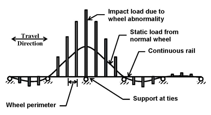 | Figure 9. Wheel loads with and without abnormalities |
4.4. Impact Testing
The impact testing machine is designed and manufactured by a team of mechanical engineering students (Bennet, Muthwill and Van) at Fresno State University. Figure 10 shows a schematic of the impact machine. An electric hoist was added to the original design to facilitate and increase the safety of the experiments in this research. The base of the impact machine has a diameter of 0.6 m (2 ft). The height of the machine is 3.6 m (12 ft). A frame is built at the base of the machine to provide simple supports for the beam specimen. The load is transferred from the massive plate to the specimen using a guided rod. Safety ropes hold the various parts together without applying any force on the system.  | Figure 10. Impact testing machine |
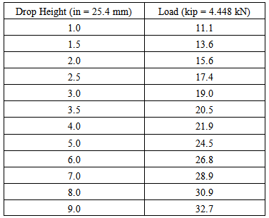
The weight of the mass delivering the impact in the experimental methodology is set to 1.56 kN (350 lb). Then, the dropping height is correlated with the maximum deflection of the system upon impact [22]. This relationship facilitates calculation of the drop height based on required deflection to cause cracking or failure in the beam specimens. The deflection due to static loads is analytically calculated using section analysis, and experimentally verified in the lab. To observe the crack propagation at various loads, each beam was subjected to multiple impacts with increasing drop heights as shown in Figure 11. Using the above energy equation, the impact load associated with each drop height can be obtained (Table 2).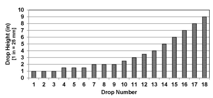 | Figure 11. Order of drop heights for consecutive impact tests |
Table 2. Impact Loads associated with drop heights in the impact test
 |
| |
|
5. Results
5.1. Compression
Three samples were taken from each concrete mix. One sample was tested after one day of curing at the Mid State Precast LP plant, as part of quality control efforts. The other two samples were cured with other specimens and tested in Fresno State lab. Figure 12 shows the results of these tests. Various concrete mixes are marked with notations as referenced in Table 1. Comparison of force-displacement relationships indicates that fiber-reinforcement has substantially increased the ultimate displacement of specimens. Application of fibers has also increased the peak compressive strength, even though the change is not significant.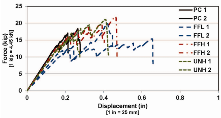 | Figure 12. The effect of fiber reinforcement on compressive force-displacement relationship of concrete cylinders |
5.2. Flexure
Flexural test was performed on simply supported beam specimens with various mix design. Each beam had a 0.10 m by 0.10 m (4 in by 4 in) cross section and tested on 0.76 m (30 in) span. Figure 13 shows the resulted force-displacement relationships. All fiber-reinforced concrete beams showed sustained substantially greater ultimate displacements in comparison to plain concrete beams. Further, the strength and stiffness values are also increased with addition of fibers. It is also apparent that the volume content of fiber had a positive impact on peak strength and ultimate displacement. 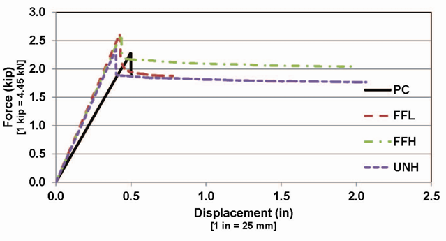 | Figure 13. The effect of fiber reinforcement on flexural force-displacement relationship of concrete beams |
5.3. Static Beam Test
A control prestressed beam plain concrete was tested under static loading on a 5500 Hydraulic Xtend Retrofit System from Instron-STAES Systems. The objective of the test was to determine the load-displacement relationship and verify required load to cause cracking, yielding, or failure in the beam. Further, the observed crack patterns were compared with dynamic testing results. The beam was simply supported over 0.96 m (38 in) span. All beams, including the control beam, were surfaced with a flat latex paint to facilitate the visual observations during crack propagation. Cracks are monitored and marked as loading was in progress. The static load was steadily increased until the beam failed. Figure 14 shows the resulted force-displacement relationship along with stiffness ratios for gross, cracked, and yielded sections.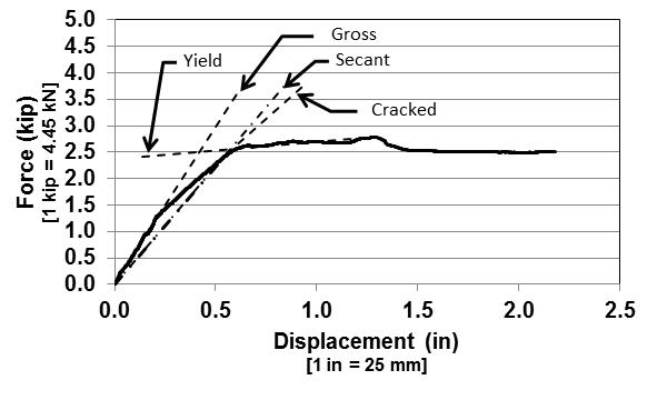 | Figure 14. Force-displacement relationship from static loading |
The first noticeable crack was a flexural crack developed at 5.78 kN (1.3 kip) in the center of the beam. This is larger than the predicted strength based on section analysis, 4.15 kN (934 lb), which was calculated using the conservative equation per ACI 318. The first crack was extended up to 38 mm (1.5 in) from the bottom of the beam, which was the location of the prestressing tendon. Additional cracks developed at higher loads. Figure 15 and Figure 16 show crack development and beam failure, respectively. These figures reveal how secondary shear cracks were also developed during loading. However, it can be observed that flexural cracking was the main cause of ultimate failure. At the same time, the concrete was crushed due to compression at the top fiber of the beam as shown in Figure 17.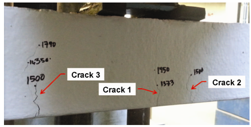 | Figure 15. Crack development due to static load |
 | Figure 16. Beam failure due to static load |
 | Figure 17. Concrete crushing due to static load |
5.4. Impact Beam Tests
The dynamic testing involved dropping the massive plate from increasing heights as shown in Figure 11. The experimental set up for the beam is shown in Figure 18. Geometry and content of specimens were defined in the methodology under specimen preparation. The load associated with each drop height is measured using energy equations, expressed in loading analysis section.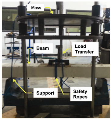 | Figure 18. Experimental set up for impact testing of beams |
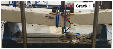
Two prestressed beams with plain concrete (mix design PC in Table 1), similar to the specimen subjected to static load, were tested. To perform a complete comparison with the beam subject to static loading, the initial drop height was set to zero. Then, the height was increased gradually to 12.6 mm (0.5 in) at 1.8 mm (0.07 in) increments. Then, the increment was resumed to be 12.5 mm (0.5 in) as scheduled. Regardless, the first crack appeared below one of the point loads, when the mass was dropped from a height of 38 mm (1.5 in). This was a hair crack extending 75 mm (3 in) in length, as shown in Figure 19. The crack angle in this figure is 90-degree at the bottom fiber, and changes to 45-degree as it extends upward. The width of this crack continued to increase gradually up to 2.84 mm (0.112 in) before failure. Further, noticeable compressive crushing was observed at the top of the specimen directly below the point load (Figure 20). At the drop height of 75 mm (3 in), a flexural crack was developed. Propagation of these cracks caused ultimate failure of the beam when the mass was dropped from 102 mm (4 in). Figure 21 shows this failure, as the beam was broken to two pieces.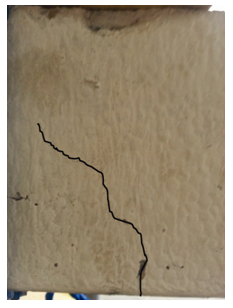 | Figure 19. Crack initiation in prestressed beam, PC1, subject to impact |
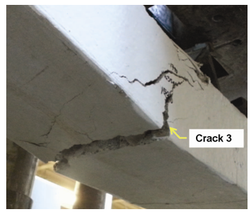
 | Figure 20. Crack propagation in prestressed beam, PC1, subject to impact |
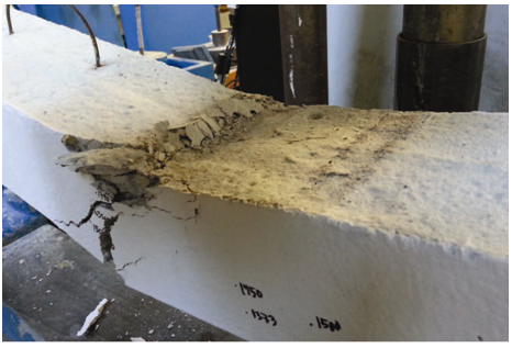
 | Figure 21. Failure of prestressed beam, PC1, subject to impact |
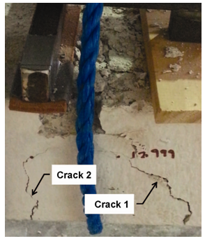
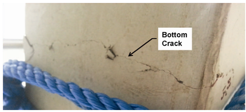
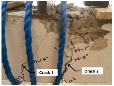
The second prestressed beam with plain concrete exhibited a similar behavior, as it developed the first crack due to dropping mass from 38 mm (1.5 in). The length of crack was measured to be 64 mm (2.5 in) at initiation. Figure 22 shows the crack propagation that resulted in failure of the specimen. This specimen showed slightly larger strength than previous specimen and failed at drop height of 127 mm (5 in). 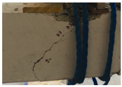 | Figure 22. Crack propagation in the prestressed beam, PC2, subject to impact |
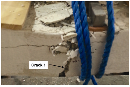
The prestressed beam with ULTRA-NET® fibers, mix UNH in Table 1, was tested under impact loading. Observations indicated that crack initiation occurred at 38 mm (1.5 in) drop height, which was similar to the value observed for plain concrete specimens. However, the length of the crack was measured to be 38 mm (1.5 in) which was noticeably shorter than similar values from plain concrete beams (Figure 23). Further, contrary to the first two PC specimens, the crack in this beam suggests a flexural nature, as it extended directly upward at 90-degree angle (Figure 24). Moreover, the width of the crack before failure was measured to be 1.422 mm (0.056 in), which is substantially smaller than the measured value for PC specimens. Close observations revealed that fibers bridged the crack and controlled the crack width (Figure 25). This fiber-reinforced beam showed compressive crushing under point loads, similar to previous specimens. The ultimate failure was recorded after drop height of 229 mm (9 in), which caused 145 kN (32.7 kip) impact load. This value is nearly 80 percent greater than the average resistance of plain concrete specimens. It should be noted that the beam was not broken to separate pieces as fibers bridged cracks.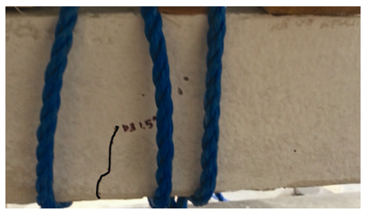 | Figure 23. Crack initiation in the fiber-reinforced prestressed beam, UNH, subject to impact |
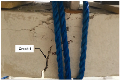 | Figure 24. Crack propagation in the fiber-reinforced prestressed beam, UNH, subject to impact |
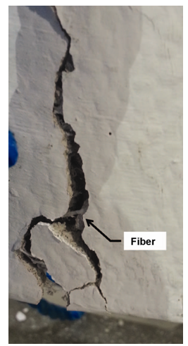 | Figure 25. Close-up of bridge action by fibers in an open crack of the fiber-reinforced prestressed beam, UNH |
 | Figure 26. Compressive crushing in concrete and failure of the fiber-reinforced prestressed beam, UNH, subject to impact |
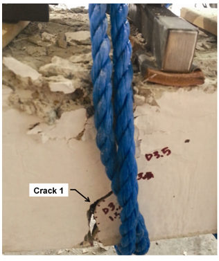
To compare the effect of fiber type on performance of prestressed beams, a fiber-reinforced prestressed beam with 3.32 % content by volume of FORTA-FERRO® fibers, FFH, was tested under impact loading. The crack initiation for this beam was similar to UNH specimen and occurred at drop height of 38 mm (1.5 in). The length of the crack was 25 mm (1.0 in), which is somehow consistent with the other fiber-reinforced specimen, UNH (Figure 27). The extension of this flexural crack at the bottom of the beam is shown in Figure 28. Further, Figure 29 shows the failure of the beam due to propagation of flexural crack at drop height of 203 mm (8.0 in). The corresponding load to this height is 137 kN (30.9 kip), which is 70% larger than the resistance of plain concrete specimens. The width of the crack was measured to be 3.25 mm (0.128 in). This indicates that FORTA-FERRO® fibers were as effective as ULTRA-NET® fibers in increasing the strength of the tested prestressed beams, but, not in reducing the crack width.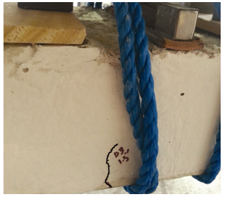 | Figure 27. Crack initiation in the fiber-reinforced prestressed beam, FFH, subject to impact |
 | Figure 28. Tensile crack at the bottom of the fiber-reinforced prestressed beam, FFH, subject to impact |
 | Figure 29. Failure of fiber-reinforced prestressed beam, FFH, subject to impact |
Another fiber-reinforced prestressed beam with 1.66% content by volume of FORTA-FERRO® fibers was tested to observe the effect of volume content on performance of specimens. The first two flexural cracks were developed at drop height of 25 mm (1.5 in) and 50 mm (2.0 in), with initial length of 25 mm (1 in) and 64 mm (2.5 in), respectively (Figure 30). The failure was recorded at 229 mm (9.0 in) drop height, when the crack width was measured to be 2.8 mm (0.112 in), as shown in Figure 31. These values are comparable with other fiber-reinforced specimens, despite the lower volume content of the fiber.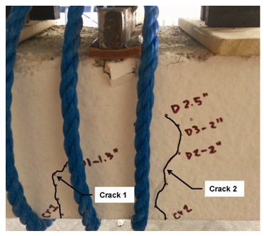 | Figure 30. Crack initiation in the fiber-reinforced prestressed beam, FFL, subject to impact |
 | Figure 31. Crack initiation in the fiber-reinforced prestressed beam, FFL, subject to impact |
5.5. Discussion
In the first part of experimental studies, eight compressive cylinders and four flexural beams were tested in the lab. Fiber reinforced specimens showed slightly higher peak strength and substantially larger ultimate displacement. These changes were proportioned to the volume content of fibers. In the second part of experimental investigations, the flexural behaviors of prestressed concrete beams without fibers were compared as they were subjected to static and impact loads. Both testing methods resulted in combination of flexural and shear cracks. However, the cracking strength of the beam was recorded to be higher under impact loading. Three fiber reinforced prestressed beams were subjected to impact loading in the third part of the experimentation. The first crack observed in these specimens was flexural crack. The fiber reinforcement did not have a significant impact on the cracking strength of the beam, but, it significantly reduced the crack length. Figure 32 compares the crack length for different beams subjected to impact load from 28 mm (1.5 in height), causing 60 kN (13.6 kip) equivalent static load.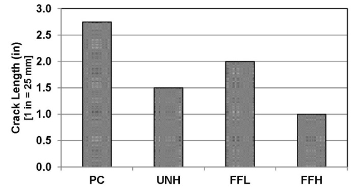 | Figure 32. Measured crack length for prestressed beams subject to impact from 38 mm (1.5 in) height |
There were mixed observations regarding the effect of fiber-reinforcement on crack width. In all prestressed beams, the crack width started out as a hair crack. The crack width in two prestressed beams with no fiber reinforcement had noticeable growth when the mass was dropped from 102 mm (4 in) height. Similar observations were made for the fiber-reinforced beams. However, the rates of growth in crack width were not the same, as ULTRA-NET® fibers appeared to effectively reduce the crack width before failure, but, FORTA-FERRO® fibers did not show such effect. Nevertheless, all fiber-reinforced beams sustained substantially greater impact loads in comparison to beams without fiber-reinforcement. The bridging action of fibers at open cracks was evident throughout the testing process. As a result, the final collapse of the beam was less brittle in fiber-reinforced beams in comparison to plain concrete beams, disregarding the size of the crack width. Moreover, the result of impact tests on fiber-reinforced beams with FORTA-FERRO® fibers showed that changing the fiber content from 1.66% to 3.32% does not have a substantial impact on cracking process.
5.6. Limitation
The implemented methodology relies on theoretical assumptions discussed in introduction and backgrounds, as well as practical limitations described in the methodology section of this paper. First, the interaction between various components of the track system, i.e., rail, tie, ballast, and subgrade is considered outside of the scope of this paper, as the paper is focused on crack propagation of concrete ties only. One of the major simplifications in the analytical and experimental studies was neglecting damping. While damping in structural components is not expected to be significant, it is present in testing mechanism. Thus, minimizing the damping effect was an essential part of the experimental studies.
5.7. Further Studies
Results of this study warrants expansion of experiments to additional fiber types and contents. Further, fiber-reinforcement can be investigated for other types of concrete ties and prestressing configurations.
6. Conclusions
Based on the experimental results and discussions, it is concluded that the addition of fiber can slow down the crack propagation of concrete ties. This conclusion is important for concrete ties subjected to impact loads caused by train wheel abnormalities. Furthermore, the bridging action of fibers enables prestressed concrete ties to sustain larger impact loads, even with larger crack width. These results may have immediate impact on the state of research, and ultimately, state of practice for design and construction of concrete ties. The improvement in performance of concrete ties will increase the life of the track and decrease the maintenance cost.
ACKNOWLEDGMENTS
The authors express their thanks to MidState Precast LP for donating fresh high strength concrete.
References
| [1] | American Concrete Institute (ACI) Committee 318. 2011. Building Code Requirements for Structural Concrete (ACI318-11) and Commentary (ACI318R-11). Farmington Hills, MI: ACI. |
| [2] | American Concrete Institute (ACI) Committee 544. 2002. State-of-the-Art Report on Fiber Reinforced Concrete. ACI 544.1R-96. Farmington Hills, MI: ACI. |
| [3] | American Railway and Maintenance-of-Way Association (AREMA). 2014. 2014 Manual for Railway Engineering. Lanham, MD: AREMA. |
| [4] | American Society for Testing and Materials (ASTM) Subcommittee C09.61. 2012. “Standard Practice for Making and Curing Concrete Test Specimens in the Field.” ASTM Standard C31. West Conshohocken, PA: ASTM International. |
| [5] | Ashour, Samir A., and Faisal F. Wafa. 1993. “Flexural Behavior of High-Strength Fiber Reinforced Concrete Beams.” ACI Structural Journal (90) 3, 279-287. |
| [6] | Chopra, Anil K. 2012. Dynamics of Structures. Upper Saddle River, NJ: Prentice Education Inc. |
| [7] | Dahlberg, Tore. 2006. “Track Issues.” In Handbook of Railway Vehicle Dynamics. Edited by Simon Iwnicki. Chapter 6. Boca Raton, FL: CRC Press. |
| [8] | Daniel, Laurent, and Ahmed Loukili. 2002. “Behaviour of High-Strength Fiber-Reinforced Concrete Beams under Cyclic Loading.” ACI Structural Journal (99) 3, 248-256. |
| [9] | Felton, L.P. and R.B. Nelson. 1997. Matrix Structural Analysis. New York, NY: John Wiley & Sons, Inc. |
| [10] | FORTA Corporation. 2014. Fibrillated Microfibers: ULTRA-NET® Grove City, PA: FORTA Corporation. [www.forta-ferro.com] |
| [11] | FORTA Corporation. 2014. Macrofibers: FORTA-FERRO® Grove City, PA: FORTA Corporation.[www.forta-ferro.com] |
| [12] | Hanna, A.N. 1979. “State-of-the-Art Report on Prestressed Concrete Ties for North American Railroads.” PCI Journal 24(5), 32-61. |
| [13] | Hibbeler, R. C. 2012. Mechanics of Materials. Upper Saddle River, NJ: Prentice Education Inc. |
| [14] | Kaewunruen, S., and A.M. Remennikov. 2009. “Impact Capacity of Railway Prestressed Concrete Sleepers.” Engineering Failure Analysis 16 (5), 1520-1532. |
| [15] | Kaewunruen, S., and A.M. Remennikov. 2010. “Dynamic Crack Propagations in Prestressed Concrete Sleepers in Railway Track Systems Subjected to Severe Impact Loads.” Journal of Structural Engineering 136 (6), 749-754. |
| [16] | Kaewunruen, S., and A.M. Remennikov. 2011. “Experiments into Impact Behavior of Railway Prestressed Concrete Sleepers.” Engineering Failure Analysis 18 (8), 2305-2315. |
| [17] | Kakooei, S., H.M. Akil, M. Jamshidi, and J. Rouhi. 2012. “The Effects of Polypropylene Fibers on the Properties of Reinforced Concrete Structures.” Construction and Building Materials. (27) 1, 73-77. |
| [18] | Lutch, R.H., D. K. Harris, and T. M. Ahlborn. 2009. “Prestressed Concrete Ties in North America.” 2010 AREMA Annual Conference and Exposition. Chicago, IL: AREMA. |
| [19] | Murray M.H., and Cai D. 1998. “Literature Review on the Design of Railway Prestressed Concrete Sleeper.” RSTA Research Report. Australia: RSTA. |
| [20] | RailCorp Network. 2013. Wheel and axles reference manual. ESR 0331, Engineering Standard Rolling Stock. New South Wales, Australia: RailCorp Network.[www.asa.transport.nsw.gov.au]. |
| [21] | Szepe, F. 1991. Load Distribution Capacity of Railway Superstructure. PeriodicaPolytechnica Civil Engineering 35 (3-4), 205-224. |
| [22] | Timoshenko, S. and J.M. Gere. 1972. Mechanics of Materials. New York, NY: Van Nostrand Reinhold Co. |
| [23] | Transportation Safety Board of Canada (TSB). 1996. Railway Occurrence Report: Derailment. Report Number R96T0095. Gatineau, QC, Canada: TSB. [http://bst-tsb.gc.ca] |
| [24] | Wakui, H., and H. Okuda. 1999. “A Study on Limit State Design Method for Prestressed Concrete Sleepers.” Concrete Library of Japan Society of Civil Engineers (33) 1, 1-25. |
 Abstract
 Reference
 Full-Text PDF
 Full-text HTML