Bayar J. Al-Sulayvani, Diyar N. Al-Talabani
Department of Civil Engineering, University of Mosul, Mosul, Iraq
Correspondence to: Diyar N. Al-Talabani, Department of Civil Engineering, University of Mosul, Mosul, Iraq.
| Email: |  |
Copyright © 2014 Scientific & Academic Publishing. All Rights Reserved.
Abstract
The main purpose of this study is to evaluate the effect of CFRP strips on the behavior of circular RC slabs which have different shapes of openings (circle, square, and rectangle). Eight circular RC slabs were constructed and tested under repeated loading. The experimental variables considered in this paper include the shape of openings and the form of strengthening. All the slabs were geometrically similar, having dimensions of (1200mm in diameter and 75mm in thickness). Two different strengthening schemes were used in this paper. The slab specimens were divided into three groups: group I includes three unstrengthened control slabs with central openings, group II includes three specimens having central openings and strengthened with CFRP strips using scheme I, and group III includes two specimens having central openings and strengthened with CFRP strips using scheme II. The test results clearly demonstrated that using CFRP leads to significant improvement in the flexural capacity of circular RC slabs.
Keywords:
Reinforced Concrete, Circular Slabs, Repeated Loads, Carbon Fiber Reinforced Polymer CFRP
Cite this paper: Bayar J. Al-Sulayvani, Diyar N. Al-Talabani, Strengthening of Circular RC Slabs with Central Openings Using CFRP Stripsunder Repeated Loading, Journal of Civil Engineering Research, Vol. 4 No. 3, 2014, pp. 51-58. doi: 10.5923/j.jce.20140403.01.
1. Introduction
In existing reinforced concrete structures it is very often required to create openings in the slabs to accommodate new stair wells, elevators shafts, utility ducts, and also required for plumbing fire protection pipes, heat and ventilation ducts and air conditioning. Hence, problem becomes more complex when openings are planned to be made in existing slabs [1].Introducing openings in slabs can severely weaken the slabs due to the cut out of both concrete and reinforcing steel [2]. The traditional material used in the strengthening of concrete structures is steel. Because of its drawbacks of low corrosion resistance and of handling problems involving excessive size and weight, there is need for the engineering community to look for alternatives. Due to lightweight, high strength, good fatigue, and corrosion properties, fiber reinforced polymer (FRP) have been intensively used in the repair and strengthening of concrete structures [3].The principal aims of this research are summarized as follows:1- Investigating experimentally the effect of openings on the ultimate loads and cracks pattern. The simply supported restraint of pin is applied at all edges of circular slabs and repeated loads were applied through annular load at the center of slabs.2- Investigating the structural responses of CFRP strengthened circular RC slabs under repeated loading.3- Investigating experimentally the effectiveness of using CFRP strips externally bonded to the tension face of the slabs around the openings to strengthen circular reinforced concrete slabs with openings against flexural failure.
2. Experimental Program
During this research, the study of the behavior of slabs was based upon eight circular RC slab specimens. All the specimens have dimensions of (1200mm in diameter and 75mm in thickness) and concrete compressive strengthequal to (30MPa) at age of 28 days. All slab specimens were reinforced by one bottom layer of (6mm in diameter) steel bars spaced at 150mm c/c in x and y directions and arranged to give a clear concrete cover of (15mm). The slab specimens were assumed to be simply supported on the all edges and tested under repeated loads. The openings were not bordered with reinforcement as is used. This condition was imposed in order to find out which is the quantum when bordering is passed over and the cut in slab is made on site without accounting the possible loss of strength in the control perimeter. The reinforcement details of the specimens are shown in figure (1).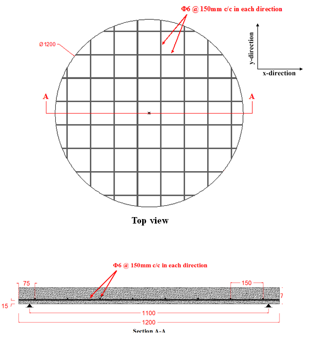 | Figure 1. Reinforcement Details of the Slab Specimens (All Dimensions in mm) |
2.1. CFRP Strengthening Schemes
Two different strengthening schemes were used in this paper. The amount of CFRP used in both schemes was approximately equal in order to evaluate the effect of the arrangement of CFRP strips on strengthening of circular RC slabs with central openings against flexural failure.In scheme I, the CFRP flexible unidirectional sheets were cut into strips with width equal to thickness of the slab specimens (75mm). The CFRP strips were applied in one layer to the lower face (tension face) of the circular RC slabs as supplementary tension reinforcement around the openings in two orthogonal directions, parallel to the directions of internal grid reinforcement.Same procedure of scheme I was followed in scheme II but the CFRP strips were applied perpendicular to the direction of expected crack which started from the corner of square and rectangular openings.In order to avoid bond failure of the CFRP strips, in both schemes, the CFRP strips were extended along the full dimensions of the circular slabs.
2.2. Specimens Description
In this paper, three control RC slabs without strengthening and five CFRP strengthened RC slabs were tested. The parameters considered in this study are as follows: strengthening schemes of circular RC slabs by CFRP strips and the shape of openings in the circular RC slabs with equal size.The test specimens are divided into three series:Series I includes three unstrengthened control slab specimens having different shapes of central openings, called to these specimens (A-1, C-1, and E-1). A-1 specimen with circular opening of (150mm in diameter), C-1 specimen with square opening of dimensions (133×133mm) E-1 specimen with rectangular opening of dimensions (103×172mm).Series II includes three specimens having different shapes of central openings and strengthened with CFRP strips using scheme I and called to these specimens (A-2, C-2, and E-2). A-2 specimen with circular opening of (150mm in diameter) and strengthened by CFRP strips in parallel to the directions of internal grid reinforcement, C-2 specimen with square opening of dimensions (133×133mm) and strengthened by CFRP strips in parallel to the directions of internal grid reinforcement, E-2 specimen with rectangular opening of dimensions (103×172mm) and strengthened by CFRP strips in parallel to the directions of internal grid reinforcement.Series III includes two specimens having different shapes of central openings and strengthened with CFRP strips using scheme II and called to these specimens (C-3 and E-3). C-3 specimen with square opening of dimensions (133×133mm) which was located at the center of circular slab and strengthened by CFRP strips in perpendicular to the directions of expected cracks which started from the opening corners, E-3 specimen with rectangular opening of dimensions (103×172mm) which was located at the center of circular slab and strengthened by CFRP strips in perpendicular to the directions of expected cracks which started from the opening corners.
3. Materials Properties
3.1. Cement
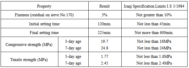
Ordinary Portland cement (Type I) of BADOSH mark was used in casting all the slabs. It was kept in a dried place to avoid atmospheric damaging conditions. The chemical and physical analyses of the used cement are given in tables (1) and (2), respectively. The properties are conformed to the Iraqi Standard Specification (IS-No.5, 1984) [4].| Table 1. Chemical Composition of Cement [4] |
| | Oxides | Content (%) | Iraqi Specification Limits I.Q.S 5/1984 (%) | | CaO | 61.8 | 60.0-67.0% | | SiO2 | 23.4 | 17.0-25.0% | | AL2O3 | 5.4 | 3.0-8.0% | | MgO | 3.5 | 5.0% max. | | Fe2O3 | 3.25 | 0.5-6.0 | | SO3 | 2.25 | 2.8% max. | | Compound Composition | | C3S | 38.53 | 31.03-41.05% | | C2S | 33.45 | 28.61-37.90% | | C3A | 11.99 | 11.96-12.30% | | C4AF | 7.92 | 7.72-8.02% |
|
|
Table 2. Physical Properties of Cement
 |
| |
|
3.2. Fine Aggregate
River sand was used as fine aggregate. The sand was washed and cleaned with water several times, later it was spread out and left to dry in the air. The fine aggregate was then sieved at sieve size of (4.75mm) to separate the aggregate particle of diameter greater than (4.75mm), after which it was ready for use. The obtained results indicated that the fine aggregate grading was within the limits of ASTM C33-99a [5] as shown in table (3).| Table 3. Grading of Fine Aggregate |
| | Sieve size (mm) | Passing (%) | ASTM C33-99a | | 10 | 100 | 100 | | 4.75 | 98 | 95-100 | | 2.36 | 83 | 80-100 | | 1.18 | 64 | 50-85 | | 0.6 | 42 | 25-60 | | 0.3 | 20 | 5-30 | | 0.15 | 5 | 0-10 |
|
|
3.3. Coarse Aggregate
Crushed gravel was used throughout this work within maximum size of (19mm). It was washed and cleaned by water several times and left to dry in the air. Two tons from coarse aggregate were sieved on four sieves (4.75, 9.0, 12.5, and 19.0mm) and then remixed to satisfy the requirements of ASTM C33-99a [5] as shown in table (4).| Table 4. Grading of Coarse Aggregate |
| | Sieve size (mm) | Passing (%) | ASTM C33-99a | | 25.0 | 100 | 100 | | 19.0 | 95 | 90-100 | | 12.5 | 38 | 20-55 | | 9.0 | 8 | 0-15 | | 4.75 | 0 | 0-5 |
|
|
3.4. Mixing Water
Ordinary clean tap water was used for casting and curing all the slabs.
3.5. Steel Reinforcement
Deformed steel bars of size (6mm in diameter) were used as reinforcement to test slab specimens. Three specimens of these bars were tested under tension according to ASTM C370-05 [6]. The yield stress and the ultimate strength are (598MPa) and (657MPa), respectively. The tensile tests were performed using the testing machine available at the Construction Materials Laboratory of Civil Engineering Department, Mosul University.
3.6. Carbon Fiber Reinforced Polymer CFRP
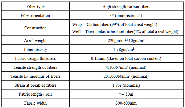
The CFRP reinforcement used in the strengthening of circular RC slabs was SikaWrap 230C unidirectional flexible sheets which were provided by Sikacorporation as shown in figure (2). The tensile behavior characterized by a linearly elastic stress-strain relationship up to failure, which is sudden and can be catastrophic. The technical properties of SikaWrap 230C as given by the manufacturer are presented in table (5) [7].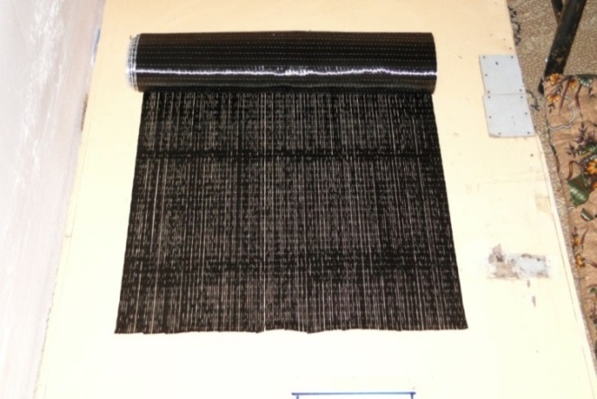 | Figure 2. SikaWrap 230C |
Table 5. Properties of SikaWrap 230C [7]
 |
| |
|
3.7. Bonding Material
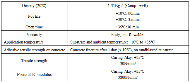
The building and construction industries presented some of the largest types of adhesive materials, many applications are non-structural in the sense that the bonded assemblies are not used to transmit or sustain significant stresses (e.g. crack injection and sealing, skid-resistant layers, bonding new concrete to old). Structural application implies that the adhesive is used to provide a shear connection between similar or dissimilar materials, enabling the components being bonded to act as a composite structural unit [8].The epoxy resin (Sikadur 330) as shown in figure (3) used in this paper was also provided by Sika corporation. The epoxy consists of two components; part A is in white, part B is in dark gray. The mix ratio of part A and part B is four to one by weight. The properties are also given in table (6) [9].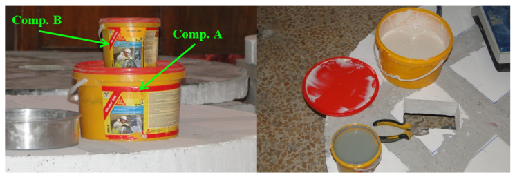 | Figure 3. Sikadur 330 |
Table 6. Properties of Sikadur 330 [9]
 |
| |
|
4. Preparation of Test Slabs
4.1. Mix Design
Several trial mixes were made until the following proportion by weight of (1 cement: 1.8 sand: 2.8 gravel) with water cement ratio 0.45 and the slump was (120mm) was found to be sufficient to obtain the average compressive strength of (30MPa) in all cylindrical specimens which were tested at age of 28 days. Mixture details are given in table (7).| Table 7. Properties of Concrete Mix |
| | Parameter | Amount | | Water/Cement ratio | 0.45 | | Water (kg/m3) | 180 | | Cement (kg/m3) | 400 | | Fine aggregate (kg/m3) | 720 | | Coarse aggregate (kg/m3) | 1120 |
|
|
4.2. Mixing, Casting, and Curing of the Slabs
Eight slab specimens were casted and cured under laboratory conditions at the Construction Materials Laboratory of Civil Engineering Department, Mosul University. The modeling mortar concrete casting and curing procedure is described below.1- Steel mold were treated with oil before putting the reinforcement cage to prevent adhesion with concrete after hardening.2- Placing the required steel grid reinforcement in the steel mold. The clear concrete cover of (15mm) was maintained by using plastic spacers.3- Before mixing, all quantities were weighed and packed in a clean container.4- Prior to starting rotation of the mixer, the interior surface of mixer was cleaned and moistened before placing the mix contents.5- The mixer was started and then added the aggregate, cement, and water with mixing running.6- Steel bars for each slab specimen were placed in their correct positions and the specified protection cover was checked.7- Concrete was poured in the steel molds in three layers, and each layer was compacted using electrical handle vibrator. The cylindrical molds were filled with concrete into three equal layers. Each layer was vibrated on a table vibrator for 30 seconds. The upper surface of concrete was smoothly finished after casting was completed using hand trowel. All slab specimens and concrete cylinders were left in the laboratory until they were demoulded after 24 hours.8- Slab specimens were removed from their molds and then burlap sacks were placed over the slabs and wetted down until the fully 28 days had passed. The cylindrical concrete specimens were placed in a container filled with tap water for 28 days. After the period of water curing 28 days had passed, the slab specimens were painted by white emulsion to ensure clear appearance of crack growth. Figure (4) shows the equipment and curing procedure.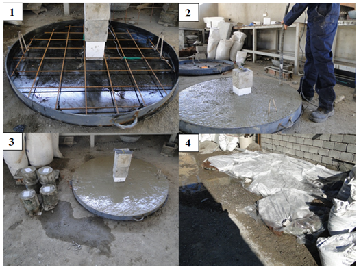 | Figure 4. Equipment and Curing Procedure |
5. Description of Testing Rig
The testing machine is shown in figure (5). The steel work setup for the testing machine includes two main parts:- The main frame: It consists of two vertical steel columns (C-section 300×100×10mm), the upper bed (two channels, C-section 300×100×10mm), the lower bed (four channels, C-section 300×100×10mm), and two bottom supporting beams (I-section 800×300×25mm) connected at the bottom of columns to support the testing frame on the ground. The vertical hydraulic jack was installed in the middle of the upper bed through a steel plate (700×400×30mm) attached to the bottom of the two C-channels. In order to transmit the load from hydraulic jack to the circular slab, a number of plates with different shapes were used. The cylinder of hydraulic jack (180mm in diameter) was connected to hand-pump in the hydraulic machine by hose. Also, the load cell was installed and attached to the bottom face of hydraulic jack. The jack was operated using the valve of hydraulic oil and load cell was connected to a data logger TDS-530 for recording the applied repeated loads.- The supporting frame: All circular slabs were tested under repeated loads and supported on the steel frame which it consists of circular ring shaft of (1100 mm in diameter) with (circular-section 40mm in diameter) and a number of curved shafts (square–section 40×40mm) which were distributed along the circumference of circular ring shaft in order to allow the rotation between two shafts and also to prevent local failure at the supporting points as shown in figure (6). The loading support for the different shapes of openings is shown in figures (7) through (9). 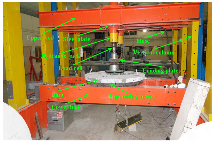 | Figure 5. Testing Machine |
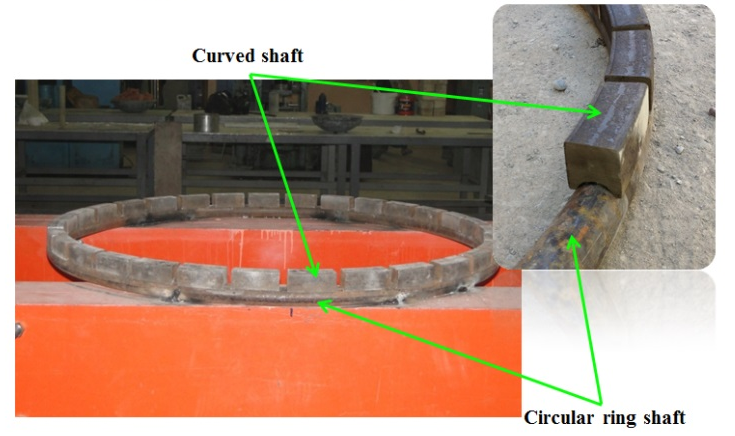 | Figure 6. Supporting Frame |
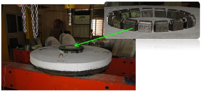 | Figure 7. Loading Support Condition of Circular Slab with Circular Opening |
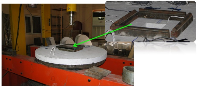 | Figure 8. Loading Support Condition of Circular Slab with Square Opening |
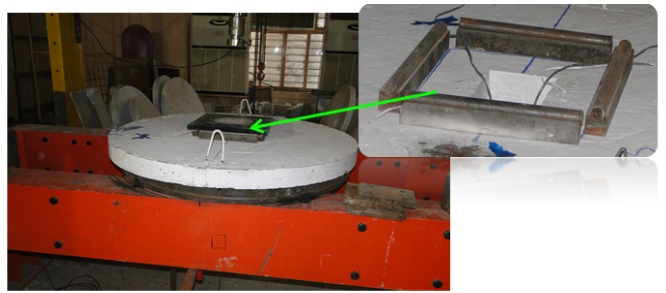 | Figure 9. Loading Support Condition of Circular Slab with Rectangular Opening |
6. Description of Applied Repeated Loads
Concrete behavior subjected to repeated loads is differ than the one subjected to static loads. Repeated loads caused crushing in some part of concrete due to loading and unloading process. The repeated loads were applied to the circular RC slabs through annular load subjected at the center of slabs and for many cycles which were started from (5KN) with increment of (5KN) for each cycle up to failure by using a hydraulic jack of (1000kN) capacity. Figure (10) shows the history of applied repeated loads.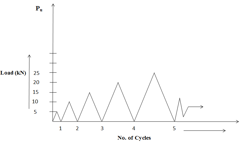 | Figure 10. The History of Applied Repeated Loads |
7. Testing Procedure
Before the day of testing, the lines of supports and points at which the deflection was measured were marked.On the day of testing, circular slabs were placed inside the testing machine so that support linesand LVDTs were fixed in their correct locations and then LVDTs and load cell were connected to data logger TDS-530 as shown in figure (11). | Figure 11. Data Logger TDS-530 |
The first step was to zero load cell and record instrument readings. At each loading stage, the test measurement included the magnitude of applied load that was measured in Kilo Newton and deflection at the center of slab specimens that was measured in millimeter.At end of the test, the crack pattern and mode of failure for each slab were carefully examined.
8. General Behavior and Cracks Pattern
Under repeated loads, the cracks first started with radial cracks running from the corners of the square and rectangular openings and from the perimeter of the circular opening toward the slab edges on the tension surface of the circular slabs. As the load was increased, circumferential cracks occurred below the area of loading support and developed gradually over the entire slabs. The formation of inclined shear cracks was visible inside the openings during testing of circular RC slabs at an angle approximately (25-70) degrees. The inclined shear cracks usually started from the flexural cracks.The presence of CFRP strips delays the crack initiation and arrested their propagation. Also, distinct reduction was observed in the number and width of cracks. As the load increased, more radial cracks developed and extended toward the slab edges.The cracks pattern at the tension surface of unstrengthened (control) and strengthened circular slabs are shown in figures (12) through (14).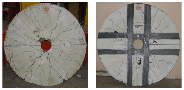 | Figure 12. Cracks Pattern for Circular Slabs with Circular Openings |
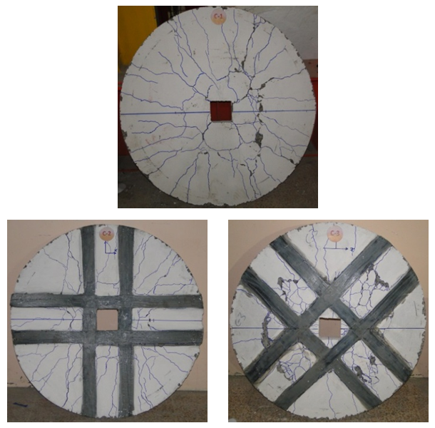 | Figure 13. Cracks Pattern for Circular Slabs with Square Openings |
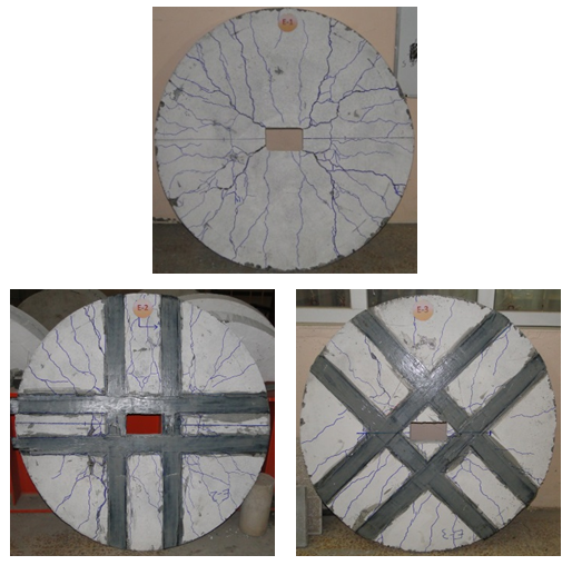 | Figure 14. Cracks Pattern for Circular Slabs with Rectangular Openings |
9. Load-Deflection Response
Figures (15) through (18) compare the normalized load- central deflection response of all eight tested specimens. In general, the normalized load-central deflection response can be divided into uncracked and cracked stages. The uncracked stage is characterized by an approximately linear relationship between the load and the central deflection and both the concrete and steel behave essentially elastic the cracked stage can be divided into two substages: a preyield stage and a postyield stage. The preyield cracked stage is from the cracking load to the yield load. The postyield cracked stage extends from the yield to the failure load. In general, unstrengthened (control) slab specimens, a large increase in deflection were noticed in a comparison with strengthened slab specimens.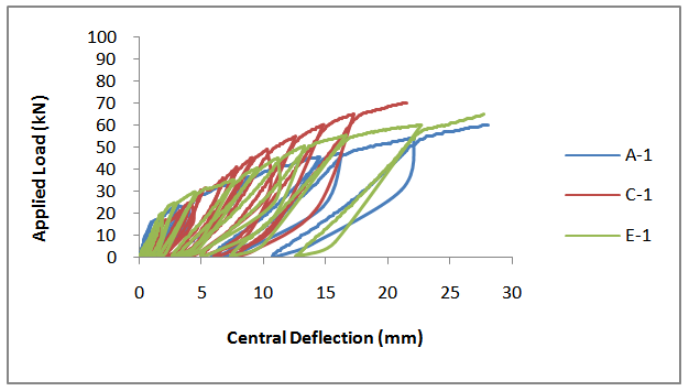 | Figure 15. Load-Deflection Curve for Unstrengthened (Control) Circular Slabs |
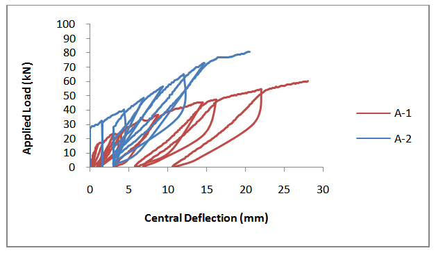 | Figure 16. Load-Deflection Curve for Unstrengthened (Control) and Strengthened Circular Slabs with Circular Openings |
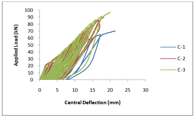 | Figure 17. Load-Deflection Curve for Unstrengthened (Control) and Strengthened Circular Slabs with Square Openings |
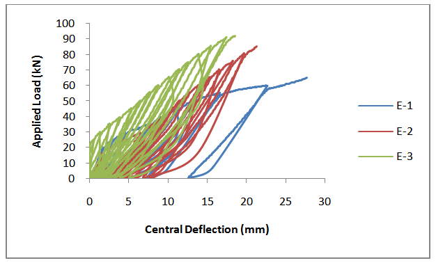 | Figure 18. Load-Deflection Curve for Unstrengthened (Control) and Strengthened Circular Slabs with Rectangular Openings |
10. Conclusions
1- The presence of CFRP strips on the tension face of circular slabs delays the cracks initiation and arrested their propagation. Also, distinct reduction was observed in the number and width of cracks.2- In general, it can be seen that the increases in the ultimate loads for specimens that were strengthened using scheme II are greater than those for specimens that were strengthened using scheme I, that may be due to the orientation of the CFRP strips are perpendicular on the inclined crack.3- The strengthened specimens exhibit much stiffer responses and lower deflections than the corresponding unstrengthened (control) specimens.4- For the tested circular slabs with square openings and subjected to the repeated loads, the ultimate flexural loads were greater than the circular slabs with circular and rectangular openings, respectively.5- The test results clearly demonstrated that using CFRP leads to significant improvement in the flexural capacity of circular RC slabs. Depending on the CFRP strengthening scheme used, the ultimate load capacity was increased by 28.57% to 41.54%.
References
| [1] | Mota, M.C. and Kamara M. “Floor Openings in Two-Way Slabs, Concrete International Journal”, Vol.28,07, July 2006,pp. 33-66. |
| [2] | Muhammed, N.J. “Experimental Study of Self Compacting RC Slabs with Opening Strengthening with Carbon Fiber Laminated and Steel Fiber”, Vol. 16, No. 1, March 2012, pp. 54-74. |
| [3] | Hsuan, T.H., Fu, M.L., and Yih, Y.J. “Nonlinear Finite Element Analysis of Reinforced Concrete Beams Strengthened by Fiber-Reinforced Plastics”, Journal of Composite Structures, Vol. 63, 2004, pp. 271-281. |
| [4] | Iraqi specification No.05, "Portland Cement", Baghdad, Iraq, 1984, (In Arabic). |
| [5] | American Society of Testing and Materials (ASTM). “Standard Specification for Concrete Aggregates”, ASTM C 33 – 99a, West Conshohocken, PA, 1999a. |
| [6] | ASTM Designation C370-05a, (2005) "Standard Specification for Testing Method and Definitions for Mechanical Testing of Steel Products", 2005 Annual Book of ASTM Standards, American Society for Testing and Material, Philadelphia, Pennsylvania, Section 1, Vol. (1.01), pp. 248-287. |
| [7] | SikaWrap 230C (2009), “SikaWrap-230 C/45: Woven Carbon Fiber Fabric for Structural Strengthening”, Product &Technical Data Sheet, Sika Company, Istanbul Branch, Turkey. |
| [8] | Mohammed, K.I. “Behavior of RC Beams Strengthened with CFRP Under Combined Actions” Ph.D. Thesis, Civil Engineering Department, University of Mosul, 2011, pp.181. |
| [9] | Sikadur 330 (2008), “Sikadur-330: 2-Part Epoxy Impregnation Resin”, Product & Technical Data Sheet, Sika Company, Istanbul branch, Turkey. |
 Abstract
 Reference
 Full-Text PDF
 Full-text HTML