-
Paper Information
- Next Paper
- Paper Submission
-
Journal Information
- About This Journal
- Editorial Board
- Current Issue
- Archive
- Author Guidelines
- Contact Us
Journal of Civil Engineering Research
p-ISSN: 2163-2316 e-ISSN: 2163-2340
2014; 4(2): 33-41
doi:10.5923/j.jce.20140402.02
The Investigation of Permanent Displacement in Structures with Buckling-Resistant Braces under Impact Loading in Two Joint Bracing Systems of BF and Dual
 Abstract
 Reference
 Full-Text PDF
 Full-text HTML
M. Ali Lotfollahi Yaghin1, M. Reza Bagerzadeh Karimi2, R. Mehdi Nezhad3, V. Sadeghi Balkanlou2
1Prof. of Faculty of Civil Engineering, University of Tabriz, Iran
2Young Researchers and Elite Club, Tabriz Branch, Islamic Azad University،Tabriz،, Iran
3Department of Civil Engineering, Islamic Azad University, Maraghe Branch, Iran
Correspondence to: M. Reza Bagerzadeh Karimi, Young Researchers and Elite Club, Tabriz Branch, Islamic Azad University،Tabriz،, Iran.
| Email: |  |
Copyright © 2014 Scientific & Academic Publishing. All Rights Reserved.
Repeated damage to frames with concentric bracings in recent earthquakes such as the 1984 Mexico City earthquake, 1989 Loma Prieta, and 1994 Northridge intensified the concerns about the ultimate ductility capacity of this class of structures. Several categories were mentioned for the poor performance of this class of braced frames. In this paper, a three-story steel structure in three dimensions is raced with buckling-resistant braces and then a dynamic analysis was applied to it. Then the results of application of buckling-resistant braces to dual system for reducing permanent deformation under impact loading have been investigated. Finally, the impact of imperfection in protective cover upon the performance of brace is studied. The results are indicated in tables and figures, hence being compared.
Keywords: Buckling-resistant brace, Dual system frame (Dual), Impact loading, Dynamic load
Cite this paper: M. Ali Lotfollahi Yaghin, M. Reza Bagerzadeh Karimi, R. Mehdi Nezhad, V. Sadeghi Balkanlou, The Investigation of Permanent Displacement in Structures with Buckling-Resistant Braces under Impact Loading in Two Joint Bracing Systems of BF and Dual, Journal of Civil Engineering Research, Vol. 4 No. 2, 2014, pp. 33-41. doi: 10.5923/j.jce.20140402.02.
Article Outline
1. Introduction
- Repeated damage to frames with concentric bracings in recent earthquakes such as the 1984 Mexico City earthquake, 1989 Loma Prieta, and 1994 Northridge intensified the concerns about the ultimate ductility capacity of this class of structures. Several categories were mentioned for the poor performance of this class of braced frames. For example, the typical braces often have ductility with limited energy dissipation capacity under cyclic load. Therefore, a new system resistant to lateral_ a system of frame with buckling-resistant brace was studied in the U.S. in 1994. The buckling-resistant braces show good energy dissipation characteristics. However, the low re-indurations of these braces make the system vulnerable to damage and unfavorable behavioral characteristics such as large displacement.As noted above, the use of low-strength steel in the core of buckling-resistant braces has some advantages compared to other types of steels. This advantage for low-strength steel is due to the following main reasons:1- High energy waste (high CPD)2- High ductility3-The low stress of bracing components in the columnsAlthough the above factors are very desirable advantages for buckling-resistant brace made of soft steel core, the use of soft steel causes a very important undesirable behavior in the structure which is permanent displacement in the structure. According to the research conducted by Sabelli, this permanent displacement is about 40% to 60% of the maximum displacement [1]. One of the proposed mechanisms to reduce this permanent displacement is by adding the previously mentioned supporting bending frame. In this study, the permanent displacement in a steel joint structure with buckling-resistant bracing whose core is made of soft steel (yield stress 100 Mpa) under impact loading is investigated and the effect of adding supporting moment frame on the rate of permanent displacement under impact load is assessed. The impact of support moment frame upon ductility of structure will be investigated as well. Because, adding bending frame should not have a great effect on ductility of the main structure.Testing of metal brace covered with mortar inside the metal tube was carried out by Kimureat. The tube filled with mortar proved to be effective against the buckling of the core. In the subsequent investigation, 4 samples were tested with the actual sizes under seismic load. They indicated that if the ratio between the buckling strength of elastic outer shield and the yield strength of the core brace is greater than 1.9, no buckling occurs in the core of brace and that testing sample did not show good hysteresis. Iwata et al, in 2004 [2], studied the periodic performance of some of the existing anti-buckling braces in Japan. Three large-sized braces were tested by BRB at University of Berkely to help design and construct buildings.Black et al, in 2002 [3], did a different analysis on actualization of internal core stability in the great earthquakes and elastic torsional buckling of core. Chen found out that application of metal with low resistance makes possible the yield of the brace with low flexural deformation, hence more ductility is achieved. In a study conducted by Uang, the advantage of application of BRB in the dual system for reducing the permanent deformation was investigated [4].Tsai and Lai, in 2005, studied the impact of friction reducers on the periodic response of braces [5]. Sabelli increased the seismic absorption of frames by coating bracing system. Kim et al, [6-8], provided a seismic design process for BRBF based on energy waste and a direct displacement design process.In this paper, behaviour of the lateral load resistance systems such as bracing systems have been studied under buckling, and also its behaviour have been studied under the impact of loading. Then, designing method has been investigated under the impact loading. The results gained from dynamic analysis can be observed in the diagrams of displacement of stores and the displacements between stores which have been illustrated in figures.
2. Modeling and Analysis
- In order to check the accuracy and precision of the modeling and comparing the results with designing goals, dynamic analysis using finite element software ABAQUS was carried out [9]. A three-story steel structure in three dimensions is raced with buckling-resistant braces and then a dynamic analysis was applied to it.Since the design of these types of structures, namely the metal frames braced with buckling resistant braces, is based on the principle that the beams and columns remain absolutely elastic in earthquake and seismic load is wasted by braces and dual system, thus the design of structure is limited only to the design of braces and the beams and columns which are designed for gravity load and the component load of braces, will be the same in all samples, and the only difference between the four different models is the size of braces with other elements and structural characteristics being the same in all aspects.
2.1. Introduction of Structure
- The structure under study is a three-storey structure, once modelled as a simple building frame with buckling-resistant brace and once as a dual system meaning a simple building frame with buckling-resistant brace by adding moment frame. In this study, a three-dimensional structure has been modeled. Cross-Sections of beams, columns and braces are represented in Table (1) and (2).The figure (1) indicates the placement of braces and moment frame. As it can be observed, in each plan there are 4 braced spans and also, in dual system (Figure 1-B) there are 4 braced spans with a moment frame. Regards that the stress caused in the structural members is within the acceptable limit, the members of the moment frame are selected as similar to the members of joint frame. Since the software used (ABAQUS) is not a designing-software, the ratio between the number of moment frames with that of joint frames and the number of buckling-resistant braces is not very ideal. But, by using suitable design software it can be achieved with an optimal ratio between them so that adding moment frame would have the least impact ductility of structural and the highest impact upon reducing permanent displacement. Thus, this study merely deals with the impact of adding supporting moment frame to the structures with buckling-resistant braces under the impact load, while the aim of this study is not to provide a proper ratio between the number of joint frames with buckling-resistant braces and the number of moment frames.
|
|
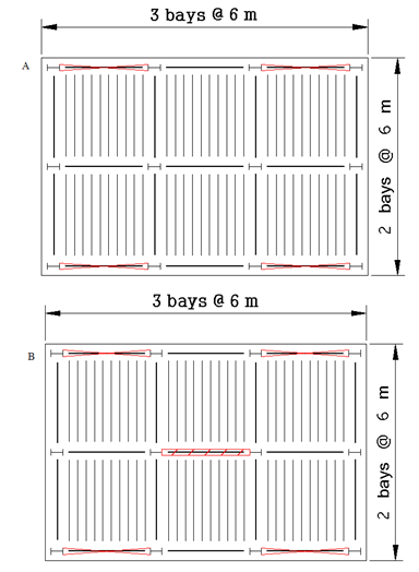 | Figure 1. Plan of Structures A) Joint frame with buckling-resistant brace (BF), B) Dual system frame (Dual) |
2.2. Introduction of Impact Loading for the 3D Structure
- Figure (2) shows a 3-D image of the structure modeled by ABAQUS. The altitude of all stories equals 4 meters. Impact load was applied to the structure in two triangular and rectangular forms so that each had a different intensity. In this section, the load values were chosen so that all the elements of the area under diagram of load-time are constant. The load values for both triangular and rectangular shapes are observed in tables (3) and (4).As can be observed in the following tables, the load values is the same for triangular and rectangular loads whereas the values of impact force time for rectangular load is half of that of triangular load.
 | Figure 2. The 3D Image of Structure |
|
|
2.3. The Results of Analysis and Comparison of Results
- By modelling 3D structure and application of impact load and after vibration of structure, the values of maximum displacement and permanent displacement for Case 1 are presented in Figure (3).As observed, the structures under impact load after reaching maximum displacement is vibrated and eventually the structure reaches quiescent state. Since the members of structure are connected to each other through joints, and the whole length of core brace yields entering in the plastic phase, the structure has permanent displacement after reaching quiescent state which is indicated in the figure (3). To fix this defect, supporting moment frame has been used. In the following, the impact of adding supporting moment frame on the performance of braces is shown in the diagram.
 | Figure 3. The Diagram of Displacement Level of Three Stories under impact loading (BF) |
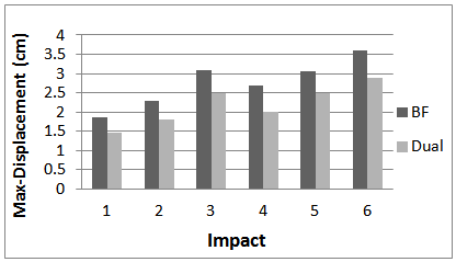 | Figure 4. The Diagram of Ratio of Maximum Displacement |
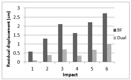 | Figure 5. The Diagram of Ratio of Permanent Displacement |
 | Figure 6. The Diagram of the Ratio between impact Intensity and Permanent displacement |
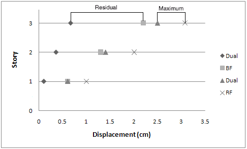 | Figure 7. The Ratio of Maximum Displacement and Permanent Displacement along the Height of Building |
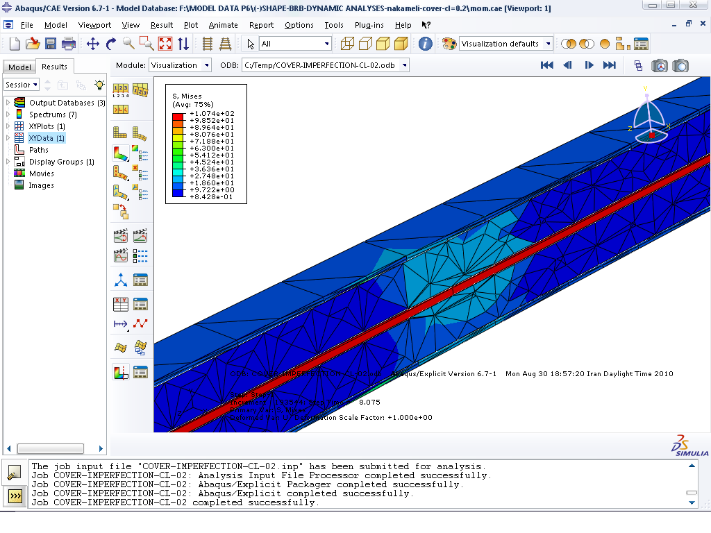
3. The Impact of Geometric Imperfection upon the Behavior of Buckling-Resistant Braces
- As previously mentioned, the core of buckling-resistant braces is considered as one of the most important and critical parts of this type of braces. It was previously observed that the core of buckling-resistant braces bears the entire axial load and outer shield prevents buckling of the core and it should not share a part of the endurance of axial load. But, the point which merits investigation is as to what will be the behavior of the brace with geometric imperfection in the coating of the brace and what will be the impact of behavior of core of brace and resistant-buckling cover upon one another's performance. The geometric imperfection in the cover of buckling-resistant braces is perhaps due to the slow set mortar being curved. In fact, the necessity of study is this point that as to what extent we can rely on the outer shield as a mechanism for the same behavior of brace in tension and compression and as to how much we should be careful in making the cover of buckling-resistant braces.To investigate this point, a brace with a strong outer shield but with geometric imperfection is modeled and the behavior of brace under dynamic load is analyzed. At first, a kind of buckling-resistant brace is modeled and put under dynamic load, and after determining the behavior and making sure of modeling by creating geometric imperfection on the cover, the behavior of brace is investigated again.
3.1. Modeling of Buckling-Resistant Brace
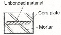
- Here the characteristics of a type of buckling-resistant brace are introduced. This brace is made up of the main parts of core, protective cover, separating material, and connector. The figure (8) shows a cross section of the brace.
 | Figure 8. Cross Section of Buckling-Resistant Brace |
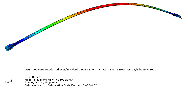 | Figure 9. The First Mode of Buckling |
 | Figure 10. The Way of Contact between Core and Cover |
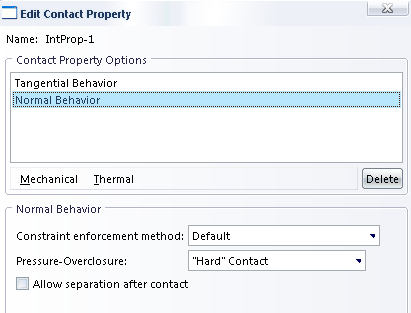 | Figure 11. The Characteristics of Contact between Core and Cover |
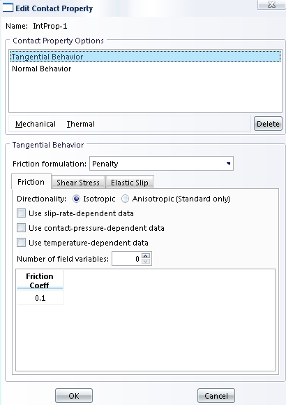 | Figure 12. The Friction Coefficient Related to the Areas in Contact |
 | Figure 13. The Time Record of Axial Displacement of Core |
 | Figure 14. The Stress-Strain Curve of Brace |
3.2. Introduction of the Shape of Geometric Imperfection
- As is observed in Figure (15), it is assumed that the mortar inside protective cover is curved toward and the empty space or gap between the core and the mortar has decreased.
 | Figure 15. The Details of Geometric Imperfection |
3.3. The Results of Analysis
- By doing a dynamic analysis for all cases A, B, and C, the values of compressive and tensile strain were obtained. The values related to the stress in the members of brace can be observed too. As indicated in the figure (16) which has been developed for the Case A, in the region of geometric imperfection, the stress of protective mortar was highly increased and the mortar was ruptured because of transfer of stress from the core of brace to protective mortar.
 | Figure 16. Stress in Members of Brace |
 | Figure 17. Ratio of Difference between Strains in Tension and Compression |
 | Figure 18. Ratio of Maximum Tensile Strain to Compression Strain |
4. Conclusions
- In this study, the process of seismic design based on performance was investigated for structures with buckling-resistant braces by joint connection of the beam to column. The proposed design process, assumes a straight line for the shape of storey displacement, the type of cutting, and the shape of main mode. The performance of structure of the model designed to displace the target was evaluated under impact loading by dynamic analysis in order to check as to whether or not the objective of the operation has been achieved.According to the numerical results, the diagram of maximum displacement diagram is close to the line and the displacement between stories under impact loading is the same.1- Adding supporting moment frame to the joint system with buckling-resistant brace, or in other words, using Dual system, greatly helps to reduce permanent under impact loading and has less impact upon ductility of structure.2- The geometric imperfection has a significantly undesirable impact upon the performance of brace.3- The use of separators with negligible thickness for buckling-resistant braces is not appropriate and the thickness of the separator must be so much that it would provide the sufficient distance for the expansion of the core of brace as a result of compressive load, and the core would easily increase and decrease its length inside protective mortar in a way that the stress transfer does not take place between them.