-
Paper Information
- Paper Submission
-
Journal Information
- About This Journal
- Editorial Board
- Current Issue
- Archive
- Author Guidelines
- Contact Us
Journal of Civil Engineering Research
p-ISSN: 2163-2316 e-ISSN: 2163-2340
2014; 4(1): 8-13
doi:10.5923/j.jce.20140401.02
Cost-Effective Design of Structural Elements through the Process of Structural Optimization
 Abstract
 Reference
 Full-Text PDF
 Full-text HTML
Christopher Fapohunda1, Bright Ukponu2
1Department of Building, Caleb University, Imota, Lagos, Nigeria
2Department of Civil and Environmental Engineering, University of Lagos, Nigeria
Correspondence to: Christopher Fapohunda, Department of Building, Caleb University, Imota, Lagos, Nigeria.
| Email: |  |
Copyright © 2012 Scientific & Academic Publishing. All Rights Reserved.
In the design of structural elements, there is usually more than one feasible and equally safe solution, even though not all of them may be cost-effective. Obtaining the cost-effective design out of the numerous designs is tedious, cumbersome and time-consuming. This work present the result of optimization process of a structural element carried out by using the numerical features of the Excel software. In the optimizing process, cost effectiveness in terms of area reinforcement and cross section is required, but subject to the constraints of deflection and cracking imposed by the Standard in operation. The result shows that optimal design of any structural element can be achieved by following the proposed methodology. The method also has the added advantage of reuse once it is put in operation.
Keywords: Constraints, Design, Objective, Optimization, Structure
Cite this paper: Christopher Fapohunda, Bright Ukponu, Cost-Effective Design of Structural Elements through the Process of Structural Optimization, Journal of Civil Engineering Research, Vol. 4 No. 1, 2014, pp. 8-13. doi: 10.5923/j.jce.20140401.02.
1. Introduction
- Optimization techniques play an important role in structural design, the very purpose of which is to find the best ways so that a designer or a decision maker can derive a maximum benefit from the available resources [1]. In the design of structural elements, it is possible to obtain more than one feasible and safe solutions. But not all these designs may be cost-effective. But out of the possible design solutions of a structural element under a given loading conditions, only one of them will be cost effective. How to obtain this one design, called optimal design, that optimally satisfies cost effectiveness and performance is the goal of structural optimization. Structural optimization can be defined or explained in a number of ways. However, its principal objective is to find the best design out of many designs that satisfies a prescribed criterion. It can be explained as a process of maximizing or minimizing a desired objective function while satisfying the prevailing constraints. Another approach looks at it as a process of determining the optimal values of design variables that maximizes or minimizes an objective function, within the limits of imposed constraints. Structural optimization involves making decision that will result in maximum benefits from available resources. Many types of optimization methods are described by [2, 3, 4]. However, according to [5], structural optimization process and methodology adopted for a given problem is influenced by many factors like: (i) type of structure, (ii) model of structure, (iii), dimensionality of structure, and (iv) choice of design variables. The type of structure being optimized affects the way the process is carried out. According to [6], four types of structure are identifiable. These are: Truss, Shell, Solids, and Composite materials. The Truss structures occur in all areas of engineering that involve structural mechanics. Shell structures: its properties of in-plane and out-of-plane deformation are frequently used in aerospace structural analysis and optimization. Solids structures play an important role in mechanical and geo-technical engineering [7]. And lastly, the composite structures are mostly encountered in aerospace and civil engineering. All these affect the way optimization is carried out. Also the models of a structure defined in terms of how the structure is idealized for the process of optimization affects optimization process. Engineers conceive a structure in the form in which it will be built, however, the analysis must be based on mathematical and skeletal model which approximates to the behavior of the structure in under service loads. In structural optimization process, the structural engineer will model the structure accurately in this mathematical sense. The optimization models should be such that it is close to Real-World problems. Dimensionality deals with whether it is 1-D, 2-D, 3-D structural configurations [2]. In practice, 3-D models are usually used, since it is considered to be true to the real-world material realities and problems. While the choice of design variables plays an important role in structural optimization. In this regard, variables can be discreet (that is, material choices) or continuous (that is, physical dimensions). Variables should not be too little or too many [1]. Using too few variables can limit the diversity of possible solutions, and thus sacrifice the optimality of the results. Also too many variable can lead to an overly complex models. Structural optimization problems can be classified into three: (i) sizing optimization, (ii) shape optimization, and (iii) topology optimization [3, 8, 9]. Sizing optimization problems uses trusses or grillage member cross-sectional areas, plate or shell component thickness as design variables. In sizing optimization problems, the shape and topology of the analysis domain is fixed. This will help the designer to see the effect of the design variables on the member sizing. Shape optimization involves finding the right shape which will optimally perform a given function, subject to certain constraints. The very important aspect of optimization problems is that the topology of the analysis domain is fixed. Topology optimization problem is also called generalized shape or layout optimization [2]. In this type of problems, the optimal boundary and connectivity, as well as the optimal size, shape, location, and number of other factors in an analysis domain are sought. Three fundamental modules are involved in most structural optimization process. These are: (i) design parameters, (ii) constraints (equality or /and inequality), and (iii) objective functions (criteria). The design parameters specify the geometry and topology of the structure, as well as the physical properties of the members. These may include: cross-sectional variables (like areas, sectional modulus, etc), parameters that defines the structural configurations, or the material properties. The restraints that must be satisfied for the design to be acceptable are termed as constraints. Examples of constrains on the performance of the structural systems, are usually on stress, or deflections, or buckling, or natural frequencies, or thickness. The objective function (also called merit function) is formed by the proper choice of design parameters. This function is either minimized or maximized or balance combination of these. For example: (i) If this function is cost or weight of structure, it is minimized, (ii) if this function is performance, or reliability, or other performance-based parameters (like energy requirement, thermal capacity, sound, insulation, etc.), it is maximized, and (iii) or their combinations. According [1], the structural optimization problems are usually mathematically posed in this format:Minimize or Maximize
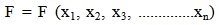 | (1) |
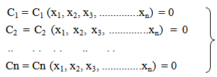 | (2) |
 | (3) |
2. Methodology
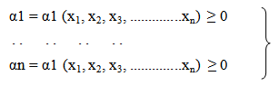
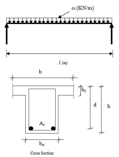
- In order to demonstrate this procedure, a simply supported beam of length l (m), which is part of slab system of a building, loaded with a uniformly distributed load ω KN/m that produced a moment of 150KN.m (Figure 1) is to be designed in accordance to Limit State design principles as specified in [20], so that it is cost effective in terms of reinforcement and cross section area of concrete without exceeding the deflection specified by [20].
 | Figure 1. The beam configuration |
 | (4) |
 | (5) |
 | (6) |
 | (7) |
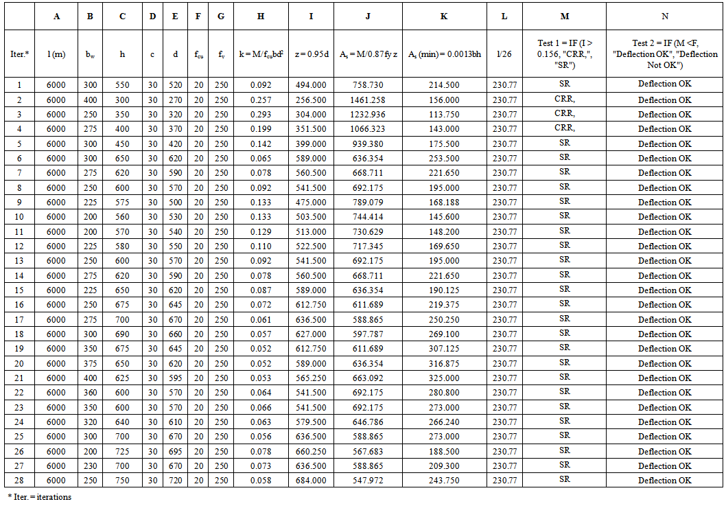 | Table 1. Results of Structural Optimization of A Beam Using MS Excel |
3. Results and Discussion
- The results of the numerical process to find the most economic design subject to acceptable deflection and non-provision of compression reinforcement, using MS Excel are presented in Table 1. Twenty eight iterations were made. From the Table, it can be observed that all the combinations of “h” and “bw” if used will result in design that satisfies the deflection requirement of [15]. The other constraint is that the design must be such that the steel yields before the crushing of reinforcement. That is, the beam must be singly-reinforced, without compression reinforcement. Iterations 2 to 4 did not meet this requirement. But all others met it. Having identified the designs that satisfy the constraints of deflection and no compression reinforcement, the design with the least area of tensile reinforcement among them may be considered as the most cost-effective of the design. From the perspective of cost of reinforcement, consideration may be given to iterations where the areas of reinforcement are between 500 and 600 mm2. Iterations 17, 18, 25 – 28 fall within this category. The final choice may be influence by other factors such as constructional convenience, but at least, the designer can form a reliable picture of how to eventually configure his/her design for cost effectiveness.
4. Conclusions
- From the result presented, it can be seen that an optimal design of structural element with MS Excel can be carried out easily following the approach adopted. Although a simple beam is used here to demonstrate how a designer can optimized his/her design using what is available, without so much stress. The same principle can be used for a more complex structural member or structure, since a structure is formed by putting together small elements. The procedure also has the added advantage of reuse for subsequent designs just by making minor or no modifications.