-
Paper Information
- Paper Submission
-
Journal Information
- About This Journal
- Editorial Board
- Current Issue
- Archive
- Author Guidelines
- Contact Us
Journal of Civil Engineering Research
p-ISSN: 2163-2316 e-ISSN: 2163-2340
2013; 3(5): 148-161
doi:10.5923/j.jce.20130305.02
The State of the Art Report on Arching Effect
 Abstract
 Reference
 Full-Text PDF
 Full-text HTML
Gholam Moradi, Alireza Abbasnejad
Department of Geotechnical Engineering, University of Tabriz, Tabriz, Iran
Correspondence to: Alireza Abbasnejad, Department of Geotechnical Engineering, University of Tabriz, Tabriz, Iran.
| Email: |  |
Copyright © 2012 Scientific & Academic Publishing. All Rights Reserved.
Arching effect is one of the most universal phenomena encountered in soils both in the field and in the laboratory. The arching phenomenon is known to engineers as the reduction of stresses experienced by yielding underground structure. Arching plays an important role in structure interactions such as excavation, retaining structures, pile group effects, tunnel boring machines, culverts and various underground facilities. Arching effect can also be found in the natural landscape. For example, the arching phenomenon in karst terrain can be observed easily and widely. This literature study reviews past researches related to the arching effect and attempts to sort the available information for future research use. The following five categories are covered in this study: (1) Relevance and Application of Arching in Soil Mechanics, (2) Classical arching theories, (3) Analytical approaches, (4) Empirical methods, and (5) Experimental investigations. During this paper the techniques researchers used in their studies are discussed and as a final outcome, the proposed new research field on arching effect is presented.
Keywords: Arching effect, Soil, Stress redistribution, Soil-structure interaction
Cite this paper: Gholam Moradi, Alireza Abbasnejad, The State of the Art Report on Arching Effect, Journal of Civil Engineering Research, Vol. 3 No. 5, 2013, pp. 148-161. doi: 10.5923/j.jce.20130305.02.
Article Outline
1. Introduction
- When part of a soil mass yields, while other part adjoining to the yielding part remains stationary, movement between yielding and stationary parts causes shear stress to develop. This shear stress opposes the relative movement of soil masses. Since the shearing resistance tends to keep the yielding mass in its original position, it reduces the pressure on the yielding part and increases it on the adjoining stationary part. Arching can be best described as a transfer of forces between a yielding mass of geomaterial and adjoining stationary members. The shearing resistance tends to keep the yielding mass in its original position resulting in a change in the pressure on both of the yielding part's support and the adjoining part of soil[1]. If the yielding part moves downward, the shear resistance will act upward and reduce the stress at the base of the yielding mass. On the contrary, if the yielding part moves upward, the shear resistance will act downward to impede its movement and causes an increase in stress at the support of the yielding part.Depending upon relative stiffness in the ground mass, arching can either be active or passive. Active arching occurs when the structure is more compressible than the surrounding soil, and the stresses on the structure are less than those on the adjacent ground. In passive arching, the soil is more compressible than the structure. As a result, the soil undergoes large displacements, mobilizing shear stresses which increase the total pressure on the structure while decreasing the pressure in the adjacent ground. If the soil mass and the structure have the same constitutive properties, the stress along a plane will be uniform. The stress along the vertical direction will be linear and increasing with depth (geostatic stresses) as no arching would be presented in this case. This condition is highly unlikely to be found in natural or man-made environments due to the differences in the mechanical properties of geomaterials (like soils or rocks) and structure components (like steel or concrete).
2. Relevance and Application of Arching in Geotechnical Engineering
- The relevance and application of the arching effect in geotechnical engineering can be discussed in two fields: (1) natural terrains and geological structures and (2) man-made structures. Examples of natural geological structures in which arching plays a role are Karst and Sinkholes[2]. Examples for man-made structures are tunnels[1], buried cylinders and pipes (Marston[3], Spangler[4]), sheet pile designs (Rowe[5]), and pile plugging problems (Paikowsky [6]). Karst is a complex composition of landform and subterranean materials formed by the dissolution of soluble rocks, e.g. limestone, dolomite, and gypsum. Karst terrain is quite often mantled with various surface deposits such as weathered debris, terra rosa soils, loess and alluvium. The most obvious concern of karst terrain is the development of high permeability as water travels through and dissolves the material. Unique characteristics concerning karst terrain were outlined by LeGrand[7]: (1) A general scarcity and poor predictability of groundwater supplies, (2) A scarcity of surface streams, (3) Instability of surface streams, (4) Instability of the ground, and (5) Leakage of surface reservoirs.Sowers[8] indicates that the most important problem in residual settlement is "the collapse of domes within the residual soils and the development of a sinkhole accompanied by catastrophic foundation subsidence, often with little warning." The formation of a sinkhole starts with the creation of a dome cavity that propagates upward until the dome can no longer support the increased load. For the most part, sinkholes collapse when the water table is lowered, and the cavern is subject to an increase in effective stress. In other words, the overburden above the cavern increases such that the dome cavern is unable to support the increased load. In almost every man-made structure related to soil mechanic arching effect can be found. At least it can be obviously observed in underground structures such as tunnels, culverts, retaining walls, and drilling piles.
3. Classical Arching Theories
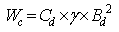
- In 1913, Anson Marston[3] developed a theory to explain the characteristics of a soil column above a buried conduit. Marston found that the load due to the weight of the soil above a buried conduit does not fully act on the conduit; part of the weight is undertaken by the arching action in which load is transferred to the adjacent side material (e.g. soil). Buried conduits can be grouped according to their installation procedures. The two major categories are those installed in a ditch excavated through existing soil, i.e. ditch conduit, and those placed at existing ground level above which an embankment issue sequentially constructed, i.e. projecting conduit. If the top of the structure projects above the ground surface, it is a "positive" projecting conduit; if it is placed in a shallow trench and the top lies below the ground surface, it is a "negative" projecting conduit. Marston assumed that sufficient movement occurs to mobilize shearing resistance on sliding planes. After the movement has been activated, it continues to be effective because of the tendency for movement, even though the actual finite movements have ceased. The above assumption was verified by Spangler and Handy[4] with their in-situ test data. For rigid ditch conduits the following formula is derived by considering the force acting on a thin horizontal slice of backfill material.
 | (1) |
 Where Wc is the load on the conduit, K is the coefficient of the lateral stress, H is the distance from the ground surface to the top of the conduit, μ’=tan
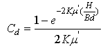
 is the coefficient of friction between fill material and sides of ditch and Bd is the width of ditch at top of conduit. For flexible pipe conduits the value of Wc is given by equation (1) might be multiplied by the ratio Bc/Bd where Bc is the outside width of the conduit.The other assumption that Marston[3] used in his derivations was that cohesion between the backfill material and the sides of the ditch was negligible. This assumption yields the maximum probable load on the conduit and offers a safer estimate for our design purpose.Handy[10] proposed that the shape of the arched soil is catenary and suggested the use of the coefficient by considering an arch of minor principal stress. Kw is derived as:
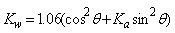 | (2) |
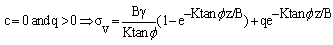
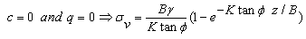
 Russell et al.[10] proposed that K could be conservatively taken as 0.5 more recently. Potts & Zeravkovic[11] proposed that K = 1.0 gave good correspondence with the results of plane strain finite element analyses of arching over a void. This does not seem to be consistent with frictional failure on a vertical plane. However, the assumption of failure on vertical planes is probably an over-simplification, particularly at the bottom of the soil layer near the void.Hewlett & Randolph[12] derived theoretical solutions based on observations from experimental tests of arching in a granular soil. Their analysis attempts to consider actual arches in the soil. The ‘arches of sand’ transmit the majority of the embankment load on to the pile caps, with the subsoil carrying load predominantly from the ‘infill’ material below the arches. The arches are assumed to be semi-circular (in 2D) and of uniform thickness with no overlap. The method also assumes that the pressure acting the subsoil is uniform. Hewlett & Randolph[11] proved that for a 2-dimensional case, the critical point of the arch is always at the crown or at the pile cap. They suggest that the pile spacing should probably not exceed about 3 times the width of the pile caps and not be greater than about half the embankment height. The embankment fill should be chosen such that Kp (Passive lateral earth pressure) is at least 3 (a friction angle of greater than 30°). In addition, in order to make optimum use of the piles, the spacing (s) should also be chosen such that the critical condition occurs at pile cap level, rather than at the crown of the arch.In Terzaghi's experiment, a trap door, which was mounted flush with the base of a box containing sand, was translated downward while the total load on the trapdoor and its displacement were monitored. Horizontal and vertical stresses at various heights above the door were indirectly measured using the friction tape method. Terzaghi noted that arching does not necessitate the crushing of soil particles to support the arch formation. It is a temporary circumstance dependent on the shear stresses in the soil. Terzaghi proposed a theoretical approach for the arching problems in sand under plane strain condition[1]. He defined the arching effect as the pressure transfer between a yielding mass of soil and adjoining stationary parts. The relative movement in the soil is opposed by a shearing resistance within the contact zone of the yielding and stationary masses. Hence, the pressure transfer is possible through the shearing resistance which plays an important role in the arching theory.The equations that Terzaghi proposed for stress due to arching effect are[1]:
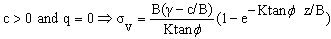 | (3) |
 | (4) |
 | (5) |
 | (6) |
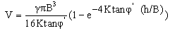
 is coefficient of friction between the granular material and the silo's walls, K is the coefficient of lateral stress and γ is the density of the soil.The arching effect decreases the force exerted on the base of the silosince all the shear stress between the sidewall of the silo and the granular material in the silo are upward. It was also assumed that the vertical normal pressure was uniformly distributed. But according to the experimental performed by later researches, this assumption was incorrect. Hence Jakobson[13] proposed a new method to find out silo pressure. He assumed that every point of the contained mass settles vertically when the load increases which means that the ratio between the horizontal normal pressure and the vertical pressure at every point is equal to the coefficient of earth pressure at rest. So, uniform vertical normal pressure distribution is unnecessary. He proposed the following equation:
 | (7) |
 | (8) |
4. Analytical Approaches
4.1. Continuum Approaches Using Elasticity Theory
- In the following, several analytical solutions will be discussed. First are the continuum approaches which use the elasticity and the plasticity theory to study the stress redistribution in the trap door experiment and arching in underground construction. Second, several discontinuum methods will be illustrated for comparison with the continuum methods.Finn[28] presented closed form solutions for the change in vertical stress resulting from translation or rotation of a trap door. Finn restricted his analysis to problems where displacement of the soil was very small and entirely elastic. The results obtained by the theory of elasticity from Finn were checked against available published experimental and field results. Finn also applied his solution based on elasticity theory to the analysis of retaining walls. The pressure on the wall due to this displacement, however, will only be the pressure on one half of the trap door because the displacement is modified by the effect of removing the stresses on the line corresponding to the free surface of backfill. Chelapati[29] presented a study using Finn's model but dealt with the stresses in a soil field of finite depth. The soil mass was again assumed to be a homogeneous, elastic and isotropic medium but subjected to high overburden pressure. Bjerrum, Frimann Clausen, and Duncan[30] believed that Chelapati's elastic solution can be further extended to give approximate values for the change in vertical pressure at the center of a flexible section located within a rigid horizontal boundary. This kind of approach was taken one step further by Burghignoli[31] when investigating stress redistribution around rectangular underground openings with flexible roofs (crowns). In his analysis, he assumed linear elastic behavior both for the soil and for the roof. Using the arching model from Bjerrumet et al.[30], Burghignoli treated the tunnel crown as a flexible part in a rigid base.
4.2. Continuum Approaches Using Plasticity Theory
- Peck[32] doubted the applicability of arching analyses could be assumed elastic. He stated "The ground movements associated with construction, particularly in soft soil, are so large that the soil is likely to be stressed far beyond the limits of elasticity". Evans[33] also mentioned the inappropriateness of the elasticity assumption. He believed this assumption would result in predicted thrusts and moments larger than those actually measured in field and laboratory installations. Since the elasticity theory cannot describe the arching behavior well, Evans provided an approach which used plasticity theory to solve the problem of a translating trap door within a granular soil. Evans utilized the Coulomb failure criterion and the associated- flow-rule in his development of plastic solutions for the trap door problem. In the plastic solutions of Evans, two major factors govern the deformation of a soil body with a trap door at the bottom. The first factor is the direction of the trap door movement. If the trap door moves downward away from the soil body, then this is the active case. If the trap door moves upward into the soil body, then this is the passive case.The other factor is the variable called the "angle of dilation (v)". The angle of dilation is the angle of the plastic potential with respect to the horizontal. The "plastic potential" is a curve defined as being perpendicular to all plastic strain increment vectors.
4.3. Discontinuum Approaches
- The ideal approach to arching in granular soil is to solve the equilibrium of individual soil particles. This kind of method is called the discontinuum approach. Trollope[34] derived a solution for arching beneath a triangular embankment on a flexible base by this kind of approach. He believed that the stress distribution induced by body-force within granular masses could be evaluated from an analysis of the static equilibrium of a systematically packed system of mono-sized, smooth, rigid spheres. Trollope postulated a "systematic arching theory" in two dimensions. In this theory, soil was represented by single sized discs in a regular packing and each particle was acted upon by six normal forces from adjacent particles. The whole soil body was then solved as a static equilibrium system with the assumptions that horizontal forces were zero and no tensile forces existed. The results from Trollope's solution showed close agreement with the measured values in his experiment of the laboratory scale and full size embankments. Butterfield[35] utilized Trollope's concept in his studies on the stresses developed within silos. He produced results which were similar to those from the silo theory. Maeda et al.[36] utilized the discontinuum approach to study the deformationand failure mechanism in granular materials. They used a micro-structure composed of granular particles aligned as an ellipse as a basic unit. When they modeled the elliptic micro-structure, the shape, size, and number of constituent particles were not taken into account; only the shape of the elliptic structure was considered as an essential parameter controlling the mechanical properties of the structure.
4.4. Numerical Methods
- Due to the simplified assumptions, the aforementioned theoretical approaches are usually limited in the application of practical engineering. Compared to the theoretical approaches, numerical methods are more flexible, and may be the most comprehensive methods available for the analysis of stress redistribution when dealing with arching problems. Several kinds of numerical methods were used by engineers and researchers, including: Finite Difference Method (FDM), Finite Element Method (FEM), Boundary Element Method (BEM), and Distinct Element Method (DEM; also called "Discrete ElementMethod"). Getzler et al.[37] performed a finite difference analysis of plane strain trapdoor problem. The soil was assumed to be linear elastic and Chelapati's theoretical solution was used as the formulation in their analyses. Getzleret al. found the principal compressive stress trajectories produced by the differential settling indicate that a soil arch was formed in the overlying soil, abutting on both sides of the structure and transferring part of the load to those zones. These discoveries agree with the theory which interprets the arching effect as a"structure-like" action of the overlying soil, for example, an arch in plane strain[15],[17] and a dome in three dimensional case. Nielson[17] simulated an advancing tunnel in isotropic, homogeneous, and continuous soil. Again, the soil was treated as a linear elastic material. Several cases were run in their analysis using combinations of the following conditions: (1) lined and unlined tunnel, and (2) linear elastic soil, elastic-plastic soil with strength independent of mean stress and angle of friction, and elastic-plastic soil with strength dependent on the aforementioned parameters. They obtained reasonable data from their finite element program and suggested various values for different tunnel designs in their paper. Stone[38] performed non-linear finite element analyses of the trap door tests to help explain his experimental outcomes. He reproduced the characteristics of his physical model tests with numerical analyses which resulted in a correct prediction of an initial soil localization propagating from the edge of the trap door into the overlying soil. The strain distributions simulated numerically were seen to form an arch at small door displacements. However, the discrete nature of the formation of the soil localizations observed in his physical model did not show in the numerical analysis result. Koutsabeloulis and Griffiths[39] considered the soil as a perfectly plastic material and ran a finite element analysis of the trap door problem. The Coulomb failure criterion was used with the non-associate flow rule. The soil body was discretized to fifteen node iso-parametric triangular elements. A new numerical method called "Distinct Element Method" or "Discrete Element Method" considers granular material as a constitution of many individual particles. The distinct element method can give a better description of the discrete characteristic of agranular material due to its special capability of modeling each particle as a separate entity. Sakaguchi and Ozaki[40] used this method to analyze the formation of arches plugging the flow of granular materials. Their analyses were applied when the granular particles were discharging out of a silo due to the gravity. The granular particle was modeled as an elastic disc which size is 10mm in diameter. A concept called "rolling friction" which allowed the effective development of geometrical interference among particles was introduced in their analyses. Chevalier et al.[41] studied load transfer and arching effect using discrete element method and verified with experimental method. They identified the respective role of peak and residual friction angles on the mechanisms. The three dimensional stress adjustment caused by tunneling related to arching development, using FLAC code and finite difference analysis have been done by Chen et al. in 2011[42]. They showed the development of ground arching during tunneling. Thomas and Shiau[43] used FLAC to analyze the active earth pressure problem. The model used was a rigid gravity retaining wall, with Mohr Coulomb soil backfill and a zero thickness interface element between the wall and backfill to model the sliding and separation between the wall and the backfill soil. Active failure of the soil backfill was induced through pushing the rigid wall away from the backfill, resulting in generation of an ultimate failure load. Sadrekarimi et al.[44] used finite element method in Plaxis code, modeling arching effect, and verified the results with experimental data. They obtained the height of the stable dome with progressive plastic points extended during the model in the analysis.Kempton et al.[45] compared two and three dimensional numerical (FLAC) analyses for various piled embankment geometries. In both cases, the SRR (stress reduction ratio) reduced (i.e. the effects of arching increase) as the ratio of the pile cap width to the space of the piles (a/s) and the embankmentheight (H) increase until a point of ‘full arching’ was reached after which the stress reduction ratio is virtually constant. The maximum displacement and tension in the geosynthetic increase with the SRR. The authors stated that the SRR is significantly higher in the 3D analyses than in 2D analyses for any given a/s ratio. Thus, the maximum displacement at the base of the embankment and the tension generated in the geosynthetic were underestimated in the 2D situation. Kempton et al.[45] also compared 2D and 3D FLAC analysis with the BS8006[46] design method. They found that BS8006 overestimated the geosynthetic tension for all geometries in 2D and underestimated the tension in 3D. For a/sbetween 0.2 and 0.6 with H/s(ratio of the embankment height to the pile space)between 0.6 and 1.4, the BS8006 geo-synthetic tensions were approximately 30% lower than the 3D FLAC analysis. For the other geometries the difference was larger. However, if load factors were used in the BS8006 equations, BS8006 would overestimate the tension in the geo-grid by 30% in both cases. Fakher& Jones[47] argued that the bending stiffness of reinforcement should be considered in the design of earth works over ‘super soft’ clay (the water content is higher than its liquid limit, with a very low yieldstress). The analyses were performed using FLAC. Their results showed that higher bending stiffness of reinforcement causes higher the bearing capacity of the soft clay. However, the effect of bending stiffness of reinforcement will not be as important when the underlying clay was not in a super soft state. Han & Gabr[48] performed a numerical study on reinforced piled embankments with subsoil using FLAC. In the numerical model, each single pile was considered as having an ‘effective’ equivalent circle. This allowed them to use an axisymmetric analysis. The legitimacy of this approach has however been questioned [49], since the unit cell is actually square. They proposed that the ‘soil arching ratio’ (equivalent to the SRR) decreases with an increase in the height of embankment fill, an increase in the elastic modulus of the pile material, and a decrease in the tensile stiffness of geosynthetic. This seems reasonable since all these effects would tend to promote arching in the embankment. Like Russell & Pierpoint[49] the authors noted that the maximum tension in the geogrid occurred at the edge of the pile cap. Rowe & Li[50] investigated the time-dependent behavior of embankments constructed over rate-sensitive foundation soils, using the finite element technique (AFENA). The authors stated that when embankments are constructed over rate-sensitive foundation soils at typical construction rates, the visco-plastic behavior (i.e. creep and stress relaxation) of foundation soils after the end of construction can have a significant effect on embankment performance, although this can be mitigated by the use of reinforcement. Their findings showed that the use of reinforcement can significantly reduce creep deformations of the foundation soils. The stiffer the reinforcement, the less the creep deformations that are developed (other things being equal). Russell et al.[10] presented a new design method for reinforced piled embankments based on Terzaghi’s mechanism supported by results from 3D FLAC analyses. The paper also considers the tension acting in geosynthetic reinforcement at the base of the embankment. Naughton& Kempton[51] compared a number of design methods: BS8006[46], Terzaghi[1], Hewlett & Randolph[11], Jenner et al.[24] (the ‘Guido’ method), Russell et al.[10] and Kempfertetal.[52] using predictions of SRR and the tension in the reinforcement. Stewart & Filz[26] compared five existing methods: BS8006[46], Terzaghi[1], Hewlett & Randolph[11], Guido[53] and the Carlsson[54] design methods using SRR values. Like other authors they reported that the SRR decreases (i.e. arching is more effective) with increasing a/s and H/s. However, for a given geometry, the predicted SRR values vary greatly from one method to the next. They reported that the SRR value is more sensitive to variations in the H/s value for the BS8006 method than for any of the other methods. Later, Ellis et al.[55] noted that the SRR tends to zero for this method as H/s approaches a critical value. For many geometries, the Terzaghi[1], Hewlett & Randolph[11] and Carlsson method[54] gave similar values of SRR. As reported by other authors, the Guido method generally gave very low values of SRR compared to the other methods. Stewart & Filz[26] also investigated the impact of the compressibility of the soft clay between the piles on SRR by parametric numerical analyses of a piled embankment using 3D FLAC. They found that as the clay compressibility increases, the SRR approaches to values obtained from the Hewlett & Randolph[11] method and the Carlsson[54] method. The Guido[53] method greatly underestimated the SRR. Stewart & Filz[26] proposed that the compressibility of the ground between the piles has a large impact on the vertical load applied by an embankment to geosynthetic reinforcement in piled embankments. For this reason, they suggested that the compressibility of the ground between the piles should be a factor in the design of piled embankments.Cao et al.[56] presented an analytical method for determining efficacy, which was based on the principle of minimum potential energy. A similar arrangement to the Han & Gabr[47] axisymmetric ‘unit cell’ was used, with springs to model the pile and subsoil response. Their findings showed that the efficacy decreased with increasing pile spacing to embankment height ratio, and increased with increasing pile cap width. They also showed that the shear modulus of the embankment fill only slightly increased the efficacy of arching in the embankment. The usefulness of geotextile reinforcement was questioned since it reduced the differential settlement between the pile cap and subsoil, and therefor reduced the tendency for arching. However, the authors did note that reinforcement does have the beneficial effect of transferring load from the embankment onto the pile caps. The authors claim that overall geotextile stiffness has little influence on efficacy. However, as noted previously Russell & Pierpoint[49] have argued that assumptions of the symmetric axes do not accurately reproduce the arching behavior. Chen et al.[57] and Chen et al.[58] introduced an approximate closed-form solution, which considers soil arching in an embankment, the settlement of the substratum, and the corresponding negative skin friction acting on the piles. The method was compared with FEM analyses (using the package Plaxis), and the results showed reasonable agreement with the two examples considered, including variation of subsoil stiffness. Chen & Yang[59] derived analytical solutions for a reinforced piled embankment involving maximum deformation of the reinforcement and the stress concentration ratio from the subsoil to the piles. They presented their results as the ‘allowable’ embankment height, which increased with pile diameter, the stress concentration ratio and maximum geogrid settlement. However, by the authors own admission the method has a significant drawback since the stress concentration ratio is required as an input to the analysis. He et al.[60] used FEM analysis to model piled embankments which had lime fly ash and EPS (lightweight material with density of 20 kg/m3) as part of the fill material. The authors compared numerical results with several theoretical methods (Terzagh[1]; BS8006[46]; Hewlett & Randolph[11] and Low et al.[61]) using the soil arching efficacy. Naughton et al.[62] presented the historical development of analysis of piled embankments by discussing the developments in understanding of the arching mechanism, and how the geometry of piles and reinforcement strength requirements have changed over the past quarter of a century. The authors suggested that analysis of piled embankments should consider three-dimensional effects, and the support provided by the subsoil should also be considered in design. Finally, they concluded that the design of piled embankments was complex and was not yet fully understood. Potts & Zdravkovic[63] investigated the behavior of a geosynthetic reinforced fill Load Transfer Platform (LTP) over a void, as considered in BS8006[46]. Numerical analyses were conducted using the Imperial College Finite Element Program (ICFEP), also comparing the output with results from 1g physical models of a ‘trapdoor’. The authors considered the effects of void geometry, the properties of the reinforcement and the properties of the fill layer. Two types of void were considered: an infinitely long void (plane strain) and a circular void (axisymmetric). Their findings showed that BS8006 overestimated the tensile force acting in the reinforcement since the effect of arching in the LTP was not considered. They also demonstrated that the shape of the deformed reinforcement was more accurately described by a segment of a circle rather than a parabola (as assumed in BS8006). The paper also comments that BS8006 may be un-conservative for the damage assessments of overlying infrastructure or buildings, since it predicts a wider settlement and hence lower slopes for a given maximum settlement. Taechakumthorn & Rowe[64] provided a study of the combined effects of geosynthetic reinforcement and Prefabricated Vertical Drains on both the short-term and long-term behaviour of embankments on rate-sensitive soil. The analyses were performed using the finite element technique (AFENA). Their results indicated that reinforcement not only improves the stability of the embankment but also minimizes vertical and horizontal deformation in the foundation. Moreover, Pre-fabricated Vertical Drains work together with reinforcement to reduce differential settlement and increase the rate of excess pore water dissipation in the soil. Van Eekelen & Bezuijen[65] analyzed BS8006[46] from the basic starting points, including Marston’s equation for the load on the pile caps, the assumption of no support from the soft subsoil, and assumptions regarding the line load WT on the reinforcement and the associated catenary equation. They concluded that BS8006 has some fundamental drawbacks. For instance the equations are plane strain rather than three-dimensional, vertical equilibrium was not satisfied (as also previously noted by Love & Milligan,[26]), and the embankment soil properties do not have any influence on the predictions. Finally, an adaptation of the equations was presented; addressing some of these points. Clough et al.[66] applied the finite element method to analyze retaining wall behavior using various assumptions regarding the characteristics of the interface between a wall and backfill. Abusharar et al.[67] presented an analytical method for analysis of reinforced piled embankments. This method was based on Low et al.[61]. The main refinements were: inclusion of a uniform surcharge, consideration of square pile caps (rather than considering a plane strain situation), and taking the skin friction mechanism into account (soil geosynthetic interface resistance). They suggested that further studies should be undertaken using full-scale or centrifuge prototypes to investigate the validity of their theoretical model.
5. Empirical Methods
- For the design of underground openings, there are some simplified methods which basically evolve from previous construction experience. Most of these empirical and semi-empirical methods indicate a value of the pressure to be applied to the support system of the underground opening. Bierbiiumer's theory was developed during the construction of the great Alpine tunnels[68]. According to this theory the tunnel is acted upon by the load of rock mass bounded by a parabola of height h = αH in which α is the "reduction coefficient". This approach assumed that upon excavation of the tunnel, the rock material tended to slide down along rupture planes inclined at (45+φ/2). Szechy[68] discussed the Bierbiumer's theory. He mentioned that the correctness of Bierbaumer's theory could not be completely verified in practice. The best results were obtained for openings excavated at great depths in materials displaying high internal friction (shear strength). Balla[69] assumed in his theory that the geomaterial lying above the tunnel would suffer loosening and downward movement as a consequence of tunnel excavation.This downward movement would take place along some kind of sliding surface and consequently the displacement would suffice to mobilize the shear strength of the material. He assumed the sliding surfaces were circular and they would start from the upper corners of a rectangular tunnel. The oldest and most widely known of these theories is that developed by Kommerell, who determined the height of the loading body from the deformations of the supporting structure in the opening[68]. The theory is justified by the consideration that the displacement or deflection of the supporting structure is representative of the displacement in the disturbed mass of geomaterial. Jenck et al.[70] performed small scale 1-g physical plane strain models. The embankment was modelled using a ‘Taylor-Schneebeli analogical material’, which was an assembly of steel rods with diameter of 3, 4 and 5mm. The subsoil was modelled by foam and the piles were modeled by metallic elements, which allow displacement to be readily determined from images. Their findings showed that the total and differential settlement of the embankment reduced with increasing pile cap size, and the efficacy increased with the embankment height. They also proposed that the arching effect was more efficient for greater rod size in comparison to the geometrical dimensions.Britton & Naughton[71] presented a 1:3 laboratory model of a small plan area of a piled embankment to investigate the influence of the‘critical height’ in design. The base of the model essentially consisted of a trapdoor which could be lowered between pile caps set out on a square grid. Their results were compared with current design methods (BS8006 [46]; Kempfert et al.[52]; Russell et al.[10]; Jenner et al.[24]; Hewlett & Randolph[11]; Terzaghi[1]; Horgan & Sarsby[72] and Naughton[73]) using the critical height and the SRR (stress reduction ratio). Their findings showed that for the value of the critical height, the model test results were in close agreement with Naughton’s approach, and within the range given by Horgan&Sarsby. For the SRR, the model test results showed good agreement with Terzaghi and Naughton’s methods. Heitzet al.[74] investigated differences in arching arising from use of a triangular grid of piles in plan, using FEM analyses. They also carried out large scale model tests to examine the stress distributionin the soil above the pile heads, and the effect of cyclic loading (i.e. traffic on highway and railway embankments) on reinforcement. They found that cyclic loading lead to larger settlement and higher strains in the geogrid compared to static loading. Ellis et al.[55] presented results from a series of centrifuge tests examining the performance of unreinforced piled embankments constructed over soft subsoil in terms of stress acting on the subsoil, and differential movement at the surface of the embankment. They compared the centrifuge test results with predictive methods (e.g. BS8006[46]; Terzaghi[1]; Hewlett & Randolph[11]; and ‘German Recommendations’[52]) over a continuous range of embankment heights.
6. Experimental Investigations and Photoelasticity Methods
- The trapdoor experiments from Terzaghi[1] are small scale experiments. The stresses acting on the trap door are fairly small comparing to those stresses in real construction sites. In order to reach stress levels commonly encountered in the field, McNulty[74] applied air pressure at the surface of the sand in a trapdoor experiment which is otherwise similar to Terzaghi's[1] experiment. In McNulty's experiment, a cylindrical soil chamber with a circular trapdoor at its bottom was used. McNulty developed both active and passive arching in his study by measuring the pressure acting on the trap door (PB) as the door displaced upward or downward by an average displacement. In addition, the effects of overburden depth (H), trap door diameter, surface pressure, and different soil properties were also evaluated in his study. Ladanyi and Hoyaux[76] performed an experimental program involving an ideal granular mass overlying a model trap door in plane strain conditions. The geomaterial was simulated by a stack, 40 inches high and 80 inches wide, of aluminum rods supported by a U-shaped rigid steel frame. The rods were 2.5 inches long and had circular cross sections with two different diameters, 1/8 inch and 3/16 inch. They were cut to the required length, sanded in a sand drum and then mixed in equal proportions to form the testing samples. The resulting granular medium had a unit weight γ ≈ 0.079 lb/in3 and a friction angle φ ≈ 290 at the anticipated stress levels. No surface pressure was applied. Hence, the anticipated stress levels in the experiments were very low. The trap door here was a buried structure, 3 inches wide and 2.5 inches long, represented by a rectangular rigid metallic box, which could be moved up or down like a piston inside the big testing box with aluminum rods. In the tests, the pressure on the trap door was measured as a function of the vertical door movement. The rod displacement trajectories were photographically recorded. A theoretical approach used to estimate the pressure reduction on the trap door was derived by Ladanyi and Hoyaux. However, the major purpose of Ladanyi and Hoyaux was to examine the appropriateness of the assumption of two limiting vertical failure planes in the traditional arching analysis[1]. Harris[77] performed sandbox trap door experiments aimed at stimulating the stress redistribution around a long wall coal mining operation. It consisted of a series of trap doors which could be lowered independently to model the advancing face. Diaphragm pressure cells were located to measure the stresses on the trap doors. By lowering the doors in succession, Harris obtained the stress distribution from beyond the influence zone ahead of the face. Harris' results can also be interpreted as the stress distribution around an advancing tunnel face in soft ground. Ono & Yamada[78] studied the arching effect in the soil mass around a tunnel and behind a retaining wall using rubber membrane filled with air under presser equal to that applied from soil, then the pressure decreased until the air was extracted. The results then compared with that obtained from theoretical study assuming equilibrium of an arbitrary soil element. When a model is constructed smaller in size than the prototype but uses the same material as the prototype, the model is proportionately lighter than the prototype. This isusually not a major problem in models where the dead weight of the system can either be ignored or simply included in the external loads, for example, with applications in structural engineering. However, for geotechnical problems, the body-forces can neither be neglected nor replaced with equivalent external forces that will produce the same effects. Therefore, if a geotechnical system is to be modeled physically at a small scale, both the magnitude and the variation of geostatic stresses have to be duplicated in the model[79]. The best way to do this is by using a centrifuge to attain the desired geostatic stresses in the model. Centrifuge modeling was started in the 19th century when a French engineer Phillips[80] suggested that a centrifuge can be used to simulate self-weight stresses in structural beams. Through the years, physical modeling of geotechnical systems with the centrifuge has become very popular. Centrifuge modeling for geotechnical research has been accepted widely in soil engineering. Iglesiaet al.[79] tried to find out whether the centrifuge modeling scheme also applied to jointed rock mass or not. The experimental setup adopted by Iglesiaet al.[79] at MIT involved a jointed rock mass model with a trap door underneath. The trap door design was similar to several former experiments, e.g. Terzaghi[1], McNulty[75], Ladanyi and Hoyaux[76], Evans[33], etc. Different sizes of small-scale models and of trapdoors were used with various levels of pseudo-gravitational acceleration in the centrifugeat which the door was moved down. The primary objective of this research was to investigate the scaling relationships for centrifuge models of jointed media (wood rods and aluminum rods). A series of tests with granular materials (coarse sands and glass beads) was performed first to give an assessment of similitude for the designed system. It is difficult to use traditional stress measurement methods to measure stress distributions around underground structures of complex geometry. However, photo elastic methods can solve this difficulty. Photoelastic methods are useful for measuring stresses and strains. They are based on a phenomenon that occurs when polarized light passes through certain homogeneous materials such as glass. Under straining, a brilliantly colored fringe pattern appears in the material. This colored fringe pattern results from changes in the index of refraction (ratio of the velocity of propagation of light in a vacuum to its velocity in another medium) proportional to the amount of strain in a material in any given direction. In early photoelastic methods, stresses were induced in an elastic material which was subsequently set, freezing the stresses in place. The elastic material was then sliced and analyzed under polarizing filters. Because the material could be used only one time in each test, the cost of conducting a test by photoelastic methods was expensive. The new photoelastic method uses a special technique which can generate fringes in the material when the material is subject to external loads, but will not freeze fringes in the material after the external loads are removed. The fringes generated during the test are recorded by a high speed camera with a polarized filter. This new method allows one to re-use the photo elastic material and is, therefore, more economical. Riley[81] used the new photoelastic method to conduct a series of studies to determine stresses in the free field of a two-dimensional plate and on the boundaries of embedded structural elements in the plate during passage of a stress wave. Two major parts were included in his experiment. First, was the explosive study. The model used was machined from a large sheet of low modulus urethane rubber. A 5/8 inch diameter hole was machined 4 inches from the point of load application along a radial line 300 inches from the centerline of the plate. Riley then compared these dynamic test results with the static solutions. He concluded that static solutions could be used as a first approximation for computing dynamic stress distributions on the boundaries of discontinuities in elastic materials. He suggested that the photoelastic methods were useful in the study of stress distribution around underground structures under static loads and propagating stress waves. The same photoelastic technique was used by Paikowsky et al.[82] to study inter-particle contact forces. In their experiment, particles were modeled two dimensionally as circular or elliptical discs made from photoelastic material. This makes the measurement of contact forces (direction and magnitudes) possible, and allows particle tracking to evaluate their motion (translation and rotation). Riley's photoelastic measurement technique required detailed measurements to determine the stress field in a single plate. His method treated the whole testing system (a plate contains a hole or an inclusion) as one piece. In other words, the plate and the hole (or the inclusion) in the plate constitute a "continuum". However, if the interaction between discrete particles of a granular material (e.g. sand or rock) is desired under different loads, the use of photoelasticity for granular material modeling[82] would be more appropriate than Riley's continuum system. In 2001, he used photoelastic particles in model of granular material developed in order to observe, track and analyze the fundamental mechanism of arching[83]. Getzele et al.[37] used models composed of aluminum blocks with various shapes that were buried in coarse sand and a uniform pressure was applied to the surface of the sand. The blocks were connected to a ring that served as a flexible support for the model and as a gouge for the total vertical force applied to the structure. After the cylinder was buried in the sand, a uniform pressure was applied on the surface of the sand and the normal force acting on each segment was measured by load cells. Hoeg et al.[84] designed a model tunnel with a rigid steel cylinder, split longitudinally into 12 segments. After the cylinder was buried in the sand, a uniform pressure was applied on the surface of the sand and the normal force acting on each segment was measured by load cells. Atkinson et al.[85] examined the behavior of the shallow tunnels in dry sand using a tunnel model, lined with a thin rubber membrane in both laboratory situation under gravity acceleration and centrifuge with 75g acceleration. The tunnel was constructed initially with an inner pressure equal to the overburden weight, which was then reduced in decrements until the tunnel collapsed. Then they compared the experimental results with the upper and lower boundary theory. The results showed that the upper and lower boundary theory has proper accuracy to estimate the loads applied to the lining of the tunnel. Ono and Yamada[78] studied the arching effect in the soil mass around a tunnel and behind a retaining wall using rubber membrane filled with air under presser equal to that applied from soil, then the pressure decreased until the air was extracted. The results then were compared with the ones obtained from theoretical study assuming equilibrium of an arbitrary soil element. Hashash et al.[86] presented a detailed interpretation of the evolution of stresses around a braced excavation in a deep layer of soft clay. The results provided a new insight for explaining the development of lateral earth pressures for braced excavations and give a quantitative illustration of conceptual load transfer mechanisms and soil arching. The boundaries of the arching zones for both single tunneling and parallel tunneling were determined by Leeetal.[87]. Park et al.[87] performed model tests under 1g conditions to simulate tunneling events in unconsolidated ground with various levels of inclined layers. They found that remarkable non-symmetrical distributions of the earth pressure arose when a tunneling event took place in an inclined layer with 60˚ inclination. Stone and Newson et al.[38] presented the results of a series of centrifuge tests designed to investigate the effects of arching on soil-structure interaction. Continuum approaches to describe the stress dip under sand piles can be found in Wittmer et al.[89], Savage[90] and Didwania et al.[91], and a comprehensive review of continuum efforts was presented by Savage[92]. Michalowskiet al.[93] focused on the limit analysis approach and admissible radial stress fields in prismatic sand piles. In 2006 Chua and Bolton[94] investigate the horizontal arching mechanism transfers horizontal earth pressures acting flexible retaining wall panels to stiff neighboring elements via soil shear stresses using centrifuge technic. He carried out 6 tests at 45 gravities where the panel width and the thicknesses around the model basement were varied. Chen et al.[95] performed plane strain 1g laboratory tests to investigate soil arching in piled embankments with or without reinforcement. Two water bags were used to model the subsoil, and water was permitted to flow out gradually mimicking the consolidation of the foundation subsoil. Their model results showed that stress concentration ratio and settlement are influenced significantly by the embankment height, the ratio of the capping beam width to clear spacing and reinforcement tensile strength. The author’s findings showed that the stress concentration ratio increased with embankment height. A minimum embankment height of 1.6s (where s is the clear spacing between capping beams) was suggested necessary to ensure uniform settlement at the embankment surface. They also stated that the use of reinforcement to improve the stress concentration ratio was more effective as the embankment height increased. Sadrekarimi and Abbasnejad[96],[96] use an instrumented apparatus that comprises concentric circular trapdoors with different diameters that can yield downward while stresses and deformations are recorded simultaneously. They also compared the result with Terzaghi’s theory and upper boundary solution suggested by Atkinson and Pots. They also introduced an equation for stable arch obtained from the experiment.
7. Conclusions
- The arching effect can be defined as follows: "If a portion of an otherwise rigid support of a geomaterial mass yields, the adjoining soil moves with respect to the remainder of the soil mass. This movement is resisted by shearing stresses which reduce the pressure on the yielding portion of the support while increasing the pressure on the adjacent rigid portions." Arching can also occur when one portion of a yielding support moves more than adjoining parts. Generally speaking, arching is stress redistribution occurring in a geomaterial mass.The first systematic study of the arching mechanism was performed by Terzaghi using the trap door tests. Based on these tests, Terzaghi proposed his arching theory in 1943 where he defined arching as "the transfer of pressure from a yielding mass of soil onto adjoining stationary parts[1].Various researchers have performed the trap door tests following Terzaghi[1], modifying the original trap door tests for different purposes. They have used kinds of methods like photoelastic materials to obtain data from the phenomena, but other technics like instrumentation of the soil mass and using new methods to measure the stress and strain in the soil mass during the arching effect could be done. Also in the numerical investigation, there is a lack in the simulation of the arching effect with respect to the large strains, flow, hardening and softening specially in the granular material.