-
Paper Information
- Paper Submission
-
Journal Information
- About This Journal
- Editorial Board
- Current Issue
- Archive
- Author Guidelines
- Contact Us
Journal of Civil Engineering Research
p-ISSN: 2163-2316 e-ISSN: 2163-2340
2013; 3(4): 135-142
doi:10.5923/j.jce.20130304.02
Effect of Base Isolation on the Response of Reinforced Concrete Building
 Abstract
 Reference
 Full-Text PDF
 Full-text HTML
Chandak N. R.
Department of Civil Engineering, Galgotias College of Engineering & Technology, Greater Noida, Uttar Pradesh-201 306, India
Correspondence to: Chandak N. R., Department of Civil Engineering, Galgotias College of Engineering & Technology, Greater Noida, Uttar Pradesh-201 306, India.
| Email: |  |
Copyright © 2012 Scientific & Academic Publishing. All Rights Reserved.
The main aim of using seismic base isolation tool is to reduce the inertia forces introduced in the structure due to earthquake by shifting the fundamental period of the structure out of dangerous resonance range and concentration of the deformation demand at the isolation system. In the paper a parametric study on Reinforced Concrete (RC) building with fixed and isolated base with rubber bearing (RB) and friction isolator (FI) are carried out using response spectrum method. Here, the design spectra recommended by Indian Standard Code IS 1893-2002 (part-I) and Euro Code 8 are considered for comparison. The main objective of this study is to investigate the differences caused by the use of different codes in the dynamic analysis of multistoried RC building along with fixed and isolated base condition. Two different floor plans that are symmetric (SB) and unsymmetric (UB) with torsional irregularity are taken as sample building. To evaluate the seismic response of the buildings, elastic analysis is performed using the computer program SAP2000. It is observed from the comparative study that the building response with isolated base is very less to that of building with fixed base in all the cases and IS code depict higher values in all the cases with and without isolation, when compared to that of Euro code.
Keywords: Base Isolation, Response Spectrum Analysis, RC Building, Elastic Analysis
Cite this paper: Chandak N. R., Effect of Base Isolation on the Response of Reinforced Concrete Building, Journal of Civil Engineering Research, Vol. 3 No. 4, 2013, pp. 135-142. doi: 10.5923/j.jce.20130304.02.
Article Outline
1. Introduction
- Engineers and architects have been carrying out studies for over one hundred years to find applicable methods to reduce the response given to the ground motions by the structures. Seismic isolation and energy dissipating systems are some of the design strategies applied to increase the earthquake resistance of the structures. In simple words, seismic isolation is a process to decrease the response shown to the impacts such as earthquake by separating the superstructure from the ground. In this way, the period and the damping ratio of the structure isolated from the ground are increased. This, in turn, reduces the earthquake forces on the structure. The increase in damping ratio is a natural characteristic for most isolators. This system dissipates part of the energy created on the structure by the earthquake effect, and thus increases the seismic performance of the structure and of its contents. In recent years this relatively new technology has emerged as a practical and economic alternative to conventional seismic strengthening. This concept has received increasing academic and professional attention and is being applied to a wide range of civil engineering structures. To date there are several hundred buildings in Japan, New Zealand, United States, and India which use seismic isolation principles and technology for their seismic design. It may come as a surprise that the rubber foundation elements can actually help to minimize earthquake damage to buildings, considering the tremendous forces these buildings must endure in a major quake[1];[2]. Contrasting the conventional design approach based on an increased resistance (strengthening) of the structures, the seismic isolation concept is aimed at a significant reduction of dynamic loads induced by the earthquake at the base of the structures themselves[3],[4]. Invention of lead rubber bearing (LRB) and high damping rubber bearing (HDRB) gives a new dimension to the seismic base isolation design of base isolated structure[5].[6],[7],[8] covered experimental tests, analytical model and nonlinear dynamic behavior of HDRB.[9] presented a parametric study on reinforced concrete (RC) building using response spectrum method. He considered the design spectra recommended by Indian Standard Code IS 1893-2002 (part I), Uniform Building Code, and Euro Code-8 for comparison. He observed from the comparative study that the response of building using IS code is higher in all the cases, when compared to that of with other codes.[10] presented seismic analysis of fixed base and base isolated building. They concluded that the base isolation helps in reducing the design parameters like base shear, bending moment etc.
1.1. Elastic Response and Design Spectra
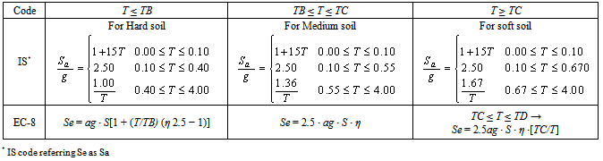
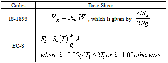
- The earthquake induced ground shaking is generally represented in the form of acceleration response spectra or displacement response spectra. Acceleration response spectra in all current seismic codes, the earthquake actions are represented in the form of a spectrum of absolute accel- -eration. But code acceleration spectra tend to be conservative at longer periods with the result that the long-period ordinates of the displacement spectra are unnecessarily high[11]. Figure 1 shows typical shape of elastic design spectra.In this figure, T is natural period of structure, SeA and SeB show the ordinate values at points A and B of the elastic design spectra, TB and TC show the lower and the upper limits of the period of the constant spectral acceleration branch, and TD shows the value defining the beginning of the constant displacement response range of the spectrum.The ordinates of elastic design spectra Se and inelastic design spectra Sd for the reference return period defined by the earthquake codes can be determined using the expressions given in Table 1. Figure 2 and Figure 3 shows the normalized spectra drawn for ground types described in IS code, and EC-8 code respectively.
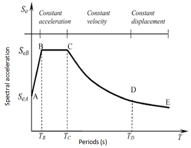 | Figure 1. Typical shape of elastic design spectra |
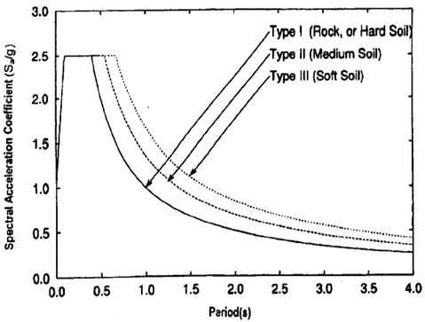 | Figure 2. Response Spectra for 5% damping (IS) |
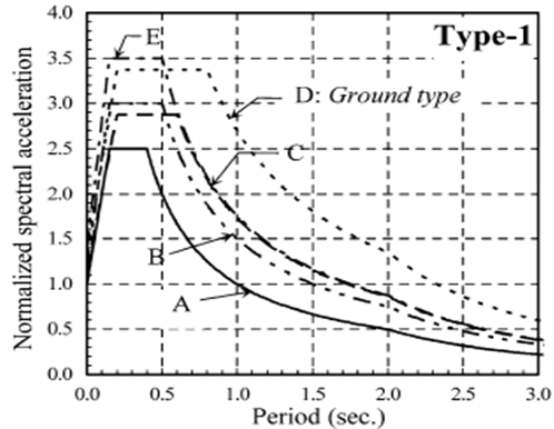 | Figure 3. Elastic design spectra for EC-8 ( is 1.0) is 1.0) |
2. Structural Data
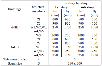
- Sample buildings described herein were selected as typical six story reinforced concrete building. The building has two different floor plans that are symmetric (SB), and unsymmetric (UB). Six buildings are considered and they are henceforth referred to as; 6-SB, 6-UB. The plan dimensions of building, typical at all floors are 22.7m by 13.75 m, with a story height of 3m as shown in Figure 3. The structural system of the building is selected as consisting of structural walls and moment resisting frames in both directions. It is assumed that the structural systems have nominal ductility level. Seismic load reduction factor (R) for special moment resisting frame is taken as 5.
|
 | Figure 4. Floor plan for six story building |
|
3. Modeling of Building and Result Analysis
- To evaluate the seismic response of the building, elastic analyses were performed by the response spectrum method using the computer program SAP2000[12]. The seismic analyses of the buildings are carried out separately in the longitudinal and the transverse directions. However, seismic responses only for x-direction are comparatively presented with graphs and tables in this paper for the sake of brevity. Floor plan of six story building is shown in Figure 4. An aerial perspective of structure is shown in Figure 5. Degrees of freedom at the base nodes are fixed for fixed base case and for base isolation, the seismic isolators in the system are defined as Nl-link components 0.5m in length placed between the fixed base and the columns as shown in Figure 6. The parameters selected to define the utilized rubber isolators[13] in the SAP2000 program are as follows: nonlinear link type: Rubber Bearing, U1 linear effective stiffness: 1500000 kN/m, U2 and U3 linear effective stiffness: 800 kN/m, U2 and U3 nonlinear stiffness: 2500 kN/m, U2 and U3 yield strength: 80 kN, U2 and U3 post yield stiffness ratio: 0.1, other nodes are left free. In addition to rubber bearing the building is analyzed with friction pendulum isolator in the system are defined as Nl-link components 0.5m in length placed between the fixed base and the columns. The parameters selected to define the utilized isolators in the program are as follows: Nonlinear link type-friction isolator, U1 linear effective stiffness: 15000000kN/m, U2 and U3 linear effective stiffness: 750kN/m, U2 and U3 nonlinear stiffness: 15000kN/m, U2 and U3 friction coefficient, slow: 0.03, fast: 0.05, U2 and U3 rate parameter: 40, U2 and U3 radius of sliding surface: 2.23. Columns and beams are modeled with frame elements, slabs and structural walls are modeled with shell elements. Slab has been considered as a rigid diaphragm in each story level. The masses of infill walls are also taken into account in the model. In the analysis, Young’s modulus and unit weight of concrete are taken to be 28000MPa and 25kN/m3, respectively. The damping ratio is assumed as 5% in all modes. The reference peak ground acceleration is taken to be 0.4g that is recommended in IS code[14]. Thus, it is assumed that the buildings are sited in high seismicity zone. Seismic analysis of the buildings accounting for the influence of the local ground conditions is carried out with the help of the design spectra for IS and EC-8 code[15].
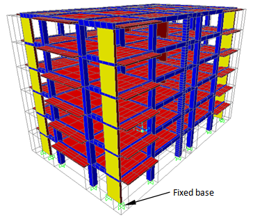 | Figure 5. An aerial perspective of the structure |
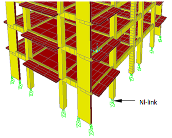 | Figure 6. Nonlinear link element |
3.1. Periods for the Analyzed Building
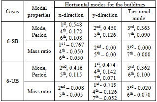
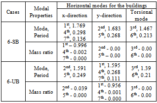
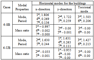
- The mode numbers taken into account for six story buildings are 10. The first seven modes with periods and participating mass ratios for the buildings with fixed base and isolated base are presented in Table 3, Table 4 and Table 5 respectively. For fixed base situation, the fundamental periods are in the range between 0.548 s and 0.071 s. For isolated base with RB situation, the fundamental periods are in the range between 1.769s and 0.111s and in the range between 1.806s and 0.111s with friction isolator (FI). In the first mode the 6-SB, vibrate dominantly in the x direction; whereas 6-UB vibrates in the y direction. The third mode takes place as torsional modes for all the cases considered. The increase in period for structure with isolated base makes sure that the structure being completely removed from the resonance range of the earthquake.
|
|
3.2. Lateral Displacements and Inter-story Drift
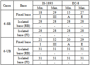
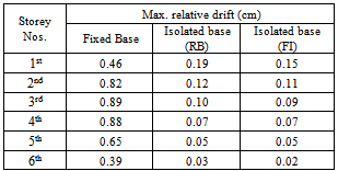
- Minimum and maximum lateral displacements were estimated for all the cases with ground types are given in Table 6. IS code gives maximum and EC-8 gives the minimum lateral displacement values for the buildings with fixed base situation. While lateral displacement is same in all the cases with isolated base situation as the building is separated from the ground. Figure 7 shows relative drift estimated for the 6-story building with fixed base and isolated base with RB and FI in x-direction. As per IS code, the maximum value of story drifts within a story shall not exceed 0.004 times the story height (i.e. 0.004 x 3 = 0.012m). As seen from the Figure 6 the sample buildings taken for study satisfies the condition defined in the IS code. The maximum relative drift is reduced in the range of 58% to 92% and 67% to 95% in ascending order of story for isolated base (RB) and (FI) respectively when compared to that of fixed base situation.
|
|
|
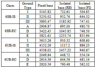
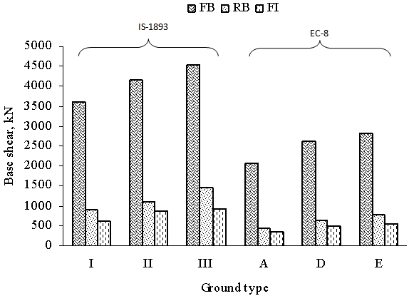
3.3. Base Shear
- Base shear expressions defined in the codes are given in Table 6. The base shear of the building were acquired from seismic analysis using the design spectra corresponding to 5% critical damping considering both fixed base condition and isolated base condition.
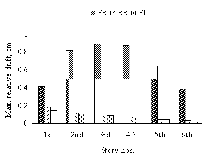 | Figure 7. Maximum relative drift in x-direction |
|
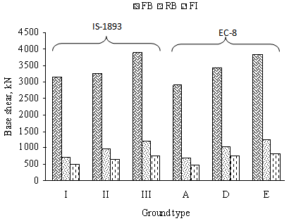 | Figure 8. Base shear for IS & EC-8 for 6SB |
|
3.4. Torsional Response
- IS code gives the maximum torque when compared to that of EC-8 for the both fixed base and isolated base situation for all the ground type. According to IS code, the maximum torque is for ground type III and it is reduced to 26% for 6-SB building and 47% for 6-UB building with isolated base with RB and 30% for 6-SB and 39% for 6-UB for isolated base with FI when compared to that of fixed base situation as shown in Figure 10. Similarly, as per EC-8 code, the maximum toque is observed for D ground type and torque is reduced to 53% for 6-SB building and 54% for 6-UB building with isolated base with RB and 34.5% for 6-SB and 30% for 6-UB building with isolated base with FI when compared to that of fixed base situation as shown in Figure 11.
 | Figure 9. Base shear for IS & EC-8 for 6UB |
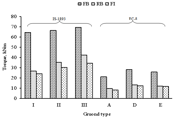 | Figure 10. Torsion for IS & EC-8 for 6 SB |
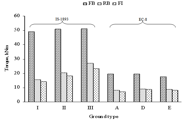 | Figure 11. Torsion for IS & EC-8 for 6 UB |
4. Conclusions
- From the comparative study on reinforced concrete building, the following conclusions are drawn: • The increase in period for structure with isolated base makes sure that the structure being completely removed from the resonance range of the earthquake. • For building with base isolation, the base shear, relative drift and torsion values are adequate due to the higher time period which results in lower acceleration acting on the structures. • Friction pendulum isolators (FI) has reduces further the response of isolated building when compared to that of the response obtained with rubber bearings (RB). • IS code depict the higher values of base shear for similar ground types defined in EC-8 code which may lead to overestimate the overturning moments and could results in heavier structural members in the building. • IS code gives the maximum and EC-8 gives the minimum displacement values for the buildings with fixed base. • In most cases, the estimated drifts for structural components subjected to earthquake force satisfied the drift demand (as per IS Code) for immediate occupancy level, indicating that the structural responses are mainly elastic.
Notations
- Ah-Design horizontal acceleration spectrum value
 - Spectral acceleration coefficient T- Time in sec. R- Response reduction factor Ca, Cv - Soil modified ground motion parameters S - Soil factorη - Damping correction factorW- Seismic weight of building