Moayyad M. Al-Nasra1, Ibrahim A. Duweib2, Abdelqader S. Najmi2
1Department of Engineering Technology, West Virginia University, Institute of Technology, Montgomery, WV 25136, USA
2Department of Civil Engineering, University of Jordan, Amman, Jordan
Correspondence to: Moayyad M. Al-Nasra, Department of Engineering Technology, West Virginia University, Institute of Technology, Montgomery, WV 25136, USA.
| Email: |  |
Copyright © 2012 Scientific & Academic Publishing. All Rights Reserved.
Abstract
Swimmer bars are a new type of shear reinforcement. Swimmer bars can be described as short inclined bars welded to both top and bottom flexural reinforcement. Punching shear takes the form of a truncated pyramid or a truncated cone. A counteract truncated pyramid or a truncated cone of reinforcement formed by swimmer bars will be employed to generate four inclined planes (in the case of truncated pyramid) crossing the four inclined planes of the cracks and a conical surface (for the case of truncated conical shape of failure). The results obtained from plates provided with these plane-crack interceptors, proved the effectiveness of this new system. It is stressed that the stability of the pyramid of reinforcement requires installing larger diameter bars for the swimmer bars at the intersection of the inclined planes. The slope of the swimmer bars may be used to increase their capacities in the vertical direction by increasing the size of the vertical component of the slope. The number of truncated pyramid-crack interceptors may be increased for heavy punching shear forces. The provision of these swimmer bars would eliminate the need of drop panels in flat slabs and raft foundation in the vicinity of columns, leading to savings and ease of construction.
Keywords:
Swimmer Bars, Concrete Slabs, Punching Shear, Deflection, Pyramid Cage
Cite this paper: Moayyad M. Al-Nasra, Ibrahim A. Duweib, Abdelqader S. Najmi, The Use of Pyramid Swimmer Bars as Punching Shear Reinforcement in Reinforced Concrete Flat Slabs, Journal of Civil Engineering Research, Vol. 3 No. 2, 2013, pp. 75-80. doi: 10.5923/j.jce.20130302.02.
1. Introduction
Reinforced concrete slabs are among the most common structural elements. Despite the large number of slabs designed and built, their details for the elastic and plastic behaviour are not always properly implemented satisfactorily. This occurs partially because of the mathematical complexities of the elastic-plastic analysis of these plates, especially for support conditions which realistically approximate those in multi-panel building floor slabs. Reinforced concrete slab floors have taken many forms since their introduction. Some of these were clearly direct imitations of earlier floors made entirely of wood or of wood supported on steel beams. Others were just as clearly invented, with no recognizable ancestors, to suit the properties of the materials, steel bars and concrete[1].Slabs may be divided into two general categories: beamless slabs and slabs supported on beams located at sides of panels. Beamless slabs are described by the generic terms flat plates and flat slabs. The flat plate is an extremely simple structure in concept and construction, consisting of a slab of uniform thickness supported directly on columns. The flat plate is a direct development from the earlier flat slabstructure, which was characterized by the presence of capitals at the top of the columns and usually also by drop panels or thickened areas of the slab surrounding each column. Over the past decades, several structural collapses occurred due to punching shear failure resulting in human casualties and large damages. These collapses revealed some shortcomings in codes of practice and the necessity of reconsidering punching provisions[2]. The investigations of these collapses showed that the collapse initiated from a local punching failure and propagated throughout the structure, in a progressive collapse. The term progressive collapse refers to the spreading of an initial local failure triggered by the loss of one or more load carrying members and leading to partial or total collapse of the structure in a manner analogous to the chain reaction[3].Two types of shear failures have been observed in slabs; “one-way / beam-type” shear failure which involves an inclined crack extending across the entire width of the slab, and “two-way” shear failure, which often governs the slab design, which is also referred to as “punching” shear failure. This failure involves a truncated cone or pyramid-shape surface around the column. In regular concrete slabs, the angle of inclination of the truncated pyramid-shape surface with the slab failure plane typically ranges between 20 and 45 degrees.ACI 318-11 Section 11.11.1.2[4], which requires that, for interior connections of slab-column frames, shear stresses is investigated at a “critical section” located at d/2 from the periphery of the concentrated load. Increasing the slab thickness or using drop panels or column capitals is often not an economical and/or practical option. Increasing slab thickness results in a cost and weight increase, while changes in slab cross section and formwork, when using drop panels or column capitals, take away some of the major advantages of slab-column systems over beam-column frames as uniformity in slab bottom surface and increased clear story heights. Therefore, methods to increase punching shear resistance without modifying the slab thickness is often preferred[3].In 2003, Bin Mu and Christian conducted several tests on concrete slabs including circular specimens with a diameter of 127 mm and thickness of 19 mm were cast[5]. The specimens were supported on a simple ring with a diameter of 101.6 mm and tested under a central patch load. The test setup, testing machine, and loading rate were similar as in the two-way bending tests. The slab specimens were reinforced either with randomly distributed short fibre-reinforced glass or with continuous fibre mesh with equal fibre volume ratios. Many parameters were studied in the test including the effect of fibre type, form and volume ratio in the two bending behaviour and punching shear capacity of the glass concrete slabs. One of the conclusions of the study was that for two-way bending, fibre mesh was very efficient as reinforcement. Short randomly distributed fibres improve the flexural strength and ductility of glass concrete slabs, but do not change their failure modes. Another conclusion of the study was that the fibre mesh position and restrained boundary condition do not significantly influence the shape of the punching shear failure cone.El-Salkawy, Polak and Soudkitested six edge slab column connections strengthened by shear bolts drilled through the slab thickness[6]. The specimens were subjected to vertical load through the column stub and unbalanced moment through two equal opposite horizontal loads applied at the column ends. The slabs were simply supported on stiff supports along the three edges. Steel sections bolted to the supports held the corners of the slab in position. They observed that shear bolts can increase the capacity and ductility of slab column edge connections, and can change the failure mode from punching shear mode to a favourable flexural mode. AL-Nasra and Wang studied the shear strength of concrete on floor slabs[7]. Asha, Al-Nasra, and Najmi investigated the use of swimmer bars in reinforced concrete beams[8]. They showed an improvement in shear strength of reinforced concrete beam by using several swimmer bars.In 2006 Hegger and Sheriftested 17 footing specimens changing several parameters including span to depth ratio (a/d), concrete compressive strength, punching shear reinforcement and the soil-structure interaction[9]. Two series of testing specimens were investigated; the first series were tested by supporting the specimens on column stub and applying a uniform load. Second series were tested on sand. The failure shear cracks seems to be mainly influenced by a/d and not by the concrete strength. The punching shear resistance decreased with increasing a/d and the footings supported on sand showed a higher punching shear resistance than that are uniformly loaded. In 2010 Yang, Yoon and Cook studied the punching shear behaviour of slabs reinforced with high-strength steel reinforcement as shows, and compared the behaviour with that of slabs reinforced with conventional steel reinforcement[10]. The high-strength steel selected for the research conformed to ASTM A1035-07. The influences of the flexural reinforcement ratio, concentrating the reinforcement in the immediate column region, and using steel fibre-reinforced concrete (SFRC) in the slab on the punching shear resistance, post-cracking stiffness, strain distribution, and crack control were investigated. They observed that using high-strength steel reinforcement and SFRC increased the punching shear strength of slabs, and concentrating the top mat of flexural reinforcement showed beneficial effects on post cracking stiffness, strain distribution, and crack control.Behaviour of thick concrete plates that are used for offshore and nuclear containment concrete walls were investigated by Rizk, Marzouk and Hussein[11]. In this research, five thick concrete slabs with a total thickness of 300 mm to 400 mm were tested under concentric punching loading. Four specimens had no shear reinforcement, whereas the remaining one included T-headed shear reinforcement consisting of vertical bars mechanically anchored at the top and bottom by welded anchor plates. The main conclusion was that all specimens without shear reinforcement exhibited brittle shear failures. The addition of T-headed shear reinforcement with a shear reinforcement ratio of approximately 0.68% by volume changed the failure mode to ductile flexural failure. The test results revealed that increasing the total thickness from 350 mm to 400 mm resulted in increased punching capacity and at the same time resulted in a small increase in ductility characteristics.When a reinforced concrete flat slab column structure is subjected to large concentrated load, punching shear cracks occur inside the slab at the column vicinity. They propagate at 20 ~ 50 degree angles through the slab thickness, so that truncated conical or pyramid failure surface around the column forms. Many factors affect the punching shear capacity of flat slab-column connections under static loads. Slab thickness, column dimensions, concrete strength, flexural reinforcing ratio and pattern, and shear reinforcement are all the parameters influencing punching shear capacity. In experiments, the testing methods and conditions, such as the loading rate and scale of specimens, also influence the results, and supporting conditions.Several reinforcement alternatives for increasing punching shear resistance of slab-column connections have been used including; bent-up bars, closed stirrups, shear heads, and shear studs. The main objective of this research is to evaluate the potential of using new style of steel bent-up bars (called swimmer bars) in slab-column connections for increasing their punching shear strength and deformation capacity when subjected to concentrated loads. These swimmer bars will form a shape like a pyramid or a cone around the column in the opposite direction of the failure surfaces. The use of this new concept of shear reinforcement will lead to a uniform slab thickness and the elimination the need for column crown or drop flat plate.
2. Punching Shear Design Requirements in ACI
ACI 318M-11[4]requires that the factored shear force  at the critical section (the perimeter at a distance
  from column face) should be no more than the product of nominal shearforce
  times the shear strength reduction factor which is
  as shown in Eqn. 1.
 | (1) |
The requirement of ACI code for using bent up bars will be considered as follows: a) Shear force ( ) to be resisted by shear reinforcement consists of a single bar or a single group of parallel bar, all bent up at the same distance from the support according to Article 11.4.7.5 of ACI[4].
 | (2) |
But not greater than  Where
Where  is angle between bent-up reinforcement and longitudinal axis of the member,
  is the area of shear reinforcement,
  is the yield strength of reinforcement, and
  is the compressive strength of concrete. b) Where shear reinforcement consists of a series of parallel bent-up bars or groups of parallel bent-up bars at different distances from the support
  shall be computed by Eqn. 3 according to Article 11.4.7.6 of ACI[4].
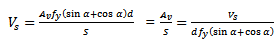 | (3) |
Where S is the spacing between shear reinforcement in mmc) Where more than one type of shear reinforcement is used to reinforce the same portion of a member  shall be computed as the sum of the values computed for the various types of shear reinforcement according to Article 11.4.7.8 of ACI[4].d)
  shall not be taken greater than
  according to Article 11.4.7.9 of ACI[4].e) The factored shear force to be resisted by concrete
  of the critical section without shear reinforcement is also mentioned in Article 11.11.2.1 of ACI[4], as shown in Eqn. 4:
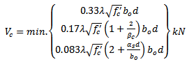 | (4) |
Where  is the ratio of the long side to short side of the column
  is the perimeter length of the critical section. λ= 40, 30, 20 for interior, edge, and corner column, respectively. The nominal shear strength can be expressed according to Article 11.11.2.1 of ACI[4] as follows
 | (5) |
Where  is the nominal shear force in kN
3. Steel Reinforcement
The study covers three specimens, one specimen without swimmer bars and other two specimens with swimmer bars. The first specimen has no swimmer bars (P3), was made by top and bottom of flexural reinforcements with column at the middle of slab, the steel reinforcements of the column was 4Φ12mm. The top flexural steel reinforcement mesh was Φ10 mm and Φ12 mm as shown in Figure 1, and the bottom flexural steel reinforcement mesh was Φ12 mm and Φ16 mm as shows in Figure 2.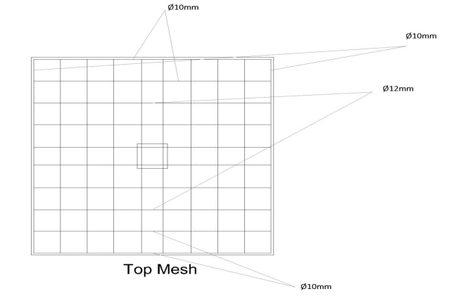 | Figure 1. Top steel reinforcement of the tested samples |
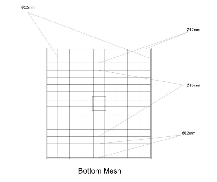 | Figure 2. Bottom steel reinforcement of the tested samples |
The second specimen (PSW12-8) is a flat plate with eight swimmer bars of 12-mm diameter. Four swimmer bars were welded at the intersection of transverse bars and other four bars were welded at the middle distance between of these intersections. Figure 3 shows three-dimensional layout of swimmer bars system (transverse bars and swimmer bars).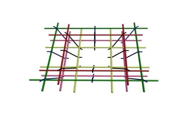 | Figure 3. 3-D model of the swimmer bars layout used in the second and the third samples |
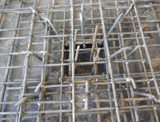 | Figure 4. Reinforcement detail of specimen the third sample -PSW14-8 |
The third specimen (PSW14-8) is flat plate with eight swimmer bars of 14-mm diameter. Four Swimmer bars were welded at the intersection of transverse bars and other four bars were welded at the middle distance between of these intersections as shown in Figure 4.
4. Test Procedure
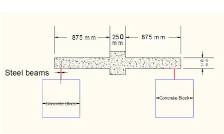
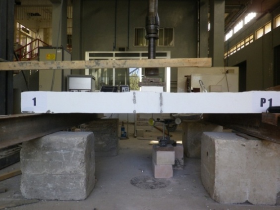
The test started by mounting the square flat plate specimen on two steel beams. Each beam has a cross section composed of two channels back to back. The centrelines of these beams were located 100 mm from the edge of the concrete flat plate, hence the centre- to- centre support distance is 1.8 m. The load was applied on the column that is located at the middle of concrete plate by hydraulic jack. The load was transferred to the specimen by two steel plates of 30 mm thick located underneath the jack’s head. Even though the slab is supported at two opposite sides, the failure of the slab is by punching shear as can be seen in the failure mechanism.Flat plate dimensions are 2.0 m x 2.0 m with 170 mm thickness. There is a stub column that is 250 mm by 250 mm located at the middle of concrete plate as shown in Figure5, and Figure 6. Several concrete cubes were prepared and tested to measure the concrete compressive strength at the time of testing. The mean compressive strength of the five tested cubes is 43.38 MPa, while the mean compressive strength for equivalent cylinder is calculated to be 
 | Figure 5. Specimen setup |
 | Figure 6. Test setup |
Strain and deflection measurements of the specimen were recorded after each load increment, until failure by punching shear. The punching shear tests of all specimens were carried out by using a 730-kN test frame (TONI-MFL).The frame was connected to data acquisition system displaying a record of the load during test.
5. Test Results
The load deflection/deformation were recorded during the testing of specimensP3, loading started at 50 kN, when loading reached 150 kN hair cracks appeared at the side perpendicular to the supports. When increasing the load, cracks appeared and increased in width at the side and bottom face of specimen. Finally, punching shear failure occurred at the load of 407 kN. Similarly data were recorded during the testing of specimensPSW12-8, loading started at 50 kN, when loading reached 150 kN hair cracks appeared at the side perpendicular to the supports. As the load increased, more cracks appeared with gradual increased in width at the sides and bottom face of specimen. Finally, punching shear failure occurred at the load of 534 kN. The last sample PSW14-8 was loaded in the same way. The sample exhibit similar performance in terms of cracks and deformation. The sample eventually failed by punching shear at a load of 660 kN. Figure 7 shows the punching shear strength of the three samples. Figure 8 shows typical punching shear failure of the slab PSW14-8 at the applied load of 660 kN.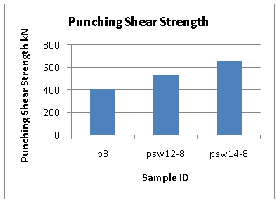 | Figure 7. Punching shear strength of the tested samples |
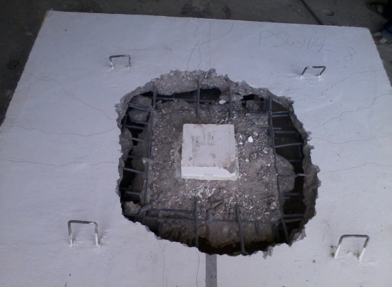 | Figure 8. Failure mode of the 2mx2m PSW14-8 slab at 660 kN central load |
6. Deflection
Two strain gauges were used to measure the deflection at 300 mm from face of column in both direction parallel and perpendicular to the support. These gauges are of 0.01 mm accuracy. The applied load in increased gradually by an increment of 50 kN at which the deflection is measured and plotted as shown in Figure 9. Figure 9 shows a substantial increase in slab rigidity due to the use of the swimmer bars.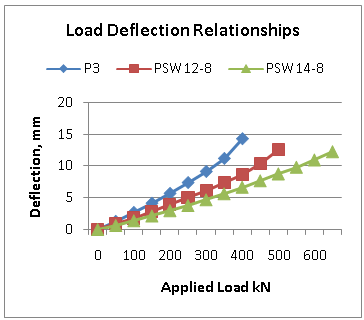 | Figure 9. Load deflection curves for the tested slab samples |
7. Conclusions
The use of the new pyramid form of swimmer bars was successfully used in reinforced concrete slabs. Test results showed that this form of swimmer bars increased the punching shear strength of the tested slabs and improved the deformation capacity of concrete flat plate. The use of swimmer bars as part of the pyramid cage form of punching shear reinforcement can give the designer the ability to reduce the slab thickness and consequently reducing the cost. Also the added punching shear strength by using this type of reinforcement can give the designer options to avoid using drop panels. This type of punching shear reinforcement showed a substantial increase in the slab rigidity by reducing the deflection.
References
| [1] | Robert Park and William L. Gamble, (2000), ″Reinforced Concrete Slabs″ Second Edition, John Wiley & Sons, Inc., ISBN: 978-0-471-34850-4 |
| [2] | Wight, James K. and Macgregor, James G. Mac, (2005), ″Reinforced Concrete Mechanics and Design″ Edition, Pearson Prentice Hall, New Jersey, USA, ISBN-13:978-0132176521. |
| [3] | Arthur H.Nilson, David Darwin, Charles W.Dolan, (2010), ″Design of Concrete Structures″ edition in SI units, McGraw Hill, ISBN-13: 978-0073293493 |
| [4] | ACI, Building Code Requirements for Structural Concrete (ACI 318M-11) - Metric Building Code Requirements for Structural Concrete and Commentary, an ACI Standard and Commentary, 2011.http://www.concrete.org/pubs/newpubs/318M11.htm. |
| [5] | Bin Mu, Christian Meyer, ″Bending and Punching Shear Strength ofFiber-Reinforced Glass Concrete Slabs″. ACI, Vol. 100, No. 2, 2003, pp. 127-132. |
| [6] | Ehab F. El-Salakawy, Maria Anna Polak, Khaled A. Soudik,″New ShearStrengthening Technique for Concrete Slab-Column Connections″. ACI, Vol. 100, No. 3, 2003, pp.297-304. |
| [7] | Al-Nasra, M.M., and Wang, L.R.L., 1994, Parametric Study of Slab-On-Grade Problems: Due to Initial Warping and Point Loads.ACI Structural Journal, Vol. 91 No. 2. Pages 198-210, http://www.concrete.org/PUBS/JOURNALS/OLJDetails.asp?Home=SJ&ID=4596 |
| [8] | Asha, N. , Al-Nasra, M. , Najmi, A. , “Optimizing the Use of Swimmer Bars as Shear Reinforcement in the Reinforced Concrete Beams”, International Journal of Civil and Structural Engineering, Vol. 3, No. 2, November 2012, Pages 313-320, ISSN 0976-4399, DOI: 10.6088/ijcser.201203013030 |
| [9] | Josef Hegger, Alaa G. Sherif, Marcus Ricker, ″Experimental Investigationon Punching Behavior of Reinforced Concrete Footings″. ACI, Vol. 103, No. 4, 2006, pp. 604-613. |
| [10] | Jun-Mo Yang, Young-Soo Yoon, William D. Cook, and Denis Mitchell, “Punching Shear Behavior of Two-Way Slabs Reinforced with High-Strength Steel,” ACI, Vol. 107, No. 4, 2010, pp. 468-475. |
| [11] | E. Rizk, H. Marzouk, A. Hussein, ″Punching Shear of Thick Plates with and without Shear Reinforcement″. ACI, Vol. 108, No. 5, 2011, pp.581-591. |
 Abstract
 Reference
 Full-Text PDF
 Full-text HTML