Xianghe Dai
School of Engineering, Design and Technology, University of Bradford, UK
Correspondence to: Xianghe Dai, School of Engineering, Design and Technology, University of Bradford, UK.
| Email: |  |
Copyright © 2012 Scientific & Academic Publishing. All Rights Reserved.
Abstract
This paper presents the structural behaviour of cold-formed steel cassette wall panels subjected to in-plane shear loads. To understand the influence of configuration, lining material and connector arrangement on the overall shear behaviour of typical cassette wall panels, different lining materials, fastener spacing and positions, edge stiffeners and specific boundary conditions were assumed in the numerical simulations. The comparison and analysis presented in this paper demonstrate typical effect factors to the load-bearing capacity of selected wall panel systems. In particular, the effect of wall opening to the structural shear behaviour of wall panels is highlighted.
Keywords:
Cold-Formed Steel, Cassette Wall Panel, In-Plane Shear Load, Numerical Simulation, Load Capacity
Cite this paper: Xianghe Dai, Structural Behaviour of Cold-formed Steel Cassette Wall Panels Subject to In-plane Shear Load, Journal of Civil Engineering Research, Vol. 3 No. 2, 2013, pp. 65-74. doi: 10.5923/j.jce.20130302.01.
1. Introduction
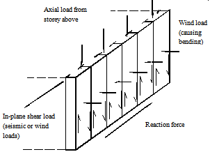
The light gauge (LG) steel cassette wall panel possesses an attractive form of construction for residential and industrial buildings. As a composite structural member, it has been used successfully in a number of projects [1, 2]. LG steel cassette wall panel may be fabricated with various dimensions for different purposes. The dimensions and structural types of a typical cassette wall panel employed for low-rise residential buildings are shown in Figure 1, 3600mm long and 2440mm high without opening or with a door or a window opening.As shown in Figure 2, in engineering practice, the main loads applied to a structural wall system may be vertical compressive load (from the storeys above), horizontal bending load about the minor axis (from wind pressure and suction) and in-plane shear load (from earthquake or wind-induced diaphragm action). As the structural system of a sandwich wall, the LG steel cassette wall panel still attract many designers and researchers. Previous study of such cassette wall panels was mainly focused on the buckling behaviour of individual components under axial loads due to their thin-walled feature. However, the shear behaviour of the overall wall is also very important when the panel system subjected to in-plane shear loads, such as earthquake load and wind-induced diaphragm action. This paper will present the numerical simulation and analysis of typical cold-formed steel cassette wall panels (as shown in Figure 1 and Figure 3) under in-plane shear load.
2. Configuration of Typical LG Steel Cassette Wall Panel System
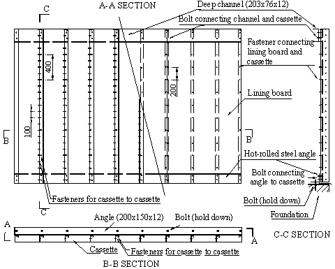
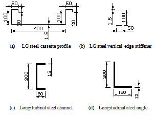
As an illustration, Figure 3 shows the configuration and fixation of a typical LG steel cassette wall panel system. The dimensions of main member cross-sections for the wall panel system, such as cassette profile, edge stiffener, longitudinal channel and angle, are given in Figure 4. The typical cassette wall panel without opening comprises 9 individual cassette profiles (cold-formed steel), 2 longitudinal edge members (1 deep hot-rolled steel channel at the top of the panel system and 1 hot-rolled steel angle at the bottom of the panel system), 2 cold-formed vertical steel edge stiffener members (vertical hot-rolled steel edge stiffener members are alternative options) and 3 pieces of lining-boards (without any lining and with different lining-boards are alternative options). All the components of the cassette wall panel are joined with fasteners (screws). The assembled cassette wall panel is held down to the ground by bolts through the bottom longitudinal angle member and connected to the top floor through its top longitudinal channel member as shown in Figure 3. 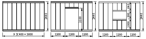 | Figure 1. Dimensions of typical cassette wall panels |
 | Figure 2. Typical loading modes for a load-bearing structural wall system |
 | Figure 3. Structural diagram of the cold-formed steel cassette wall without opening |
 | Figure 4. Cross-section dimensions of constituent member for selected steel cassette wall panel system |
The constituent components for a cassette wall panel system with an opening are similar to those for the above mentioned panel system without opening, but another two vertical edge stiffener members are arranged at both sides of the opening. At the top and bottom of the opening, U-shaped cold formed steel tracks are used (except the bottom of the door opening), which are connected to cassettes by screws directly. Figure 5 shows structural skeletons of typical LG steel cassette wall panel systems (infill materials may be placed between lining boards and cassette profiles for thermal and sound insulation purposes etc.). 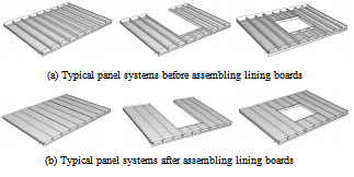 | Figure 5. Skeletons of typical LG steel cassette wall panel systems |
Previous researches [3~8] have indicated that connections are extremely important for shear wall panels. The connectors dominate the in-plane shear stiffness and ultimate load capacity of the wall panel. Figure 6 presents the connection (fastener) locations of various component joining.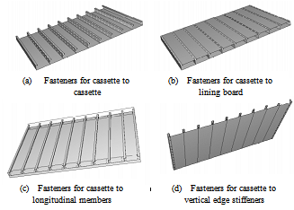 | Figure 6. Connection arrangement of typical cassette wall panel system |
To investigate the influence of connector arrangements (such as fastener strength, spacing and position), component size and material properties on the shear behaviour of the panel systems, the following parameters are considered in this study. Cassette to cassette connections: central spacing of the fasteners connecting web to web (seam fastener spacing), intervals of 100, 200 and 300mm are used. Central spacing of the fasteners connecting narrow flange to narrow flange (extra seam fasteners), intervals of 100, 200, 300mm are employed. The seam fasteners are arranged at the middle of web or at the position 25 mm from either the wide flange or the narrow flange of the cassette profile.Lining boards are fastened to the narrow flanges of the cassette profiles. The fastener spacing interval is 200mm generally and 100 and 300mm intervals are alternatives in the parametric study. In addition, various lining materials (by assuming different deformation moduli including shear modulus) are considered to explore the effect of material properties to the contribution of lining boards.The longitudinal members are connected to the wide flange of steel cassettes with fasteners (screws) as shown in Figure 5. 36 fasteners in 2 rows join the top channel to the cassettes and another 36 fasteners in 2 rows join the bottom angle and the cassettes.For the panel system under horizontal in-plane shear loads, the two bottom corners of the panel will suffer from heavy lift or compression, therefore vertical edge stiffener members were employed to avoid the stress concentration. The C-shaped vertical edge stiffener (cross-section shown in Figure 4), 2440mm long, fastener-spacing 100mm and 200mm are considered in the parametric study. In addition, the bottom end of the vertical edge stiffer member is pinned to the bottom longitudinal angle member. As shown in Figure 3, the wall panel system is held down to the ground through the bottom longitudinal angle. The bolt central spacing is 400mm and in total 10 bolts was used.
3. Finite Element Modelling
FE modelling method has been successful used in the analysis of light gauge steel wall panels [4,7,9]. This section will describe FE modelling method using to capture the structural behaviour of typical LG steel cassette wall panel systems under in-plane monotonic load. The non-linear finite element package ABAQUS software will be employed in the simulation
3.1. Dimension and Material Properties of the Main Components
3.1.1. Cold-formed Steel Cassette Profile
As shown in Figure 4, the thickness of the cold-formed steel cassette profile is 1.5mm (including galvanizing and coating) or net thickness 1.45mm (excluding galvanizing and coating). In the numerical modelling, net thickness 1.45mm is employed. Due to the failure of the overall wall panel is mainly initiated from the failure of connections and by buckling, the plastic property of the cassette steel in numerical analysis is negligible and conventional elastic parameters for steel material are employed, i.e. elastic modulus Es=2.1*105MPa, shear modulus Gs=8.1*104MPa, Poisson’s ratio μs=0.3, mass density ρs=7800kg/m3. The plastic effect of the cassette material is combined into the non-linear properties (load-slip behaviour of fastener) of the connections.
3.1.2. Vertical Edge Stiffener Member
The cold-formed steel vertical edge stiffener is made from the identical cold-formed steel for the cassette profile. Therefore identical net thickness 1.45mm and material properties are adopted in the numerical analysis. To understand the strengthening effect of vertical edge stiffener member to the panel system, hot-rolled steel edge stiffener members with thickness of 12mm are also considered as an option in the parametric study.
3.1.3. Longitudinal Member
Both longitudinal members, including the hot-rolled steel deep channel at the top of the wall and the hot-rolled steel angle at the bottom of the wall are “stronger” comparing with other members. Their cross-section dimensions are presented in Figure 4. In the numerical modelling, conventional elastic parameters are employed, i.e. elastic modulus Es=2.1*105MPa, shear modulus Gs=8.1*104MPa, Poisson’s ratio μs=0.3, mass density ρs=7800kg/m3.
3.1.4. Lining Boards
To explore the effect of lining materials to the overall shear capacity of selected LG steel cassette wall panel systems, four different lining boards by assuming different material properties are used in the numerical analysis. Following Balazs’ research results[10], the material properties of different lining-boards are taken as: plasterboard: elastic modulus Ep=2.0*103MPa, shear modulus Gp=1.0*103MPa, mass density ρp=50kg/m3; chipboard: Ep=5.0*103MPa, Gp=1.4*103MPa, ρp=50kg/m3; plywood: Ep=7.0*103MPa, Gp=9.5*102MPa, ρp=50kg/m3; A special lining is assumed with Ep=2.1*105MPa, Gp=8.1*104MPa, ρp=50kg/m3 to consider the effect of extreme lining boards to the structural behaviour. The thickness of lining-boards is assumed to be 12mm. As well the performance of the lining material is also combined into its connection to steel members.
3.2. Mechanical Characteristics of Connections
Connectors are very important and sensitive components in cassette wall panels. Experimental investigations have proved that the failure of a shear wall panel usually initiates from the failure of connections [10~12]. Therefore selecting appropriate mechanical models of the connection for numerical analysis is especially important. Generally, the mechanical properties of a mechanical connection for members with new material should be determined by test. In this investigation, due to the unavailable of mechanical properties of connections, the determination of mechanical characteristics is based on the previous researches [13~15]. The following connection characteristics are adopted.
3.2.1. Shear Mechanical Characteristics of Connections [14]
For the seam connections (including fasteners joining cassette and cassette, cassette and vertical cold formed steel edge stiffeners), assumed that the slip per seam fastener per unit load to be 0.3mm/kN, or that the initial shear stiffness is 3333N/mm and the failure slip is 5mm. The ultimate (design) strength is determined by , where
  is the net sheet thickness (mm),
  is the nominal diameter of the fastener (mm),
  is the specified ultimate tensile strength of the connected steel sheet (kN/mm2). Taking
  =1.45mm,
  =4.8mm,
  =0.39kN/mm2, then
  =4360N.For cassette to hot-rolled steel member connections, screws with a diameter of 6.3 mm are used. Assuming that the slip per fastener per unit load was 0.15mm/kN, or that the initial shear stiffness is 6667N/mm and the failure slip is 5mm. The ultimate (design) strength is determined from
 , where
  is the net sheet thickness (mm),
  is the nominal diameter of the fastener (mm) and
  is the specified ultimate tensile strength of the connected steel sheet (kN/mm2). Taking
  =1.45mm,
  =6.3mm,
  =0.39kN/mm2, then
  =6770N.For cassette to lining-board connections (fasteners connecting cassettes to lining-boards), assumed that the initial shear stiffness to be 1500N/mm, the failure slip 10mm and the ultimate (design) strength
 =1500N.
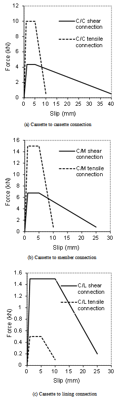 | Figure 7. Force-slip relationships of connectors |
3.2.2. Tensile Mechanical Characteristics of Connections [15]
The ultimate tensile strength can be expressed as:  , where
  is the net sheet thickness (mm),
  is the washer diameter and
  is the design strength of the connected sheet material. For seam connections (including fasteners connecting cassette to cassette and cassette to vertical cold formed steel stiffeners), assume an initial tensile stiffness of 10000N/mm and failure deformation 5mm, taking
  =1.45mm, =16mm,
  =0.39kN/mm2, then
  10000N. For cassette to hot-rolled steel member connections, assume an initial tensile stiffness of 15000N/mm and failure deformation 5mm, taking
  =1.45mm, =25mm,
  =0.39kN/mm2, then
  15500N. For the cassette to lining-board connections, assume an initial tensile stiffness of 500N/mm, failure deformation 5mm and ultimate tensile strength
  500N.
500N.
3.3. Boundary Conditions
According to the configuration and fixation of a typical wall panel system as aforementioned (Figure 3), the bottom angle is pinned to the ground (or rigid base) at 10 points (simulating 10 holding-down bolts, spacing 400mm). The horizontal in-plane load (displacement) is imposed at 10 nodes on the deep steel channel at the top of the wall system. The deep channel and the angle are restrained against the translation movement in the direction out of the plane of the wall. Interactions between cassette and cassette, cassette and member, cassette and lining-board were simulated by contact interaction pairs. “Hard contact” was assumed for the normal contact behaviour as no penetration. A friction factor of 0.4 was adopted for the contact pair in tangential direction in all the FE models.
3.4. Description of the FE Models of Cassette Wall Panels
Because the wall panel comprises of cold-formed steel cassette profiles, fasteners, hot-rolled steel stiffener members and non-metal lining boards, the elements used in the FE models were 4-node shell elements for steel cassette profiles, LG steel vertical edge stiffeners and lining boards, 2-node spring elements for connections and 8-node solid elements for hot-rolled longitudinal stiffener members and hot-rolled vertical edge stiffeners. These elements can reflect appropriately the deformable characteristics of the “thin-wall” members, the non-linear deformation of the connections and the relatively higher rigidity of heavy stiffener members.Shell elements with dimension not exceeding 50x50mm are used for steel cassettes, shell elements with dimension 100x100mm are adopted for the lining boards and solid elements 50x50x12mm for hot-rolled steel members. The dimensions and types of these elements used in the analyses were selected after a mesh size sensitivity study. All the material properties for the components were as introduced in the previous sections.The 2-node spring element with non-linear mechanical property is used to simulate the connections (fastener with the connected members). Each connection is modelled by 3 spring elements, one for tension action and the other two for the shear action. The mechanical properties used have also been introduced in the previous sections. Figure 8 shows the meshes of three typical cassette wall panels via ABAQUS software.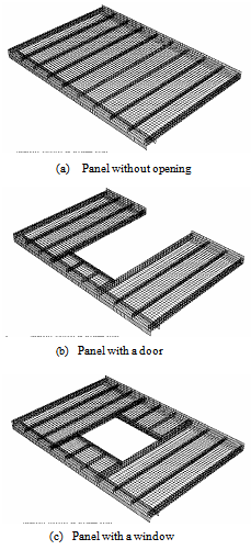 | Figure 8. The meshes of the FE model of cassette wall panels |
4. Validation of Numerical FE Method Against to ECCS Method Prediction
Due to without experimental results available for the selected panel specimens, the finite element method will be validated by comparing the maximum shear capacities predicted by ECCS (1995) [14] and numerical simulation. In design, generally the strength of lining boards just taken as storage, therefore the comparison analysis conducted here is only for the cassette wall panels without opening and without lining board.According to the ECCS (1995) [14], the maximum shear capacity (ignore the buckling) at the ultimate limit state of a steel cassette wall panel without opening and without lining board can be determined by the fasteners in the webs (Pmax) of the cassettes: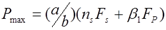 | (1) |
where  : width of cassette wall panel, (3600mm in this research)
 : height of cassette wall panel, (2440mm in this research)
 : design shear capacity of a panel when fastening strength is determining.
 : number of seam fasteners (fasteners in the webs) per seam.
 : design strength of an individual seam fastener.
  : factor to allow for the number of cassette to longitudinal member fasteners per cassette, values are given in the table 5.2 in the ECCS(1995) [14] for case 1 where
 is the number of cassette to longitudinal member fasteners per cassette.
  : design strength of individual cassette to longitudinal member fastener.Comparison of in-plane initial shear strength and stiffnessIn total 6 cases with different seam fasteners were studied. Assuming all panels
  =4360N,
  =4,
=4,  =0.44,
  =6770N,
  =0.254mm4/mm,
  =400mm,
  =1.45mm,
  =210kN/mm2, cold-formed edge stiffeners, edge stiffener pinned to bottom steel angle,
  =2440mm, but different seam fastener spacing intervals: Case-1: seam fastener at web and narrow flange of cassettes, central spacing 200mm,
  =26,
=26,  =200mm,
  =4x10³Case-2: seam fastener at web and narrow flange of cassettes, central spacing 100mm,
  =50,
=50,  =100mm,
  =4x10³.Case-3: seam fastener at web and narrow flange of cassettes, central spacing 300mm, =18,
  =300mm,
  =4x10³.Case-4: seam fastener only at web of cassettes, central spacing 200mm,
  =13,
=13,  =200mm,
  =2x10³.Case-5: seam fastener only at web of cassettes, central spacing 100mm,
  =25,
=25,  =100mm,
  =2x10³.Case-6: seam fastener only at web of cassettes, central spacing 300mm,
  =9,
=9,  =300mm,
  =2x10³.From Table 1, one can find that the maximum shear strengths evaluated by the methods provided in the ECCS (1995) [14] are very close to those obtained from FE modelling. Obviously, the FE method may be used to model the structural behaviour of LG cold formed steel cassette wall panel.
| Table 1. Comparison of numerical analyses and ECCS (1995) for Pmax |
| | ID | Pmax, ECCS(kN) | Pmax, FE(kN) | Pmax, ECCS/Pmax, FE | | Case-1 | 171.6 | 193.3 | 0.89 | | Case-2 | 326.0 | 287.8 | 1.13 | | Case-3 | 120.2 | 134.1 | 0.90 | | Case-4 | 88.0 | 108.6 | 0.81 | | Case-5 | 165.2 | 172.2 | 0.96 | | Case-6 | 62.3 | 77.1 | 0.81 |
|
|
5. Parametric Study
Although a full scale model experiment may provide the most reliable insight into the understanding to the behaviour of structural members, model testing is expensive, time consuming and sometimes limited by the capacity of available equipment. Therefore numerical modelling method is extensively used in parametric study.
5.1. Effect of Connections and Lining Materials to the Cassette Wall Panel Systems
 | Figure 9. Effect of connector spacing, position and lining material to the loading capacity of wall panels with lining boards |
5.1.1. Panel Systems with Lining Boards
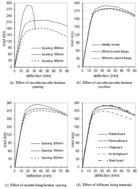
By Figure 9, it can be seen that the cassette to cassette fastener spacing affected the initial shear stiffness and strength of the cassette wall panel systems significantly (Figure 9(a)), but the cassette to cassette fastener position at the web had little influence on the initial shear stiffness but maximum strength. With the fasteners close to the wide cassette flange, the maximum shear capacity increased slightly (Figure 9(b)). The cassette to lining fastener spacing almost had very little influence on the initial shear stiffness of the wall panel, but it changed the ultimate strength of the panels (Figure 9(c)). This is because the connections of cassette to cassette dominated the shear-resistance capacity.The material properties (elastic moduli and shear modulus of the lining-boards) affected the initial in-plane shear stiffness and ultimate strength of the cassette wall panels (Figure 9(d)). However the contribution of lining boards depends on the cassette to lining connections. Normally the connections of the lining boards to cassettes failed before the wall panel reached its ultimate strength and the lining board has not reached its ultimate strength. This is to say, weak lining to cassette connections will restrain the contribution of full lining material strength.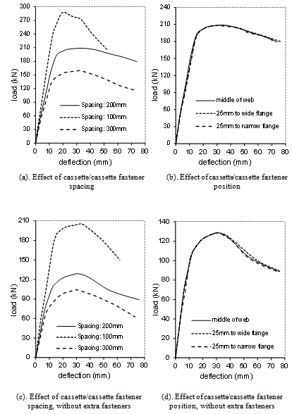 | Figure 10. Effect of connector spacing, position to the loading capacity of wall panels without lining boards |
 | Figure 11. Comparison of cassette wall panel systems with or without opening |
5.1.2. Panel Systems without Lining Boards
As expected, the cassette to cassette fastener spacing presented significant effect to the initial shear stiffness and strength of the cassette wall panel systems (Figure 10(a)). The cassette to cassette fastener position at the web had very little influence on the mechanical characteristics of the cassette wall panel systems (Figure 10(b)).Removing the fasteners connecting the narrow flange to narrow flange of the cassettes (extra seam fasteners), the initial shear stiffness of the wall panel reduced by about 15~30% and the ultimate shear strength reduced by about 25~40% (comparing Figure 10 (c, d) to Figure 10 (a, b)).
5.2. Effect of Opening to the Cassette Wall Panel Systems
Figure 11 presents the relationships of horizontal in-plane shear load to deflection for cassette wall panels with or without opening. One can find:For cassette wall panels with vertical edge stiffeners, it is obvious that the panel without opening had the highest initial in-plane shear stiffness and the wall panel with a door (biggest opening) has the lowest initial shear stiffness. However, the wall with a window opening possessed the highest ultimate strength. This is because the employment of two more vertical edge stiffeners at both sides of the opening increased ultimate in-plane shear capacity. In addition, the initial shear stiffness and strength of panels with hot-rolled vertical edge stiffeners are greater than those of panels with LG steel vertical edge stiffeners.For cassette wall panels without any vertical edge stiffener and any lining (Figure 10 (e)), it is obvious that the panel without an opening had the largest initial in-plane shear stiffness and strength, the panel with a door (biggest opening) had the least initial shear stiffness and strength. This is because the in-plane stiffness and strength of a cassette wall mainly depends on the cassettes and their connections. Furthermore, one can find that the initial stiffness and shear strength of panels without vertical edge stiffeners were much lower than those of the panels with vertical edge stiffeners.
5.3. Comparative Analysis of Cassette Walls with Different Boundary Conditions
To find the effect of members to the shear capacity, a group of boundary conditions were applied to different cases as following. Case-A: Wall panel with plasterboard lining, hot-rolled steel vertical edge stiffeners and other conventional boundary conditions; Case-B: As Case-A, but wall panel without any lining board; Case-C: As Case-A, but wall panel with cold-formed steel vertical edge stiffeners; Case-D: As Case-A, but wall panel with cold-formed steel vertical edge stiffeners and without any lining board; Case-E: As Case-A, but wall panel without any vertical edge stiffeners and without any lining board. Figure 12 shows the horizontal in-plane shear load-deflection relationships of Cases A~E. the following conclusions may be drawn:The lining board increased the initial in-plane shear stiffness very little but it significantly promoted the maximum shear capacity when the wall panel system under in-plane shear load.Vertical edge stiffeners played a very important role for cassette wall panel systems under horizontal in-plane shear load. When the hot-rolled edge stiffeners were replaced by cold-formed edge stiffeners, the initial in-plane shear stiffness and strength of wall panel system reduced significantly. When removed the edge stiffeners, the maximum capacity reduced to half. This is because the vertical edge stiffeners restrained the vertical lift of the wall corner effectively. Meanwhile, the vertical edge stiffeners increased the building capacity at the ends of wall. Cassette wall panels with hot-rolled steel edge stiffeners possessed higher initial in-plane shear stiffness and ultimate strength than cassette wall panels with cold-formed steel edge stiffeners was due to the second moment of area and the connection strength of hot-rolled steel stiffeners are greater than those of cold-formed steel stiffeners.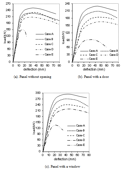 | Figure 12. The effect of boundary conditions on the in-plane shear capacity of wall panel system |
5.4. Description of the Failure Modes
5.4.1. Cassette Wall Panels without Opening but with Lining Board
For cassette wall panels with lining-boards, the failure mode of the wall panel is mainly characterized by the small torsion of the cassette profile, relative slip of the cassette seams, local wrinkling at the lower part of the wide flange and failure of the cassette to cassette, cassette to member and cassette to lining connections. However, for cassette wall panels without vertical edge stiffeners joined to the bottom steel angle, the failure is characterized by the failure of connections of cassette profiles and bottom steel angle, and the crushing wrinkling (buckling) of the wide flange of cassette profiles.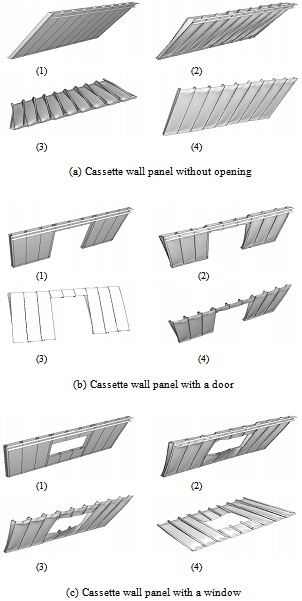 | Figure 13. The deformation of cassette wall panels with or without opening. (1) un-deformed wall panel, (2) deformed wall panel, (3)(4) viewing the deformed cassette in different directions |
5.4.2. Cassette Wall Panels without Opening and Lining Board
For cassette wall panel without lining boards, the failure modes of the wall panel is similar to those of the panels with lining-boards, but the twisting and wrinkling only appear in the cassettes at the both sides of the panel systems.
5.4.3. Cassette Wall Panels with an Opening
For cassette wall panels with an opening, the failure modes were similar to those of panels without opening, but in addition, significant distortion appeared around the opening and a significant flexible bending of vertical edge stiffeners at the sides of the opening.
6. Conclusions
This paper numerically investigated the structural behaviour of cold-formed steel cassette wall panels under in-plane shear loads. According to the comparison and analysis presented in this paper, the following conclusions can be made:There are many factors affect the structural behaviour of cassette wall panel systems, such as connections, lining material and boundary conditions etc. It appears the cassette to cassette fastener (seam connection) at the cassette web dominated the in-plane shear stiffness and ultimate capacity. The panel in-plane shear stiffness and strength decrease with the increasing of the fastener interval spacing although the position of the seam fasteners at web only gives slight influence. The spacing of the lining-board to cassette fasteners had little influence on the in-plane initial shear stiffness but showed visible effect to the maximum strength. The properties of the lining materials have slight effect on the overall shear mechanical behaviour of wall panels. With the increasing of elastic and shear moduli of lining board, the change of in-plane shear stiffness and strength of wall panels are not evident due to the contribution of the lining boards were limited by the lining to cassette connections.For the cassette wall panel without lining-board, the employ of fasteners between the cassette narrow flanges (extra seam fasteners) increased the in-plane shear stiffness and strength of the wall panel, but these additional fasteners did not double the shear capacity of the panel even though the quantity of these fasteners equated to that of seam fasteners in cassette webs.Comparing the structural in-plane shear characteristics of the cassette wall panels with or without opening, it can be found that the wall panel without opening possessed the highest initial in-plane shear stiffness and strength if no vertical edge stiffener adopted. However, for the wall panels with vertical edge stiffeners, the panel with a window opening has the highest shear resistance because of the strengthening effect of vertical edge stiffeners at both sides of the opening.The failure of the cassette wall panel is mainly characterized by the connection failure (here the connect covers the fastener and its vicinity of connected members), small twisting of cassette section and some small wrinkling (local buckling) of wide flange in the area close to the longitudinal members. However, for the cassette wall panel with an opening, the failure of the panel includes a significant distortion of cassette profile around the opening, and the deformation of the vertical edge stiffeners. The comparisons have shown that the FE numerical results for the wall panel without openings and without lining boards have been in good agreement with the semi-theoretical analytical results based on the empirical method provided in the ECCS (1995)[14].
References
| [1] | Davies, J.M. (1998a). “Light gauge steel cassette wall construction”, Nordic Steel Construction conference 98, Bergen, Sept. 14-16, pp 427-440. |
| [2] | Davies, J.M. (2002). “Cassette wall construction: current research and practice”, Int. Conf. On Advances in Steel Structures, Vol.1, 2002, Hong Kong, pp57-68. |
| [3] | Baehre, R. (1987). “Longitudinal shear effect and dimensioning of cassette structures” (translated from: Zur Schubfeldwirkung und –bemessung von Kassettenkonstruktionen), Stahlbau, 9 1987, pp197-202. |
| [4] | Fulop, L. A. (2003). “Contributions to the optimization of structural systems for one family houses with steel structures”. PhD thesis, Politehnica University of Timisoara , Romania, 2003. |
| [5] | Fulop, L. A. and Dubina, D. (2003). “Seismic performance of wall-stud walls”. Meeting of ECCS TC7, Loxembourg, May 2003. |
| [6] | Dubina, D. (2004). “Light gauge steel structures in seismic zones: recent advances and trends”. ICTWS, Jan. 2004. |
| [7] | Fulop, L. A. and Dubina, D. (2004a). “Performance of wall-stud cold-formed shear panels under monotonic and cyclic loading Part 2: Numerical modelling and performance analysis”. Thin-Walled Structures. 2004 (42), pp339-349. |
| [8] | Fulop, L. A. and Dubina, D. (2004b). “Performance of wall-stud cold-formed shear panels under monotonic and cyclic loading Part 1: Experimental research”. Thin-Walled Structures. 2004 (42), pp321-338. |
| [9] | Dai, X. H. (2012). Numerical Modelling and Analysis of Structural Behaviour of Wall-stud Cold-formed Steel Shear Wall Panels under In-plane Monotonic Loads. Journal of Civil Engineering Research 2012 (5). |
| [10] | Balazs, P.(1980). Stressed skin action in composite panels comprising steel sheeting and boards, D40:1980, Swedish Council for Building Research. |
| [11] | Matteis, G. D. (1998). The effect of cladding in steel buildings under seismic actions, PhD thesis, Universita degli Studi di Napoli Federico II, 1998. |
| [12] | Matteis, G. D. and Landolfo, R. (2000). “Modeling of lightweight sandwich shear diaphragms for dynamic analyses”. Journal of Constructional Steel Research 2000-53, pp33-61. |
| [13] | Davies, J.M. and Bryan, E.R. (1982). Manual of Stressed Skin Diaphragm Design. Granda Ltd., London. |
| [14] | ECCS (1995). European Recommendations for the Application of Metal Sheeting Acting as a Diaphragm. Pub.88. European Convention for Construction Steelwork, Brussels. |
| [15] | Rhodes, J. (1991 edited). Design of cold formed steel members, Elsevier applied Science, London,1991. |
 Abstract
 Reference
 Full-Text PDF
 Full-text HTML