Tonye N. Johnarry
Department Of Civil Engineering Rivers State University of Science and Technology, Portharcourt
Correspondence to: Tonye N. Johnarry , Department Of Civil Engineering Rivers State University of Science and Technology, Portharcourt.
| Email: |  |
Copyright © 2012 Scientific & Academic Publishing. All Rights Reserved.
Abstract
The extensive use of plates and frames in construction regularly brings the engineer to confront buckling failure and its analysis and estimates of strength ;this makes it necessary to continue to explore easier ways of finding and verifying buckling solutions. Buckling by the constant initial elastic stiffness matrix is desirable but difficult to find in the literature ;the use of stability functions to modify the stiffness matrices is more readily found. By replacing the curvature in the Euler equation for buckling by its relative value, a successive approximation of steady state relative curvature -deflection ratio is, in-fact, found to be the buckling coefficient. In this way, a new practical buckling criterion is invoked as the resonant relative curvature-deflection ratio . Bars and rigid-frames are examined in this study.
Keywords:
Column Buckling , Bending Moment , Relative Moment(Curvature,Acceleration) , Constant Stiffness Matrix, Deflection, Computer Solution , Buckling Criterion , Resonance
Cite this paper: Tonye N. Johnarry , Buckling by Constant Stiffness and Curvature-Deflection Resonance, Journal of Civil Engineering Research, Vol. 3 No. 1, 2013, pp. 1-15. doi: 10.5923/j.jce.20130301.01.
1. Introduction
The use of a constant initial tangent stiffness in the analysis of buckling of bars and rigid frames is most desirable but is ,as yet, very difficult to find in the literature A constant stiffness method, as it is the case of non-linear finite-element analysis demonstrated by Zienkiewich[1] and further studied by Duncan and Johnarry[2] always promises to be easier than those that rely on tangent-stiffness-changing iterations with load stages. Iterations based on stability functions alteration of the stiffness matrix according to the extent of the axial buckling forces is amply demonstrated by Ping-Chun Wang(1965),[3], Wood(1974),[4] relied on stiffness alteration in his stiffness distribution buckling studies. Georgios Mageirou and Charles Gantes(2006),[5] and Messaoud Bourezane(2012),[6] ,among others, relied on Stability functions-based matrices in their buckling research on beams and frames . For example, in the slope-deflection equation, the familiar rotational beam stiffness, 4EI/L=(k11) will change to (k11) + function(c,E,I,L) ;c=compression. There are several other approximate methods for critical loads which by-pass the use of stability functions; the treatment by Horne,1975,[7] ,which relied on elastic story drifts ,stands out for its simplicity as it requires the elastic solution and the employment of a formula on the solution displacements/rotations ;the formula was not completely proven. In recent studies Johnarry[8,9] has been examining the employment of acceleration-deflection resonance in new alternative solutions for plates and re-definition of buckling criterion .( curvature ≡ acceleration)
2. Analysis
2.1. Resonance as a Buckling Criterion
In the presence of fiction ,the Euler equation will be, | (1) |
For a pin ended bar , tryY = Σ Am Sin m πx/LContinuing , | (2) |
Am →∞ as P → EI(m2) π2 / L2 ;(m=1 for mode-1)Buckling is sudden appearance of uncontrollably large displacement , by this view. Now, in this case(Y,xx)shape = Yshape = Sin m πx/LCan it also be generalized that buckling is a condition of resonance between curvature and displacement ?Can relative-acceleration be substituted for acceleration ? Clearly in this pin-ended case there is no standing support fixing moments and the relative acceleration is everywhere the same as the acceleration. A relative curvature envelop has an immediate common property with its relevant displacement envelop; both have zero end-values if the end values of displacements are prescribed zero. In the event the shapes of the two envelops are similar there is then resonance ,buckling, vibration.
2.2. Relative Acceleration – Displacement Analysis
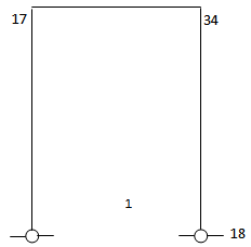
 | Figure 1. Pinned – Clamped Column |
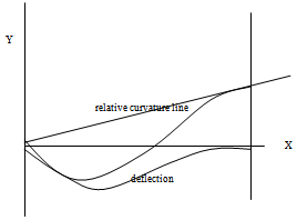
As an example, in Fig.1 ,consider the pinned-fixed column. Chose the Y-function to be able to satisfy all geometric boundary conditions; let,Y = Sin K X +Cos KX + A X + B;( -K2(Cos KX) =0;so,  | (3) |
 | (4) |
Let the relative curvature be , | (5) |
S=0 from starting conditionsAlso, in relative curvature analysis, terminal ends of a line have zero relative curvatures; so,At x=L , (Y,xx)rel .=0 ;so, R=(K2 Sin KL) /LCompare shapes of ‘Y’ and ‘Y,xx-rel-zeroends.’ | (6) |
At X=L, Y=0; so A= - (SinKL)/L ;from Eq.3 (BCA) Y,xx-rel / Y = K2 (-Sin KX + (X/L)Sin KL) / [ N*(Sin KX –  | (7a) |
 | (7b) |
AT X=L; Y,x = 0; so, K CosKL + A =0, and with Eq-7, | (8a) |
and,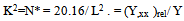 | (8b) |
So far in this section, no buckling force-P, has been mentioned , but from Euler’s buckling relation for a pin-ended bar, | (9a) |
 | (9b) |
 | (9c) |
(Y,xx-rel . / Y)→ resonant , Y,xx-rel /Y >> Y,xx-0/Y ; Y→∞ , at bucklingSo, E I Y,xx-rel = -P Y 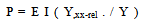 | (9d) |
So, buckling(sudden large displacement) is indicated if relative acceleration and displacement become resonant.Consistent displacements can be introduced and adjusted until the relative curvature - displacement in Eq.9d is constant at each station and when that happens the force ,P, assumes a critical value- Pcr . This is the exact solution for the problem. In a computer stiffness matrix solution no displacement function is called for ; the slope deflection equation matrix formulation provides initial consistent nodal displacements.The point-wise constant relativeacceleration-displacement ratio can also be presented to vibration relation, clearly.
2.2.1. Energy Method Versus New
Acceleration-displacement ratio methodIn the energy method the buckling load is found from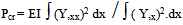 | (10a) |
In the present method it is found from,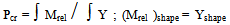 | (10b) |
If (Mrel)curve shape ≠ Ycurve shape , then rationalize,(Mrel) = H Y ; find scalar- H ,so that,∫ (Mrel) Y / ∫ Y.Y = HExamine a pin-ended column by the restricted function , Y= X(1-X)Mfixity =0 ; physical support condition ,so, Mrelative = MMrel = EI (-2) = H . Y∫ EI(-2) Y dx = ∫ H Y. Y dx ; H=10 EIPcr = 10 EI ; exact = (π2 )EIThe energy integral Eq.-10a will give a less approximate result of Pcr=12EI.Eq.-10b is easier than Eq.-10a in many instances.Fig.2 gives an indication of how the fixed-fixed column is to be handled(suitable equation Y=Cos Kx +C) .The pin-pin Column is illustrated in Fig.3 divided into 38-elements and later solved. 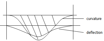 | Figure 2. fixed – fixed column |
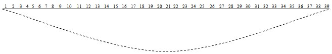 | Figure 3. Pin-Pin Column, 38-elements, 39-nodes |
2.3. Computer Stiffness Solution
The equation Y = J ( Y″ + RX + S ) is solved by successive approximation. | (11) |
The right hand side(rhs) of eq-11 is available from stiffness analysis , point-wise.Start by applying a transverse load (say uniform load of any magnitude)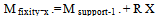 | (12) |
 | (13) |
Interpret the bending moments so found as the next set of applied loads and re-solve.(other acceleration expressions can be tried)A solution is found when ,point-wise,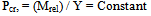 | (14) |
is obtained; the displacement and the relative acceleration curves are then similar or of constant ratiopoint-wise. The basic beam stiffness can be stated as:  | (15a) |
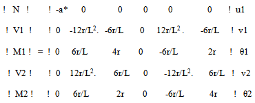 | (15b) |
So, find for (N=axial force,M=moment,V=shear-force;member from point-1 to2); a*=EA/L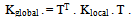 | (15c) |
and conduct routine stiffness analysis . The stiffness matrix once found will remain unaltered in the iterations and produces very fast analysis. The results for the pinned-fixed column, the fixed-fixed column and a portal frame in axial compression against its mirror are presented
2.3.1. Pinned-Fixed Column and Others in Computer Solutions
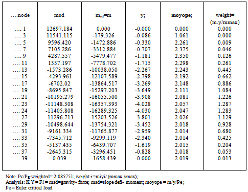
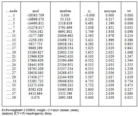
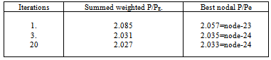
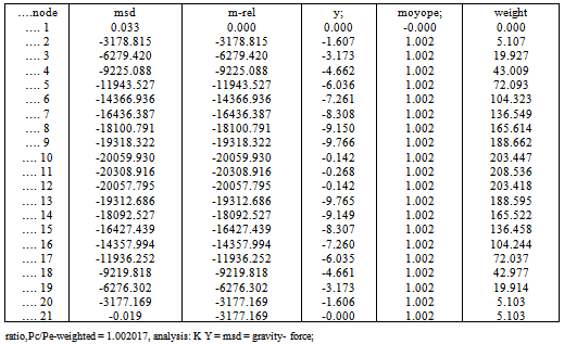
The fixed-pinned column is ,often, a severe test in buckling studies and so the member is divided into 38 equal elements and 39- nodes. The record “moyope” means (mrel)/(y)/PE .;(PE .= reference Euler load)The quotient is deficient in the vicinities of zero deflections and rapidly changing bending moments. Table 1 shows that the predominant ratio of 2.08 at many nodes is virtually exact. Where the ratio is much different from this the station weight measured by (y m/mmax) will be very small. Tables-1,2,3 show results for iterations =1,3,20. Table 4 compares iterations and the quality of results leading to the conclusion that three iterations are sufficient in a given situation.As shown in Table-5 for the pin-pin column(20-elements) the result of 1.002 is ,practically, exact and it must be recalled that the stiffness solution did not assume a sinusoidal Y-variation that, in a manual solution, would have led to the same correct result. The result confirms that a column buckles into a sine-curve .The result of the fixed-fixed column (38-elements) is given in Table-6 and the result P/Pe=4.006 compares with the exact value of 4.0Table 1. fix-pin-col; iteration= 1; bars = 38, nodes=39
 |
| |
|
Table 2. fix-pin –col; iteration= 3, bars = 38
 |
| |
|
Table 3. fix-pin –col; iteration= 20, bars = 38
 |
| |
|
Table 4. fixed-pined column iterations and P/PE .comparison
 |
| |
|
From Table-4 and from experience three iterations are often sufficient.Table 5. pin-pin-col;itertn =3, bars = 20
 |
| |
|
Table 6. fixd-fix- col; itertn 3; bars = 38
 |
| |
|
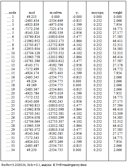
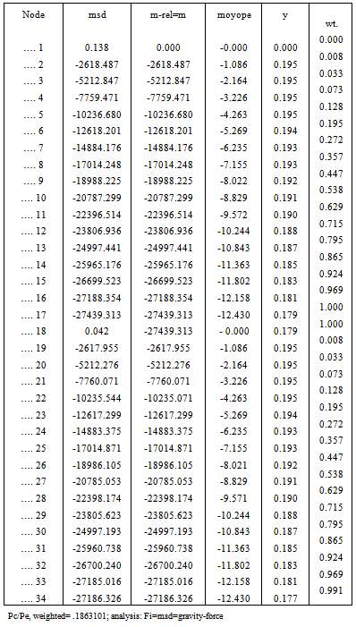
Table 7. fixed-base portal + mirror, itertn =3; bars= 34;(Ibeam)/(Icol)=0.1
 |
| |
|
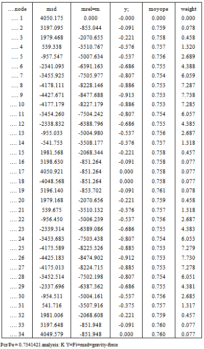
Table 8. fixed-base portal + mirror; itertn =3, bars = 34; Ibeam /(Icol) =1
 |
| |
|
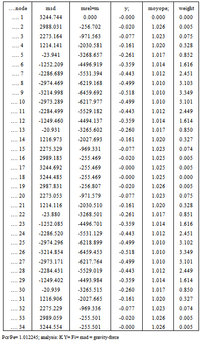
Table 9. fixed-base portal + mirror; itertn =3, bars = 34;(Ibeam)/(Icol)=100
 |
| |
|
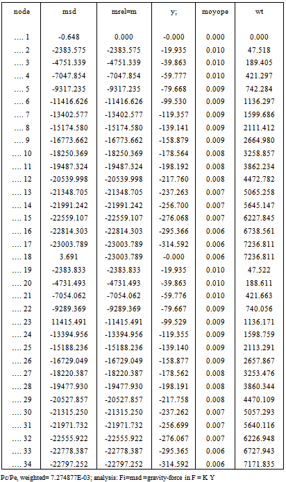
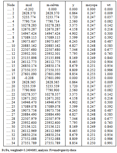
Table 10. pin-base, 1-cell-portl-dirct itrtn= 5; bars = 34; Ib/Ic=0.01
 |
| |
|
Table 11. pin-base, 1-cell-portl-dirct itrtn= 5; bars = 34 ; Ib/Ic = 1
 |
| |
|
Table 12. pin-base, 1-cell-portal-direct itrtn= 20; bars = 34 ; Ib/Ic =100
 |
| |
|
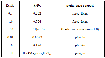
A fixed-base lone portal frame,Fig.4, is analyzed with its mirror so as to find conservative energy situation, as is the case of the cantilever column. The results are as exact as the isolated columns already examined for various beam-to-column stiffness ratios in Tables 7,8,9 and summarized in Table-13.In the case of the pin-pin portal frame,Fig.5 there is no need for the mirror part as the displacement curve is conservative directly. Results are given in Tables,10,11,12 for different I-beam /I-col ratios. The exactness of the results is maintained.Many results of these frames for various I-b/I-c ratios can be easily found as demonstrated . Column strengths and design graphs as found in Wood(1974),[4] and in design Codes,BS-8110,BS-5950[10,11] can be replicated by the present method.; the objective here is to show a very fast buckling solution method without going outside the conventional elastic stiffness analysis that forms the back-bone of bridge and building frames design analyses and studies. Table 13. P./PE. for portal frame for various Ibeam/Icol
 |
| |
|
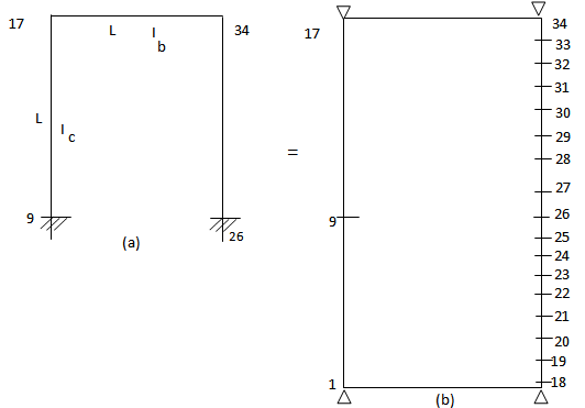 | Figure 4. Fixed-base sway frame; (a) alone (b) plus mirror for analysis; θ9= θ26 = O; nodes 1-9,18-26 = mirror |
 | Figure 5. Pin-base single portal-analysis |
2.4. Extension to Substitute Frames
The substitute frame method allows a large frame to be reduced to easier- to -handle limited frames in the design process.In applying the present method to any story the main issue to contend with is the value of the fixity at the base of the story. It is somewhere between fixed and hinge support. The present method is based on elastic analysis and so super-position of two solutions(partial fixity and partial hinge) is studied.
2.4.1. Column-Base Fixity Ratio ,FR
Beams at joints provide fixity to columns and a fixity ratio is defined asFR = (I/L2)beam / [(I/L2)beam + (I/L2 )col]; maximum=1.0 whenbeam is infinitely rigid (16) So, hinge-support ratio = 1 -FR The equation is rational and highly effective. It is known that in the buckling environment, moments are proportional to (P.y) or (I/L2) and moments must be balanced at joints of beams and columns.
2.4.2. Examples of Story Analysis in Multi-story Frames
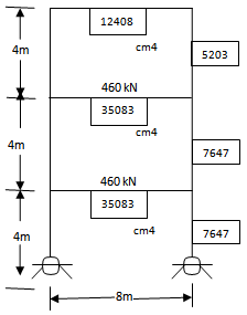
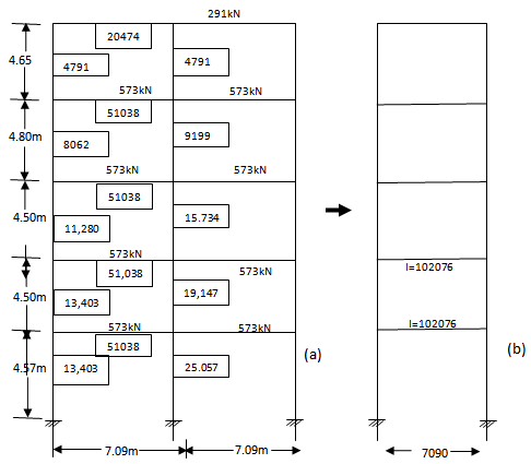
These frames ,Figures 6,7,8,9 were taken out of the paper by Horne[7]; results summarized in Table 14..(Example-Figure.6.)..3-storys frame, Figure. 6; Pinned-bases; try bottom story ;fixity=0; so direct analysis with pinned bases .Enter program with Icol=76470000 , E=201,000, L-col=4000, L-beam=8000 ;Ibeam=350,830,000find Pcr/PE =0.2177; Papplied =1088Kn.; Pcr /Papplied . = 3.79, ((alternate result quoted by Horne[7]=3.78)); ;;try another story if necessary...(Example-Figure.7(same as Fig.6 but fixed feet),)) ; ; try story-2stp1.. FR = (350,830,000/80002) / (350,830,000/80002 +76,470,000/40002) =0.534stp2.. Hinge-factor =1- 0.534 = 0.464stp3.. Pcr-hinge/PE= 0.2177 –already found above .st4..With new fixed-fixed boundary conditions ,find ( Pcr /PE )=0.881st5..So, (Pcr/PE)story = 0.881(0.534)+0.2177(0.466) = 0.572 ; Pcr = 10,828 Kn.st6..(Pcr/Papplied) = 10847/628 =17.24(Example-Fig.7,story-1)..Try bottom story to check if more critical; (Fr = 1; Pcr =16,680; Papplied = 1088.Pcr /papplied = 15.34; compare exact 14.72 - - Table 14;)(Example-Figure.8,botm story.).. 8-story frame shown in Figure.8 ;try bottom storystp1.. FR = (236000000/30502) / (2360000000/30502 + 479160000/50802) = 0.577stp2.. solve with base fixed-fixed ; Pcr/Pe = 0.573stp3.. solve with pinned bases ; Pcr/Pe = 0.136stp4.. ( Pcr /Pe)combined = (0.577(0.573) + 0.423(0.136)) = 0.3875stp5.. Pcr = 0.3875(π2 )E (479160000 (2legs)) /(50802) = 28,547 Knstp6.. Papplied = 7,120 Kn ; Load-factor Pcr/Papplied = 4.0 ((alternate result quoted by Horne[7]=3.95 ))(Example-Figure.9,story-2).. 5-story – 2bay frame ;Figure.9 ; try story-twostp1..first reduce to one bay 5-story frame(i.- add up I-beams ;ii.- add up I-cols and divide by two)stp2.. find FR = 0.6591stp3 solve for fixed bases ; Pcr/Pe = 0.9035stp4.. solve with pinned bases ;Pcr/Pe = 0.223stp5.. (Pcr/Pe)combined = 0.671stp6.. Pcr/Papplied = 7.51 for E=201,000N/sq-mm ((alternate result quoted by Horne[7] =7.70)) (Example-Figure.9,story-1)..try story-one ; FR =1 ; bases actually fixed-fixed ,so pin-pin contribution is none...stp1 ; Pcr/Pe = 0.893..stp2 ; Pcr / Papplied = 8.52 > 7.38 for story-2 found above.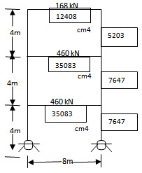 | Figure 6. pin-pin frame |
 | Figure 7. fixed-fixed frame ,same as Fig.6 but fixed |
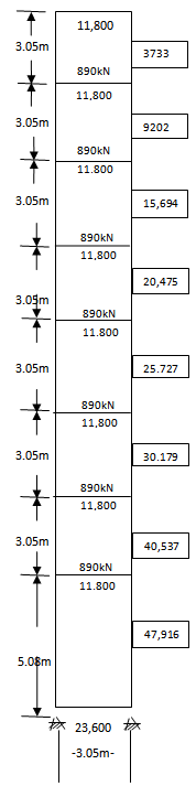 | Figure 8. Frame |
 | Figure 9. Frame |
2.4.3. Quality of Results in Frames
The fixity ratio method of mixed-boundary-conditions studied here led to results within 5-percent of the best of other quoted results in the limited experience of the method for multi-bay multi-story frames.
3. Conclusions
Buckling instability has been successfully defined as the invariant point-wise quotient of the relative-moment and the consistent displacement, easily obtained from an iterative load-displacement analysis using the constant elastic tangent stiffness. Examples in beams and frames were tested in this preliminary study. About three iterative solutions are needed for an analysis. Above the ground story , the upper storys operate in partial fixity(between fully fixed and pinned);partial fixity and partial pinned factors were rationally found to produce a super-posed solution; each solution is purely elastic. The critical load of each story was easily found directly.
ACKNOWLEDGEMENTS
This study has been financed by Rootway Academy Services .
References
| [1] | Zienkiewich, O.C. The finite element methods in engineering science. McGraw-Hill ,London, 1971 |
| [2] | Duncan ,W. and Johnarry, T;1979. Further studies on the constant stiffness method of non-linear analysis of concrete structures; Proc., Instn of Civil Engrs;Part- 2,Vol.67,London,P951-969 . |
| [3] | Ping-Chun Wang ,1965 : Numerical and matrix methods in structural Mechanics ; John Wiley&Sons |
| [4] | R.H.Wood ,1974: Effective lengths of columns in multi-storey buildings. The Structural Engineer.,July 1974,N07,Vol-52 |
| [5] | Georgios E. Mageirou and Charis J. Gantes ,2006 ;Buckling strength of multi-story sway, non-sway and partially- . sway frames with semi-rigid connections.Journal of Constructional-Steel-Research 62,2006,893-905(www.elsevier.com/locate/jcsr) |
| [6] | Messaoud Bourezane ,2012 : Buckling Finite Element Analysis of Beams and Frames; Proc. World Congress on . . .. Engineering ,Vol.1,WCE,2012,July 4-6,London,U.K |
| [7] | M.R.Horne ,1975: An approximate method for calculating the elastic critical Loads of multi-story plane frames;The Structural Engineer,June1975-No.6/Volume 53 |
| [8] | Tonye.Ngoji Johnarry ,2011: Acceleration-displacement ratio transform of differentials for transverse plates and . constant stiffness buckling solution. Innovative System Design and Engineering,ISSN 2222-1727(Paper)ISSN 2222- . 2871(online),Vol.2,N0.4,2011 (www.iiste.org) |
| [9] | Tonye Ngoji Johnarry ,2011 ; A new plate solution by tuned acceleration-displacement ratio transform of differentials. Canadian Journal on science and engineering mathematics;online,Oct,2011 |
| [10] | B.S-8110 ,1987 ; Structural use of concrete, BS-8110 , 1987, British Standards Institution N0-2,Park Street, London . |
| [11] | B.S-5950 ,1985 ;Structural use of steelwork in building ;, BS-5950 ,1985,British Standards Institution ,London. |
 Abstract
 Reference
 Full-Text PDF
 Full-text HTML