-
Paper Information
- Next Paper
- Previous Paper
- Paper Submission
-
Journal Information
- About This Journal
- Editorial Board
- Current Issue
- Archive
- Author Guidelines
- Contact Us
Journal of Civil Engineering Research
p-ISSN: 2163-2316 e-ISSN: 2163-2340
2012; 2(6): 108-119
doi: 10.5923/j.jce.20120206.07
The Potential of Lime and Grand Granulated Blast Furnace Slag (GGBFS) Mixture for Stabilisation of Desert Silty Sands
 Abstract
 Reference
 Full-Text PDF
 Full-Text HTML
Parham Rabbani 1, Younes Daghigh 2, Mohammad Reza Atrechian 1, Masoud Karimi 3, Ali Tolooiyan 4
1Dept of Civil Engineering, AZAD University, ZANJAN, 45156-58145, Iran
2Dept of Civil Engineering, AZAD University, KARAJ, 31485-313, Iran
3Dept of Civil Engineering, GUILAN University, GUILAN, 1841, Iran
4Geotechnical and Hydrogeological Engineering Research Group (GHERG), MONASH University, Victoria, Australia
Correspondence to: Parham Rabbani , Dept of Civil Engineering, AZAD University, ZANJAN, 45156-58145, Iran.
| Email: |  |
Copyright © 2012 Scientific & Academic Publishing. All Rights Reserved.
This study describes experimental results achieved on the use of Grand Granulated Blast Furnace Slag (GGBFS) and Lime in stabilising desert silty sand for possible use in geotechnical engineering applications, especially for roadways and railways constructions. The GGBFS and lime were added in percentages of 5, 10 and 15% and 1, 3, and 5% respectively, by dry weight of sand. Different laboratory tests such as mechanical aggregation test, hydrometer analysis, liquid-plastic limit, pH value test, compaction, unconfined compressive strength (UCS), California bearing ratio test CBR , were performed on samples to understand the engineering characteristic of soil and influences of mixtures on the silty sand soil. The study results demonstrate significant improvements in unconfined compressive strength and California bearing ratio strength. Moreover the swelling behaviour of mixtures was decreased effectively. Thus mixture of GGBFS and lime can be suggested to improve engineering characteristic of desert silty sands.
Keywords: DesertSilty Sand, Stabilisation, Slag, Lime, CBR, UCS
Cite this paper: Parham Rabbani , Younes Daghigh , Mohammad Reza Atrechian , Masoud Karimi , Ali Tolooiyan , "The Potential of Lime and Grand Granulated Blast Furnace Slag (GGBFS) Mixture for Stabilisation of Desert Silty Sands", Journal of Civil Engineering Research, Vol. 2 No. 6, 2012, pp. 108-119. doi: 10.5923/j.jce.20120206.07.
Article Outline
1. Introduction
- Nowadays faster transportation and saving more energy has undeniable role on development of societies. In countries with large desert areas, expansion of roadways and railways and preparing suitable construction materials is one of the main technical and economical engineering challenges.Desert sands are usually fine-grained and poorly graded materials with small amounts of silt[1]. Desert sands are not suitable for support of structures and roads, because they are loose and vulnerable to collapse upon wetting[2]. Low bearing capacity, strength, stiffness and high porosity of this type of soils cusses excessive settlement and severe damages to roadways and railways constructions. Also preparing and transporting proper construction material from other areas forces excessive costs on project and is not economical.There are several methods for improving the strength of soils and one of the most effective methods is soil stabilisation. Various methods of soil stabilisation, such as, use of cement[3, 4, 5, 1], cement-by-pass dust[6, 7, 5], bentonite[8], coal fly ash[9, 10, 11], asphalt[12], and lime[13], re-enforcement of sand by fibres are reported[14, 15, 11].This paper describes a laboratory study conducted to evaluate, the potential of improving the engineering properties of loose desert sands of Iran (JANDAGH- GARMSAR) by using Grand Granulated Blast Furnace Slag (GGBFS) and lime as an admixture. Various mineralogical and geotechnical laboratory tests were performed on untreated soil and soil-GGBFS-lime mixtures. In order to achieve the appropriate mixture, different percentages of GGBFS and lime have been mixed and the properties of the untreated soil and mixtures, such as Unconfined Compressive Strength (UCS), California Bearing Ratio (CBR), and swelling potential were evaluated and finally tests results were compared.
2. Background
- Incineration of MunicipalSolid Waste (MSW) is a common practice to reduce the volume of the waste to be disposed in a landfill[1].Regarding to existence of numerous iron and steel smelting factories in Iran, one of the materials which incineration process produces are different kinds of slag like (GGBFS) that can further be utilized in construction activities. Blast Furnace Slag (BFS) is a non-metallic co-product, produced in the process of iron and steel production. Different forms of slag product are produced depending on the method used to cool the molten slag. These products include Air-Cooled Blast Furnace Slag (ACBFS), expanded or foamed slag, pelletized slag, and granulated blast furnace slag[16]. GGBFS form produces by cooling the molten slag using high pressure water jets to cool it rapidly .This method of cooling, results in produces of granular product[17], and formation of sand size (or frit-like) fragments, usually with some friable clinker like material. The physical structure and gradation of granulated slag depends on the chemical composition of the slag, its temperature at the time of water quenching, and the method of production. When crushed or milled to very fine cement-sized particles, GGBFS has cementitious properties. It primarily consists of silicates, alumina-silicates, and calcium alumina-silicates[16]. GBFS used as a stabiliser has latent hydraulic properties. This means that, similar topozzolanic materials, the slag can form strength enhancing products with calcium hydroxide (Ca [OH] 2). The difference is that the slag contains rather more reactive lime. However, the reaction rate of the slag itself is so slow as to be negligible. Some form of activators is therefore necessary[18]. Higgins[19],observed that GGBFS on its own has only mild cementitious properties and lime (calcium hydroxide) can provide the necessary alkali for activation. The most commonly used activators to activate GGBFS are lime, alkalis[20], calcium hydroxide, calcium sulphate, ordinary Portland cement, sodium hydroxide, sodium carbonate and sodium sulphate[21]. The use of GGBFS is well established in many applications where it provides good durability, high resistance to chloride penetration, resistance to sulphate attack and protection against alkali silica reaction[17]. For instance In South Africa, GGBFS activated by lime, is a commonly used binder for soil stabilisation[22], also blends of lime and GGBFS are frequently used in Australia[23,24].The earliest work in modern times on the use of lime in road construction goes back to 1925 in the American state of Missouri[25]. Lime stabilisation is one of the most commonly applied soil strength improvement techniques. Generally, addition lime to clayey soil increases the soil strength to a certain limit, however adding excess lime tends to decrease the strength[26]. This technique is widely used in the sub-grade, sub-base and base layers of road construction[27].Lime is produced by burning limestone and it can be used to treat soils in the form of, quicklime (CaO), hydrated lime (Ca [OH] 2), or lime slurry. Quicklime is manufactured by chemically transforming calcium carbonate (CaCO3) into calcium oxide. Hydrated lime is created when quicklime chemically reacts with water, the hydrate can be reconverted to quicklime by removing the water by heating it. It hydrated lime that reacts with soil particles and permanently transforms them into a strong cementitiousmatrix[16]. The reaction formula of quick lime and water is shown as below:
 | (1) |
 | (2) |
 | (3) |
 | (4) |
3. Materials and Methods
3.1. Desert Sands
- The sand used in this study was obtained from the desert area of JANDAGH-GARMSAR which is located in central desert of Iran. The engineering plan was to constructing 230 kilometre road and railway between these two cities. Figure1 illustrates the study area.
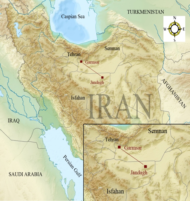 | Figure 1. Location map of study area |
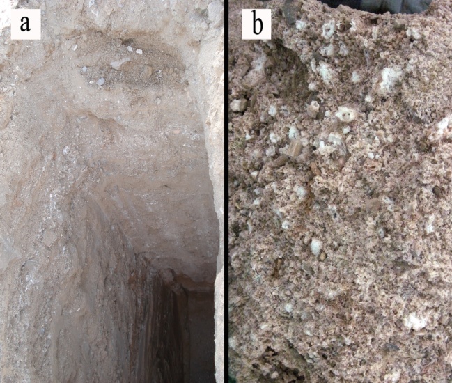 | Figure 2. Field bore hole and surface of untreated soil |
3.2. Lime
- The lime used in this study is a fine ground calcium hydroxide (Ca [OH] 2) provided from Iran-Qom limestone factory. Lime particles were finer than sieve No.60 (0.250mm).
3.3. Grand Granulated Blast Furnace Slag (GGBFS)
- The slag used in this study is Grand Granulated Blast Furnace Slag (GGBFS) obtained from Iron smelting factories (Iran-JAJROOD) in process of producing ST-37. GGBFS particles used in this study are milled and finer than Sieve No.200 (0.075mm).
3.4. Treatment Procedure
- In this experimental study, several numbers of specimens from the untreated silty sand soil and mixture of GGBFS-lime-soil were investigated.At the room temperature (25±°C), GGBFS was added in percentages of 5, 10, and 15% and lime was added in percentages of 1, 3, and 5%, by dry weight of the soil. The sand, GGBFS and lime were mixed thoroughly by hand until homogeneity and a uniform colour were reached. Water was added as needed to facilitate the mixing and compaction processes. In each case, modified proctor test performed to determine optimum water content and dry unit weight of untreated soil and mixtures. Compaction was performed with optimum water content determined in the compaction tests, just immediately after mixing, since the delay decreases the unconfined compressive strength[50], and have negative effect on CBR strength. The compacted specimens were cured for 7 and 28 days in tied plastic package to prevent loss of moisture content.Finally all samples were tested after curing time.
3.5. Mineralogical and Micro Structural Tests
- The mineralogy of the silty sand, GGBFS and Lime used in this research were identified by the X-Ray Diffraction technique (XRD). X-Ray powder diffraction analysis is a powerful method by which X-Rays of a known wavelength are passed through a sample in order to identify the crystal structure. Peak positions occur where the X-ray beam has been diffracted by the crystal lattice[51].Specific percentages of soil-lime and soil-GGBFS-lime mixtures were prepared and analysed under Scanning Electron Microscope (SEM) with 200 to 7,500 times magnification. SEM is used to generate images of the surface and the subsurface of specimen at magnifications in the range 20 x- 20000 x. It can be used to examine the micro-structure of specimens and to determine particle crystallinity. SEM may also be used to characterize and identify particular phases and their shape and forms[17].
3.6. Geotechnical Tests
- Various geotechnical experiments performed in this research such as, the grain size analysis, specific gravity of soil, the atterberg limits tests and the standard proctor compaction test. Unconfined compressive tests were strain-controlled. The rate of strain was maintained at 1 mm/min. In this test specimens were compacted using Harvard compaction hammer, in 5 layers by 25 hammer blows in each layer. Samples were made with 31mm diameter and 75mm length. Also CBR test were performed. In this test, the moulds were filled in five equal layers, and each layer was compacted by 10, 30 and 65 hammer blows (represented by N), then 2.26 kilograms overhead load was placed on the specimen to represent the weight of pavement layers. Moreover pH values and soil swelling potentials were evaluated.
4. Discussions
4.1. General Soils Specifications
- The mechanical aggregation test was done by using wet method and therefore minerals and salt were dissolved in water while washing the soil[52]. Hydrometer test was conducted based on the ASTM standard[52]. The grain size distribution of untreated soil sample has indicated that the soil is composed of 67.7% sand, 25% silt and 2% clay, and According to the Unified Soil Classification System (USCS), the sand can be classified as fine grained, silty sand (SM).It should be noted that about 30% of soil weight was found to be minerals and salts. Figure 3.shows the grain size distribution of the usedsilty sand soil.
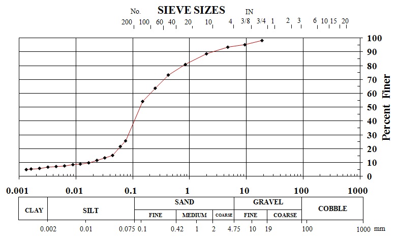 | Figure 3. Grain size distributions for desert sand |
4.2. X-Ray Diffraction Analysis and Chemical Composition of Materials
- X-ray diffraction (XRD) test was performed on soil, GGBFS and lime. Figure 4 illustrates X-Ray pattern of GGBFS.
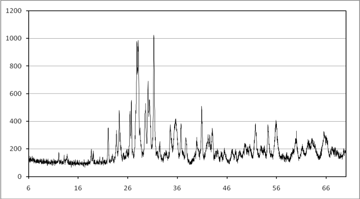 | Figure 4. X-Ray pattern of GGBFS |
|
|
|
4.3. PH Values
- In order to determine the optimum content of lime required for stabilisation, the pH value tests were conducted by using Eades& Grim method[59]. The pH values of untreated soil and soil-GGBFS mixtures were equal and found to be 7.6. So change in percentage of GGBFS does not make any change on the pH values. Then the pH tests were performed on the mixtures of soil-lime and soli-GGBFS-lime. Figure 5 shows the results of this analysis.Regarding to above results,the optimum amount of lime belongs to the sample which contains 10 % GGBFS and 1% lime. Maximum pH values were found in samples which contains 4% lime and different percentages of GGBFS. It should be noted that in general the lime addition increased the pH value of the samples. It was also observed that the pH value decreases in all mixtures when the lime content reaches to 5%.
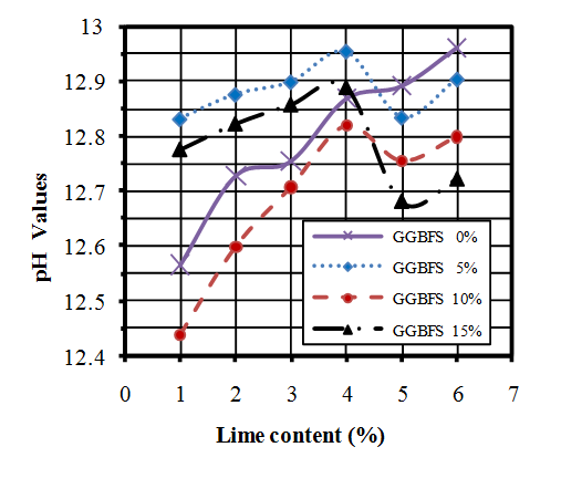 | Figure 5. pH values diagram of soil-GGBFS-lime mixtures |
4.4. Compaction Tests
- Compaction test is usually performed to re-arrange soil particles by mixing water with the soil[60].Themodified Proctor tests were performed in accordance with ASTM standard[61], for both untreated soil and soil-GGBFS-lime mixtures. The maximum dry unit weight of untreated soil was 20.1 (kN/m3) while the optimum water content was 9.96%. The results of the compaction tests for the various mixtures are shown in Table 4.
4.5. Unconfined Compressive Strength (UCS) Test
- Unconfined compressive strength (UCS) tests were performed based on ASTM standard[66]. The unconfined compressive strength of untreated soil was measured 160 (kN/m2). Three samples were prepared for each mixture and each curing time and they were cured for 7 and 28 days. The average values of every three samples were determined as results of the UCS tests. Results of performed UCS tests are presented in Figure 6.
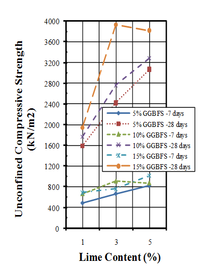 | Figure 6. Unconfined compressive strengths of samples |
4.6. California Bearing Ratio Test (CBR)
4.6.1. CBR Values
- California bearing ratio (CBR) tests were conducted in accordance with ASTM standard[68]. Wet condition was prepared for soil sample and mixtures by soaking 7 and 28 days cured samples in water for 4 days (96 hours).The results of CBR tests on untreated soil are shown in Table 5 and Figure 7. The un-soaked CBR values found to be higher than soaked CBR values.
| |||||||||||||||||||
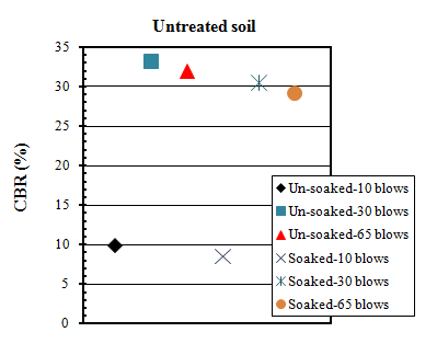 | Figure 7. Un-soaked and soaked CBR values of untreated soils |
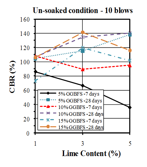 | Figure 8. CBR values of un-soaked samples compacted by 10 blows |
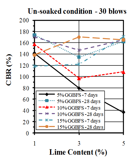 | Figure 9. CBR values of un-soaked samples compacted by 30 blows |
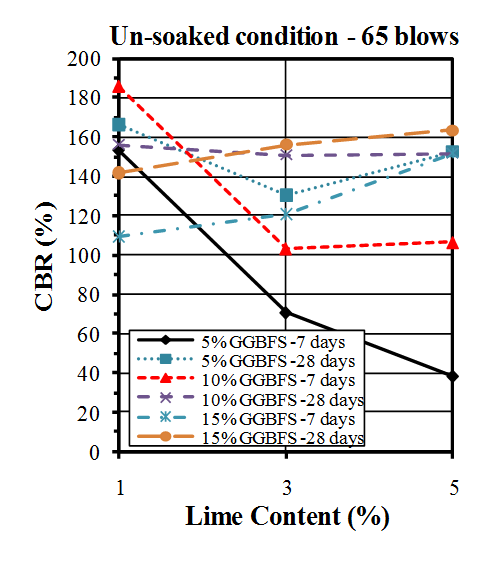 | Figure 10. CBR values of un-soaked samples compacted by 65 blows |
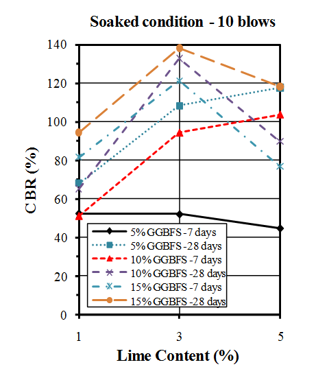 | Figure 11. CBR values of soaked samples compacted by 10 blows |
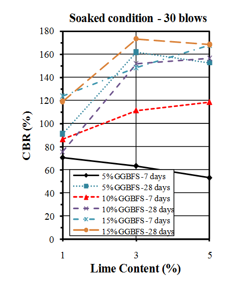 | Figure 12. CBR values of soaked samples compacted by 30 blows |
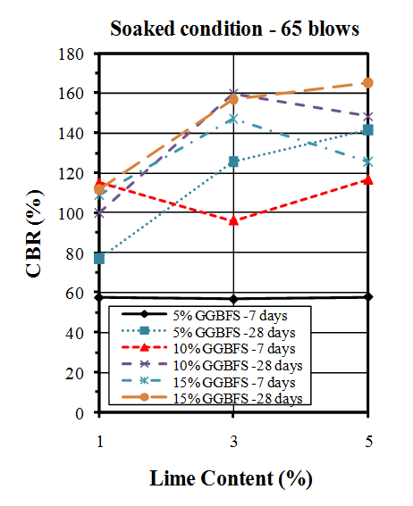 | Figure 13. CBR values of soaked samples compacted by 65 blows |
4.7. Swelling Values
- Swelling potential was measured during 4 days (96 hours), while samples were soaked in water.As shown in Figure 14, for the soil-lime mixtures, maximum swelling values were observed in presence of 1% lime and other mixtures which contain 3% and 5% lime shows less swelling values.
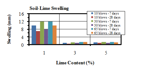 | Figure 14. Swelling values of soil-lime mixtures |
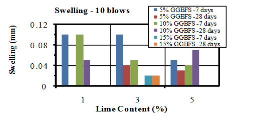 | Figure 15. Swelling values of soaked samples compacted by 10 blows |
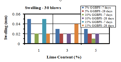 | Figure 16. Swelling values of soaked samples compacted by 30 blows |
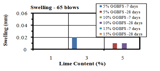 | Figure 17. Swelling values of soaked samples compacted by 65 blows |
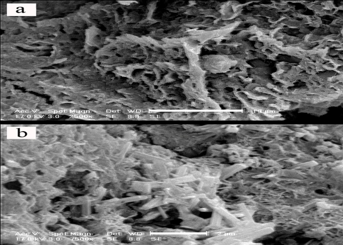
4.8. Scanning Electronic Microscopy
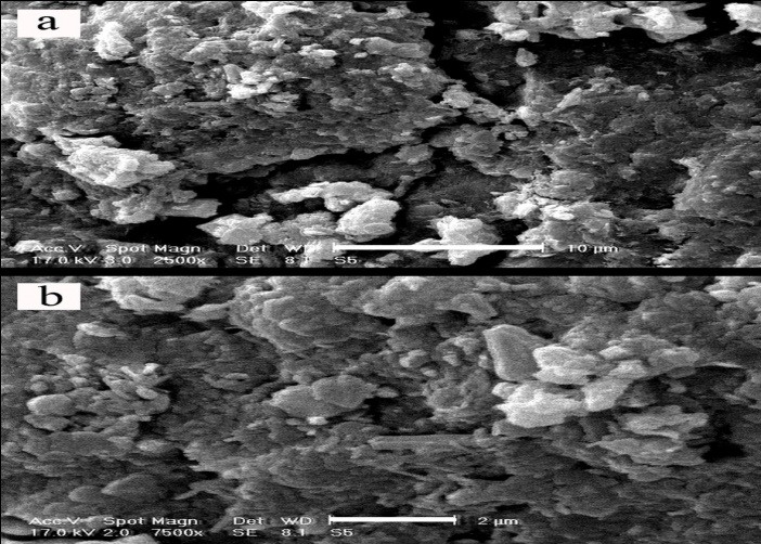
- In this set of experiment, in order to evaluate interaction between soil, GGBFS and lime, three samples were prepared and cured for 7 and 28 days. One sample contained 0% GGBFS and 5% lime and other two samples contained 1% lime and 10% GGBFS and 3% lime and 15% GGBFS. SEM analyses were conducted on samples with 200 to 7500 times magnifications. Figure 18, 19, 20, 21 and 22 present these results.The SEM analysis of sample with 5% lime and without GGBFS is shown in Figure 18. It can be seen that the soil particles were slightly coated and surrounded with lime and minerals had spherical shape.It can be found from Figure 19, 20, 21 and 22 that curing time can play an important role in stabilising of samples.Regarding to 7 and 28 days cured samples, it can be seen that soil has become denser in a time dependent manner and there are less voids available after 28 days curing. It seems that producing of cemented materials is because of pozzolanic reactions between soil, GGBFS and lime. Most soil particles were covered by silica and alumina hydrate gels which cussed forming cementitious structure of the materials and subsequent crystallisation to bind the structure together. The voids became smaller, so pore spaces have reduced significantly and a denser structure obtained and this event can reduce the permeability of the samples. These results were in parallel with above presented CBR and UCS tests results. In Figure 22, the angular shape of particles can be seen clearly.
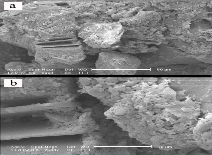 | Figure 18. Soil-lime mixture x500 - 50µm and x2500 - 10µm, 5% lime |
 | Figure 19. 1% lime 10% GGBFS mixture, x2500 -10µm and x7500 -2 µm, 7 days cured |
 | Figure 20. 1% lime 10% GGBFS mixture, x2500 – 10µm and x7500 - 2µm, 28 days cured |
 | Figure 21. 3% lime 15% GGBFS mixture, x2500 - 10µm and x7500 - 2µm, 28 days cured |
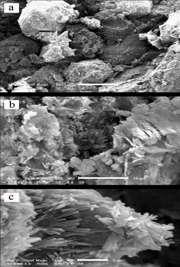 | Figure 22. 3% lime 15% GGBFS mixture, x200 - 100µm, x2500 - 10µm and x7500 - 2µm, 28 days cured |
5. Conclusions
- In this study mixture of GGBFS and lime were utilized as a soil stabiliser to improve engineering properties of desert silty sands. The following conclusions were derived from this experimental research:•Adding lime to the silty sand has increased the pH value of the samples, but generally addition of GGBFS has no effect on pH values.•Lime addition has reduced the maximum dry unit weight and has increased the optimum water content of silty sand.Also addition of GGBFS has increased the maximum dry density and optimum water content of samples.•Generally as the lime content increased the unconfined compressive strengths of mixtures were increased too and GGBFS addition has increased the unconfined compressive strength of mixtures.•Results of CBR tests showed that when untreated soil has mixed with various percentages of GGBFS and lime, the un-soaked and soaked CBR values of samples have increased significantly, but soaked samples shows lower CBR values in compare with un-soaked samples.•GGBFS addition has increased the CBR values of mixtures, especially in presence of 3% and 5% lime.•In general, samples compacted by 30 blows in each layer shows higher CBR values than other samples compacted by 10 and 65 blows.•Increasing curing time from 7 to 28 days had a considerable effect on increasing the unconfined compressive strength and CBR values.•Addition of GGBFS has significantly reduced the swelling ratio of mixtures.•It was seen that mixtures compacted by 65 blows in each layer show the minimum swelling values than other mixtures compacted by 10 and 30 blows.• the optimum lime-GGBFS ratio to achieve the maximum unconfined strength and CBR values is 1: 5 and the maximum measured UCS and CBR values are for sample with 3% lime and 15% GGBFS.•Due to the large volume of GGBFS which is produced as a waste material in the world, GGBFS can be considered as an economical and valuable material with lots of positive effects to increase the engineering properties of soils.
ACKNOWLEDGEMENTS
- Financial support for this study was provided by the “KEYHAN KHAK “soil mechanics and concrete Company which is located in KARAJ-IRAN.
References
| [1] | Mohamedzein, Y. E. A., AL-AGHBARI, M. Y., &Taha, R. A. (2006). Stabilisation of desert sands using municipal solid waste incinerator ash. Geotechnical and Geological Engineering 24, 1767-1780. |
| [2] | Elsharief, A. M., Mohamedzein, Y. E. A., &Hussien, Y. (1999). Geotechnical properties of Qoz soil. Proceedings of the Twelfth Regional Conference for Africa on Soil Mechanics and Geotechnical Engineering, 317-320. |
| [3] | Bell, F.G. (1993), Engineering Treatment of Soils, Spon Press, London, UK. |
| [4] | Aiban, A. (1994). Study of sand stabilisation in Eastern Saudi Arabia. Journal of Engineering Geology 38, 65-67. |
| [5] | Mohamedzein, Y. E. A., Al-Rawas, A. A., & Al-Aghbari, M. Y. (2003). Assessment of Sand– Clay Mixtures for Use in Landfill Liners. Proceedings of the International Conference on Geo-environmental Engineering, 211-218. |
| [6] | Baghdadi, Z. A., &Rahman, M. A. (1990). The Potential of cement kiln dust for the stabilisation of dune sand in highway construction. Building and Environment 25, No.4, 285-289. |
| [7] | Freer-Hewish, R. J., Ghataora, G. S., &Niazi, Y. (1999). Stabilisation of desert sand with cement kiln dust plus chemical additives in desert road construction. Proceedings of the Institution of Civil Engineer, Transport, 135, No. 1, 29-36. |
| [8] | O’Sadnick, D. L., Simpson, B. E., &Kasel, G. K. (1995). Evaluation and performance of a Sand/Bentonite Liner. Proceedings of a Specialty Geoenvironment 2000, ASCE, New Orleans, Louisiana, USA, 688-701. |
| [9] | Taha, R. A., &Pradeep, M. R. Use of fly Ash–Stabilised Sand Mixtures as Capping Materials for Landfills. Proceedings of the Symposium on Testing Soil with waste or Recycled Materials, ASTM. New Orleans, Louisiana, USA, 1997, pp.172-180 |
| [10] | Turner, J. P. (1997). Evaluation of Western coal fly ashes for stabilisation of low-volume roads. Proceedings of the 1997 Symposium on Testing Soil with waste or Recycled Materials, ASTM, New Orleans, Louisiana, USA, 157-171. |
| [11] | Consoli, N. C., Montardo, J. P., Prietto, P. D. M., &Pasa, G. S. (2002). Engineering behavior of a sand reinforced with plastic waste. Journal of Geotechnical and Geoenvironmental Engineering, ASCE 128, No. 6, 462-472. |
| [12] | Wahab, H. I. A. &Asi, I. M. (1997). Improvement of marl and dune sand for highway construction in arid areas. Journal of Building and Environment 32, No. 3, 271-279. |
| [13] | Ingles, O. G., & Metcalf, J. B. Soil Stabilisation: Principles and Practice. Sydney, Butterworths, 1972, pp. 127-167. |
| [14] | Al-Khanbashi, A., Mohamed, A. M. O., Moet, A., &Hadi, B. Stabilisation of desert sand using water-borne polymers. First International Conference on Geotechnical, Geoenvironmental Engineering and Management in arid Lands, United Arab Emirates, 2000, pp.143-148. |
| [15] | Kaniraj, S. R., &Havanagi, V. G. (2001). Behavior of cement-stabilised fiber-reinforced fly ash-soil mixtures. Journal of Geotechnical and Geoenvironmental Engineering, ASCE 127, No. 7, 574-584. |
| [16] | Bhuyan, S., & Singh, S. P. (2010). Stabilisation of balast furnace slag and fly ash using lime and Rbi grade 81. BS Thesis, Department of Civil Engineering, National Institute of Technology Rourkela, India. |
| [17] | Abdel RahmanOuf, M. E. S. (2001). Stabilisation of clay subgrade soil using ground granulated ballast furnace slag. PhD Thesis, University of Leeds, U.K. |
| [18] | Axelsson, K., Johansson, S. E., &Andersson, R. (2000). Stabilisation of Organic Soils by Cement and Pozzolanic Reactions. Feasibility study, Swedish Geotechnical Institute,Swedish Deep Stabilisation Research Centre. |
| [19] | Higgins, D. D., Kinuthia, J. M., & Wild, S. (1998). Soil Stabilisation Using Lime-Activated GGBS. Proceedings of the 6th. Conference, Fly Ash, Silica fume, Slag, and Natural Pozzolans in Concrete 2, 1057-1074. |
| [20] | Gupta, S., &Seehra, S. S. (1989). Studies on Lime Granulated Blast Furnace Slag as an Alternative Binder to Cement. Highways Research Board, Bulletin, No. 38, 81-97. |
| [21] | Gjorv, O. E. (1989). Alkali Activation of Norwegian Granulated Blast Furnace Slag. Proceedings of the Third International Conference Trondheim 2, 1501-1517. |
| [22] | Sherwood, P. T. Soil stabilisation with Cement and Lime- state of the art review: HMSO Publication, London, 1993. |
| [23] | Serruto, M., &Pardo, L. (2001). Evaluation of Stabilised Marginal Pavement Materials Using Established and Newly Developed Cementitious Binders. 20th ARRB Conference Melbourne. |
| [24] | Meggs, R. Stabilisation- Cementitious blends incorporating GGBFS (Technical Note 15): VicRoads Materials Technology Department, Victoria, Australia. 1996. |
| [25] | McDowell, C. (1966). Evaluation of Soil-Lime Stabilisation Mixtures. Highway Research Record, No.139, 15-24. |
| [26] | Bell, F. G. (1996). Lime Stabilisation of Clay Minerals and Soils. Engineering Geology 42, 223-237. |
| [27] | Kavak, A., Keskin, E., &Akyarh, A. (2007). A field application for lime stabilisation. Environ Geol 51, 987-997. |
| [28] | Mallela, J., Quintus, H. V., & Smith, K. L. (2004). Consideration of Lime-Stabilised Layers in Mechanistic-Empirical Pavement Design. The National Lime Association. |
| [29] | Rogers, C. D. F., Glendinning, S., &Roff, T. E. J. (1997). Lime Modification of Clay Soils for Construction Expediency. Proceedings of the Institution of Civil Engineers, Geotechnical Engineering 125, 242-249. |
| [30] | Bell, F. G., &Coulthard, J. M. (1990). Stabilisation of Clay Soils with Lime. Proceedings of the Institution of Civil Engineers, Municipal Engineer, No.7, 125-140. |
| [31] | Bari, F. (1995). Stabilisation of Clay Soils with Lime. MSc Thesis, University of Leeds, U.K. |
| [32] | Thompson, M. R. (1966). Lime Reactivity of Illinois Soils. Journal of Soil Mechanics and Foundations Division, ASCE 92, 67-91. |
| [33] | Kavak, A. (1996). The behavior of lime stabilised clays under cyclic loading. Ph.D. dissertation, Bogazici University. Istanbul. |
| [34] | Kavak, A., & Baykal, G. I. (2001). behavior of lime-stabilised clays subjected to repeated loading. Proceedings of the 15th international conference on soil mechanics and geotechnical engineering, Istanbul. |
| [35] | Thompson, M. R. (1969). Engineering properties of lime-soil mixtures. Journal of materials, JMLSA, 4, No. 4, 968-969. |
| [36] | Newbauer, C. H., & Thompson, M. R. (1972). Stability properties of uncured limetreated fine grained soils. Highway Research Recor, No. 381, National Research Council, Washington DC, 20-26. |
| [37] | Rao, S., &Shivananda, P. (2005). Impact of Sulphate Contamination on Swelling Behavior of Lime-Stabilised Clays. Geotechnical Testing Journal, ASTM 2,No.4, 1-10. |
| [38] | Wang, L. (2002). Cementitouse Stabilisation of Soils in the Presence of Sulphate. PhD Theses, Louisiana State University. U.S.A. |
| [39] | Mitchell, J. K. (1986). Delayed Failure of Lime-Stabilised Pavement Bases. Journal of Geotechnical AndGeoenvironmental Engineering, ASCE 112, 274-279. |
| [40] | Hunter, D. (1988). Lime-induced heave in sulphate-bearing clay soils. Journal of Geotechnical AndGeoenvironmental Engineering, ASCE 114, 150-167. |
| [41] | Snedker, E. A. & Temporal, J. (1990). M40 motorway Banbury IV contract - Lime Stabilisation. Institution of Highways & Transportation, London, U.K. 37,No.12, 7-8. |
| [42] | Wild, S., Kinuthia, J. M., Jones, G. I., & Higgins, D. D. (1999). Suppression of swelling associated with ettringite formation in lime-stabilised sulphate-bearing clay soils by partial substitution of lime with ground granulated blast furnace slag. Engineering Geology 51, 257-277. |
| [43] | Veith, G. H. (2000). Engineering Properties of Sulphate-Bearing Clay Soils Stabilised with Lime Activated GGBS. PhD thesis, Glamorgan, U.K. |
| [44] | Higgins, D. D. (2005). Soil Stabilisation with Ground Granulated Blast furnace Slag. UK Cementitious Slag Makers Association (CSMA). |
| [45] | Wild, S., &Tasong, W. A. (1999). Influence of Ground Granulated Blast furnace Slag on the Sulphate Resistance of Lime- Stabilised Kaolinite. Magazine of Concrete Research 51, No. 4, 247-254. |
| [46] | Yamanouchi, Y., Monna, I., & Hirose, T. (1982). Seepage-Cut- Soil Stabilisation with Newly Developed Slag-Cement. Symposium on Recent Development in Ground Improvement Techniques, Bangkok, 507-511. |
| [47] | Regourd, M. (1980). Structure and Behavior of Slag Portland Cement Hydrates. 7th International Congress on the Chemistry of Cement, Paris, France, Sub-Theme 111-2, 2, 10-26. |
| [48] | Kinuthia, J. M. (1997). Property changes and mechanisms in lime stabilised Kaolinite in the presence of metal sulphates. PhD Thesis, University of Glamorgan. U.K |
| [49] | Thomas, B. (1999). Strength Development Durability and Linear Expansion of Sulphide Rich Clay Soils Stabilised With Lime Activated GGBS. PhD Thesis, University of Glamorgan, U.K. |
| [50] | Bin-Shafique, S., Edil, T. B., Benson, C. H., &Senal, A. (2004). Incorporating a fly-ash stabilised layer into pavement design. Proceedings of the Institution of Civil Engineers - Geotechnical Engineering 157, No.4, 239-249. |
| [51] | Warren, B. E. X-ray Diffraction, Dover Publications, New York, 1990. |
| [52] | ASTM (American Society for Testing and Materials) (2002). Standard Test Method for Particle-Size Analysis of Soils,D422–63. West Conshohocken, PA: ASTM. |
| [53] | ASTM (American Society for Testing and Materials) (2002). Standard Test Methods for Specific Gravity of Soil Solids by Water Pycnometer, D854–02. West Conshohocken, PA: ASTM. |
| [54] | ASTM (American Society for Testing and Materials) (2002). Standard Test Methods for Liquid Limit, Plastic Limit, and Plasticity Index of Soils, D4318-00, West Conshohocken, PA: ASTM. |
| [55] | Klein, C., &Hurlbut, C. S., Manual of Mineralogy, 20th edn, John Wiley, New York, 1985, pp. 352–353, ISBN 0-471-80580-7. |
| [56] | Iler, R. K. The Chemistry of Silica. Wiley-Interscience: New. York, 1979.ISBN047102404X. |
| [57] | Lynn Townsend White, J. R. (1961). A Case Study of Technological Innovation, Its Context and Tradition. Technology and Culture(Society for the History of Technology) 2, No.2, 97-111. |
| [58] | Greenwood, N. N., &Earnshaw, A. Chemistry of the Element, 2nd edn.Butterworth Heinemann, Oxford, London, 1997.ISBN0-7506-3365-4. |
| [59] | Eades, J. E., & Grim, R. E. (1963). a Quick Test to Determine Lime Requirements for Lime Stabilisation. Highway Research Board, Record No. 139, pp 61–72. |
| [60] | Chen, L., & Lin, D. F. (2009). Stabilisation treatment of soft subgrade soil by sewage sludge ash and cement. Journal of Hazardous Materials 162, 321-327. |
| [61] | ASTM (American Society for Testing and Materials) (2002).Standard Test Methods for Laboratory Compaction Characteristics of Soil Using, D1557-02. West Conshohocken, PA: ASTM. |
| [62] | Little, D. N. Handbook for Stabilisation of Pavement Sub- Grade and Base Courses with Lime. National Lime Association: Kendall Hunt Publishing Company.Lowa, USA, 1995. |
| [63] | Rogers, C. D. F. (1988). Lime Stabilisation. Ground Engineering, 7-10. |
| [64] | Akinmusuru, J. O. (1991). Potential Beneficial Uses of Steel Slag Wastes for Civil Engineering Purposes. Resources Conservation and Recycling 5, 73-80. |
| [65] | Wild, S., Kinuthia, J. M., Robinson, R. B., & Humphreys. (1996). Effects of Ground Granulated Blast Furnace Slag (GGBS) on the Strength and Swelling Properties of Lime - Stabilised Kaolinite in The Presence of Sulphates. Clay Mineralogy, No. 31, 423-433. |
| [66] | ASTM (American Society for Testing and Materials) (2002). Standard Test Method for Unconfined Compressive Strength of Cohesive Soil, D2166–00. West Conshohocken, PA: ASTM. |
| [67] | Cabrera, J. G., &Nwakanma, C. A. (1979). Pozzolanic Activity and Mechanism of Reaction of Red Tropical Soil-Lime System. Transportation Research Record, National Research Council, Washington D.C. No.702, 199-207 |
| [68] | ASTM (American Society for Testing and Materials) (2002). Standard Test Method for CBR (California Bearing Ratio) of Laboratory-Compacted Soils, D1883–99. West Conshohocken, PA: ASTM. |