-
Paper Information
- Next Paper
- Previous Paper
- Paper Submission
-
Journal Information
- About This Journal
- Editorial Board
- Current Issue
- Archive
- Author Guidelines
- Contact Us
Journal of Civil Engineering Research
p-ISSN: 2163-2316 e-ISSN: 2163-2340
2012; 2(6): 73-83
doi: 10.5923/j.jce.20120206.04
Shear Strengthening of R/C Beams with FRP Strips and Novel Anchoring
G. C. Manos , Κ. Katakalοs , G. Koidis , C. G. Papakonstantinou
Laboratory of Strength of Materials and Structures Department of Civil Engineering, Aristotle University of Thessaloniki, 54006, Thessaloniki, Greece
Correspondence to: G. C. Manos , Laboratory of Strength of Materials and Structures Department of Civil Engineering, Aristotle University of Thessaloniki, 54006, Thessaloniki, Greece.
| Email: |  |
Copyright © 2012 Scientific & Academic Publishing. All Rights Reserved.
The shear strengthening behaviour of R/C beams, when applying FRP strips externally with or without anchoring, is studied. This is done by subjecting six specimens of prototype dimensions with or without such strengthening to four-point bending. Specimens strengthened with either carbon or steel FRP strips without the use of anchors exhibited a modest increase in shear capacity, when compared to the non-strengthened control specimen, due to the debonding mode of failure of these FRP strips. The patented anchoring device was utilized together with either carbon or steel FRP strips for shear strengthening. In this case, the FRP strips debonding failure was prevented and the increase of the shear capacity was much larger than in identical specimens without anchors. An expert system developed for this purpose is quite efficient in producing successful shear capacity predictions based on the provisions of various codes. The Greek Code for retrofitting existing R/C structures yields shear capacity predictions in good agreement with measured values.
Keywords: Strengthening R/C beams, Upgrading Shear Capacity, FRP Sheets, Novel Anchoring Devices, Monotonic Loading Conditions
Cite this paper: G. C. Manos , Κ. Katakalοs , G. Koidis , C. G. Papakonstantinou , "Shear Strengthening of R/C Beams with FRP Strips and Novel Anchoring", Journal of Civil Engineering Research, Vol. 2 No. 6, 2012, pp. 73-83. doi: 10.5923/j.jce.20120206.04.
Article Outline
1. Introduction
- Many reinforced concrete (R/C) structural members of old buildings need strengthening. This is either because they were built according to old code provisions and do not meet the current design requirements, or because they are damaged after a strong earthquake sequence. Strips made of fiber reinforcing polymers (FRP) behave in tension almost elastically till their ultimate state; this for the material itself is the breaking of the fibers in tension. The value of the Young’s modulus is approximately 240Gpa for carbon fibers, 200Gpa for steel fibers and 80Gpa for glass fibers ([1] to[4]). Their design ultimate axial strain values are in the range of 1%. Consequently, strips made from these materials, despite their relatively small thickness which is usually below 0.2mm for one layer, can develop substantial tensile forces in the direction of their fibers. This property accompanied by their low weight and their very easy external attachment results in their being used as effective transverse reinforcement for structural elements in need of shear capacity upgrading (figure 1 and[1] to[6]). A wide range of fiber reinforced composite materials have been successfully used in the past for the repair and strengthening of existing R/C structures[1]. Strengthening with externally bonded FRPs is particularly common, due to the speed and ease of installation, their low weight and high tensile strength[3].
 | Figure 1. Shear FRP reinforcement for a rectangular beam |
2. Initial Tests Assessing the Effectiveness of Anchoring
- Initially, the effectiveness of anchoring devices for an FRP strip was investigated by utilising a number of concrete prismatic specimens representing a part of an R/C beam of prototype dimensions. These specimens can house one such open hoop FRP strip with sufficient width and length (Figure 2, part a-a and part b-b). In all, ten such specimens were fabricated and tested being subjected to the loading arrangement depicted in figure 3. Five of these specimens had CFRP strips, whereas SFRP strips were attached to the remaining five. The use of the anchoring device was also utilised selectively with a number of these specimens as follows.
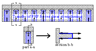 | Figure 2. RC beam strengthened with FRP strips as transverse reinforcement |
2.1. Experimental Set-up
- All concrete prisms were fabricated using the same concrete mix and the same internal reinforcement, which was used to prohibit any accidental failure (figure 3). The measured cylinder strength of the concrete was equal to 22 MPa. The properties of the used FRP’s are listed in Table 1, as given by the manufacturers.
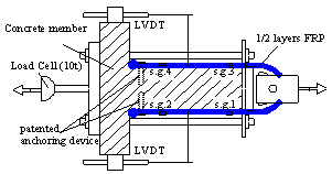 | Figure 3. Experimental set-up used in the initial tests |
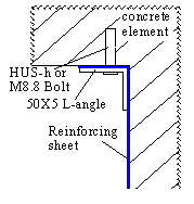 | Figure 4. Type 1 Anchor |
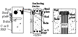 | Figure 5. Type 2 Anchor (Patented under WO2011073696[11]) |
2.2. Experimental Results and Discussion
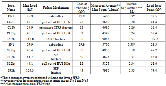
- The summary of the experimental results is shown in table 3. In this table, the observed failure mechanism is also listed together with the corresponding value of the ultimate measured load as well as the value of the load recorded at the initiation of debonding. Moreover, the maximum strain values measured by the strain gauges at locations 1 and 3 on the FRP strip surface are also listed. The average value of these maximum FRP strains was utilised to calculate indirectly the load sustained by the FRP strips taking into account their total cross-sectional area and the value of the Young’s modulus, listed in table 1. Finally, the material exploitation indicator (Me) is given at the same table as the ratio of the maximum measured strain by the ultimate strain value provided by the manufacturer (Table 1).
|
|
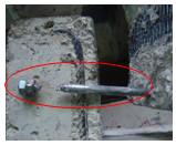 | Figure 6. Failure of anchor Type1 |
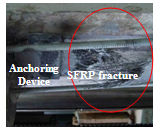 | Figure 7. Fracture of SFRP (Type2) |
3. Application of Anchored Open-hoop FRP Strips to R/C Beam Specimens
- In this section, the shear behavior of reinforced concrete (R/C) rectangular beams with or without open-hoop FRP transverse reinforcement is presented and discussed. They were tested in four-point bending (Figure 9) up to failure either in their virgin state or being strengthened with open-hoop FRP transverse reinforcement, in the form of FRP strips with or without anchoring. Alternatively, this FRP shear strengthening scheme was applied after the virgin specimens reached failure in the framework of repair and strengthening of such damaged R/C structural elements.
3.1. Experimental Set-up
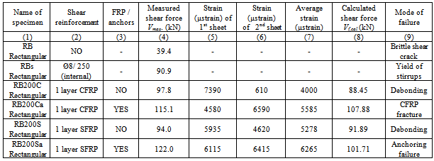
- In this section, results from a total number of six reinforced concrete (R/C) rectangular beam specimens will be presented. Their cross-section was 120mm wide and 360mm deep (Figure 8). Their overall span was 2700mm whereas the shear span was equal to 900mm (1/3 of the total length). These rectangular section beam specimens were simply supported and loaded up to failure. Instrumentation was provided to monitor the applied load as well as the deformation of these specimens (Figure 9). Strain gauges were placed on every FRP strip in order to record the developed strains on them. The strain gauges were placed along the direction of carbon or steel fibers, at the mid-distance of both width and height of the sheet, due to the fact that that the shear cracks are difficult to predict. The cross-sections and conventional steel reinforcement details were identical for all specimens (Figure 8). Three 20 mm diameter steel rebars were positioned longitudinally at the top and bottom of the beam section. No stirrups were placed in these beams. The strengthening scheme consisted of either uniaxial CFRPs or uniaxial high strength steel fiber (SFRP) sheets combined with a commonly used organic resin. Table 1 presents the properties of the strengthening materials. These sheets were attached externally on the specimens as transverse (shear) reinforcement (Figures 1 and 2). The width of the sheets was kept constant and equal to 100mm, whereas the axial distance between these sheets was also constant and equal to 200mm. Type 2 anchoring device (Figure 5) was used for the FRP strips in two specimens. Table 4 summarizes the specimens’ properties.
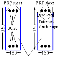 | Figure 8. Cross section of the rectangular beam specimens with reinforcement details (dimensions in mm) |
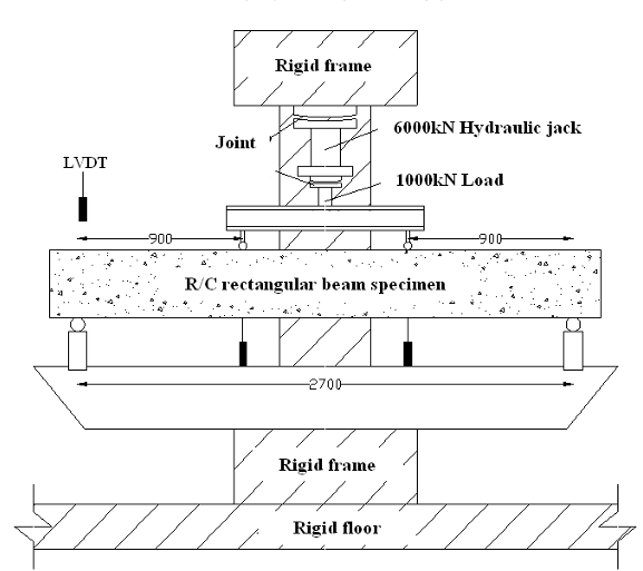 | Figure 9. Experimental set-up for the four-point bending of the rectangular cross-section specimens (dimensions in mm) |
|
|
3.2. Increase of Strength – Modes of Failure
- For all specimens, the applied load and the vertical displacements were recorded as well as the strains at each FRP sheet. Table 4 lists the measured values from this experimental investigation. The measured shear capacity is listed in column 4 of Table 4 whereas the measured maximum strain values of the attached FRP sheets that the shear crack intersects are listed in 5th and 6th columns of the same table.The shear strength of the control rectangular beam (RB) without any stirrups or CFRP/SFRP strips was recorded equal to 39.4kN, whereas the shear capacity of specimen RBs with stirrups Ø8/250mm as transverse reinforcement was increased to 90.9kN. From the results shown in Table 4, it is evident that the maximum recorded shear capacity for all strengthened rectangular beams with CFRP/SFRP strips was significantly greater than that of either the RB or the RBs shear capacity (see also Table 5). Without anchors, the shear capacity increase was limited to 138%, due to the debonding mode of failure of the CFRP strips (figure 10). The specimen strengthened with SFRP strips exhibited an increase in the shear capacity of up to 210% when anchors were utilized. For this specimen, the mode of failure was the pull-out of the anchoring system (figure 11). When the shear capacity of the strengthened specimens is compared to that of the virgin specimen with nominal transverse reinforcement in the form of steel stirrups the resulting maximum shear capacity increase is equal to 7.6% when using CFRP strips without anchors and 34.2% when using SFRP strips with anchors (see table 5). The beneficial effect of anchoring the U-shape open-hoop FRP strips in order to inhibit the debonding mode of failure is thus demonstrated.
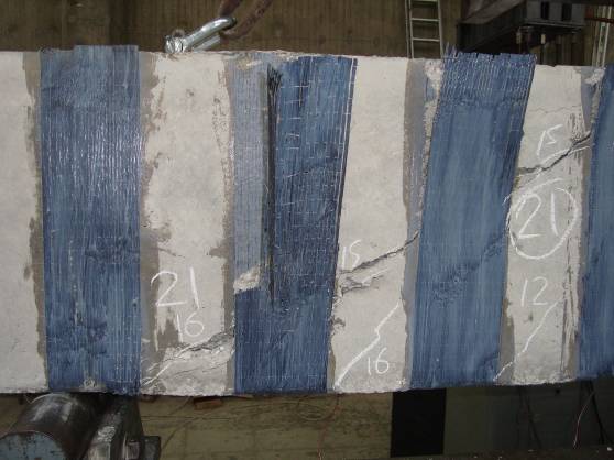 | Figure 10. CFRP debonding |
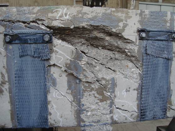 | Figure 11. CFRP failure of the anchoring |
3.3. Shear Force – Beam Deflection Response
- Shear force – beam deflection response envelope curves are depicted in figure 12. When anchors are used together with the FRP strips, the increase in the shear capacity is also accompanied by an increase in the measured maximum beam deflection.
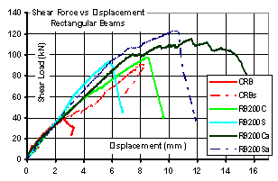 | Figure 12. Shear force – vertical displacement response envelope curves for the rectangular beam specimens |
3.4. CFRP-SFRP Strains
- In order to evaluate the shear resistance contribution offered by either the CFRP or the SFRP sheets, strain gauges were attached at mid-height and mid-width of each FRP sheet along the direction of the fibers. It should be mentioned that the strain values for each specimen reported here are the measured maximum strain values from strain gauges corresponding to those FRP sheets that were intersected by the main shear crack which developed during the loading sequence. These measured maximum FRP strip strain values are listed in table 4 (columns 5 and 6) together with the serial number of the corresponding FRP strip. Those recorded maximum strain values are next employed as maximum average strain values (Table 4 col. 7) in order to obtain the shear force that is contributed by the FRP sheets. As already mentioned, the existence of an anchoring device allows the development of greater strains on FRP sheets compared to the cases where no anchoring device is in place. The highest measured shear capacity value was obtained for specimen RB200Sa (122KN, Table 4) where the used SFRP developed maximum average strain value equal to 6265με (Table 4 col. 7). The use of anchoring prevented the premature delamination mode of failure of the FRP strip; instead, the failure of the anchoring occurred in this specimen (see Table 4). Through proper detailing of the patented anchor this anchoring failure could be prohibited, thus further enhancing the shear capacity of this specimen. In contrast, for specimens strengthened with FRP strips without the use of anchors, the maximum FRP strains and the corresponding shear force values were kept to significantly lower levels (average of 4644με). This observation indicates that the use of anchors results in better utilization and performance of the FRP material for shear strengthening. According to the recommendations of either ACI 440-08[19] or FIB[18], the maximum effective FRP strain that can be utilized should be limited to 0.004 mm/mm (see section 4.1). Eurocode[17] does not provide a specific FRP strain limit; the effective strain is calculated using formulas that depend upon the strengthening scheme. These recommended relatively small strain values are based on the assumption that typical composite materials do not cope well with stress concentrations that occur at the corners of the FRP strips as they are wrapped around the beam. This precaution is not necessarily applicable when using steel fiber strips for shear reinforcement as they are tougher than strips made by either carbon or glass fibers. During the experimental sequence, none of the SFRP strips attached as shear reinforcement developed any type of failure at its steel fibers at the bottom corners of the strengthened specimens. Finally, it is evident that SFRP strips, with modulus of elasticity similar to that of CFRP strips, can develop much higher stresses and therefore perform better than the corresponding CFRP strips for shear strengthening applications of R/C beams.
4. Analytical Predictions
- Based on these strain recordings, the maximum shear capacity Vcal was obtained (Table 4 col. 8). This is compared to the experimental maximum shear force Vmax (Table 4 col. 4). Values of Vcal were found through equation (1):
 | (1) |
 | (2) |
 | (3) |
|
4.1. Brief Description of an Expert System
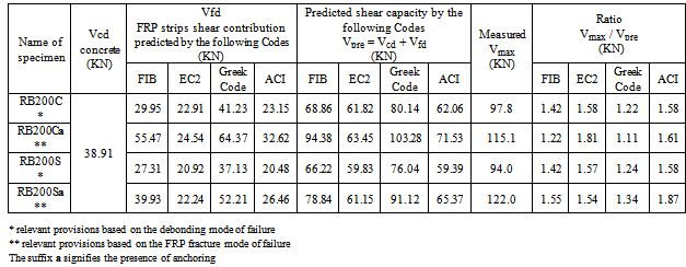
- The calculated shear capacity values listed in table 4 are based on the FRP shear contribution obtained from the measured FRP strip strain values. In this section, the measured shear capacity will be compared with predictions based on relevant code provisions, assuming the value of all the safety factors for the materials is equal to 1.0. In order to facilitate the calculation of such code predictions, an expert system was developed. The main features of this expert system are as follows. The section geometry and the longitudinal and transverse reinforcing details are given by the user through the appropriate user-friendly interface. Rectangular as well as T-beam reinforced concrete sections are alternative options of this expert system (see figure 13). The details of a strengthening scheme, utilizing externally attached FRP strips, can also be input through the same interface. The given options for such a strengthening scheme of an R/C cross-section is for enhancing either the flexural capacity or the shear capacity. The former is done by placing FRP sheets at the bottom of the R/C section and the latter by placing transverse shear reinforcing FRP strips. For the latter case, the strips can be either closed hoops or open-hoop U-strips (Figure 13). The actual properties of the concrete, the steel and the FRP strips are easily input by the user.The safety factors commonly used in design for all these materials, have their default values that can be subsequently changed by the user to alternative desired values. The results are given in terms of ultimate flexural and shear capacity. For evaluating the shear contribution of the FRP strips, use is made of the relevant provisions of the Greek Code for the repair of R/C structures[16] as well as those of the EuroCode-EC8[17], FIB[18] and ACI[19]. The shear contribution of the FRP strips in table 7 was obtained assuming a nominal ultimum strain value equal to 0.018 and 0.015 for CFRP or SFRP strips, respectively (see table 1). The Greek Code provisions assume a maximum FRP strain value equal to ½ of this nominal ultimate strain value. Specimens RB200C and RB200Ca are of rectangular cross-section with U-shape CFRP strips. More specifically, specimen RB200C has U-shape FRP strips without anchoring whereas specimen RB200Ca has U-shape FRP strips with anchoring. Table 7 lists the predicted by the expert system shear capacity values of the tested rectangular specimens, strengthened with FRP strips with or without anchoring. Moreover, these predicted values are compared with the measured shear capacity values by finding the ratio of the measured vs. predicted shear capacity values (Vmax / Vpre ). The values of this ratio are listed at the far right columns of table 7. As can be seen in this table, the Greek Code for retrofitting existing R/C structures[16] yields shear capacity predictions that are closer to the measured values than the corresponding predictions made by the rest of the codes. The measured shear capacity is 11% to 34% larger than the corresponding Greek Code predictions whereas they are 22% to 87% larger than shear capacity predictions made by the rest of the Codes ([17],[18],[19]).
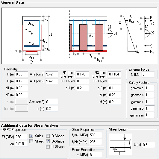 | Figure 13. Expert system utilized for specimens RB200C and RB200Ca |
|
5. Conclusions
- • Steel Fiber Reinforced Polymers (SFRP) that were specially fabricated for this specific research program could be successfully used as an alternative material for shear strengthening of R/C beams.• Reinforced Concrete beams that were strengthened with either CFRP or SFRP strips without the use of the anchors exhibited a modest increase of the shear capacity, when compared to the non-strengthened control specimen. This is due to the debonding mode of failure of the FRP strips. • When the patented anchoring device was utilized together with either CFRP or SFRP reinforcing strips for shear strengthening, the increase of the shear capacity was much larger than in identical specimens without anchors. This shear capacity increase attained a maximum value of 220% when compared to the shear capacity of the control beam without any transverse reinforcement (either steel stirrups or FRP strips).• Both measured maximum displacement values and maximum FRP strain values are significantly higher for specimens with anchored FRP strips than without anchors. For similar specimens, the measured maximum FRP strain values in the case of SFRP strips were higher than in the case of CFRP strips, thus resulting in a much better performance. • The use of FRP strips with anchoring devices transforms the overall behavior of the strengthened beams from a rather elastic-brittle to a relatively less brittle behaviour. This is achieved when the shear strengthening scheme is designed in such a way that the flexural mode of failure finally prevails for the specific structural member.• An increase of the post cracking stiffness was observed for all strengthened specimens. This was more pronounced for specimens with FRP strips utilizing anchors.• The analytical predictions of the shear capacity agree quite well with the corresponding measured values. • The developed expert system is quite efficient in producing shear capacity predictions based on the provisions of various codes. In all examined cases, the measured shear capacity values are larger than the corresponding values obtained by applying the various code provisions, which are based on rather low limits of allowable FRP strains even in the presence of anchors.• The Greek Code for retrofitting existing R/C structures yields shear capacity predictions for the tested specimens with FRP strips as transverse reinforcement that are closer to the measured values than the corresponding predictions made by the rest of the codes. The measured shear capacity is 11% to 34% larger than the corresponding Greek Code predictions whereas the measured capacity is 22% to 87% larger than shear capacity predictions made by the rest of the Codes.
ACKNOWLEDGEMENTS
- Carbon fibers and epoxy resins were provided by Sika Hellas. Steel fibers are not commercially available and were provided for the present study by Bekaert Industries. Partial financial support for this investigation was provided by the Hellenic Earthquake Planning and Protection Organization (EPPO). The anchoring device employed in this study, is patented under patent no. WO2011073696 which is managed by the Research Committee of Aristotle University.
References
| [1] | Manos G..C., Katakalos K., Kourtides V. (2011) “The influence of concrete surface preparation when fiber reinforced polymers with different anchoring devices are being applied for strengthening R/C structural members”, Applied Mechanics and Materials, Vol, 82, Pages 600-605. |
| [2] | Manos, G.C., Katakalos, K., Papakonstantinou, C.G. (2011) “Shear behavior of rectangular beams strengthened with either carbon or steel fiber reinforced polymers”, Applied Mechanics and Materials, Vol, 82, Pages 571-576. |
| [3] | Katakalos K., Papakonstantinou C.G. (2009) “Fatigue of reinforced concrete beams strengthened with steel-reinforced inorganic polymers”, Journal of Composites for Construction, Vol. 13, Issue 2, Pages 103-112. |
| [4] | Casadei, P., Nanni, A., Alkhrdaji, T. (2005) “Steel-reinforced polymer: An innovative and promising material for strengthening infrastructures”, Concrete Engineering International, Vol. 9, No. 1, pp. 54-56. |
| [5] | Ceroni F., Pecce M., (2007) "Cracking behaviour of RC beams externally strengthened with emerging materials." Construction & Building Materials, 21(4): pp. 736-45. |
| [6] | Pecce, M., F. Ceroni, A. Prota, AND G. Manfredi, (2006) "Response prediction of RC beams externally bonded with steel-reinforced polymers." Journal of Composites for Construction, 10(3): pp. 195-203. |
| [7] | Prota, A., T. Kah Yong, A. Nanni, M. Pecce, G. Manfredi, (2006) "Performance of shallow reinforced concrete beams with externally bonded steel-reinforced polymer." ACI Structural Journal, 103(2): pp. 163-70. |
| [8] | Papakonstantinou, C.G., Katakalos, K. (2009) “Flexural behavior of reinforced concrete beams strengthened with a hybrid inorganic matrix-Steel fiber retrofit system”, Structural Engineering and Mechanics, Vol. 31, Issue 5, Pages 567-585. |
| [9] | Plevris N., Triantafillou,T.C., (1994) “Time-dependent behavior of RC members strengthened with FRP laminates”, Journal of Structural Engineering, Vol. 120, No. 3, pp. 1016-1042. |
| [10] | Saadatmanesh, H., A.M. Malek, (1998) "Design guidelines for flexural strengthening of RC beams with FRP plates." Journal of Composites for Construction, 2(4): pp. 158-164. |
| [11] | Manos G..C., Katakalos K., Kourtides V. (2011) “Construction structure with strengthening device and method”, European Patent Office, Patent Number WO2011073696 (A1) ― 2011-06-23. |
| [12] | Anil, O., (2008) “Strengthening of RC T-section beams with low strength concrete using CFRP composites subjected to cyclic load." Construction and Building Materials, 2008. 22(12): pp. 2355-2368. |
| [13] | Anil, O., (2006) "Improving shear capacity of RC T-beams using CFRP composites subjected to cyclic load." Cement & Concrete Composites, 2006. 28(7): pp. 638-649. |
| [14] | Tanarslan, H.M., Y. Ertutar, S. Altin, (2008) "The effects of CFRP strips for improving shear capacity of RC beams." Journal of Reinforced Plastics and Composites, 27(12): pp. 1287-1308. |
| [15] | Tanarslan, H.M., S. Altin,, (2010) "Behavior of RC T-section beams strengthened with CFRP strips, subjected to cyclic load." J. Materials and Structures, 43(4): pp. 529-542. |
| [16] | Organization of Earthquake Planning and Protection of Greece (ΟΑSP), (2011) “Guidelines for Retrofitting in Reinforced Concrete Buildings” Athens, Greece. |
| [17] | Eurocode 8 (2004) - Design of structures for earthquake resistance - Part 2: Bridges, DRAFT No 3. European Committee for Standardization. |
| [18] | FIB, I.F.f.S.C., (2001) "Externally Bonded FRP Reinforcement for RC Structures", in Bulletin 14, f.T.G. 9.3, Editor. p. 165. |
| [19] | ACI, (2008) "Guide for the Design and Construction of Externally Bonded FRP Systems for Strengthening Concrete Structures (ACI 440.2R-08)", in ACI 440.2R-08. American Concrete Institute: Farmington Hills. p. 45 |
 Abstract
 Reference
 Full-Text PDF
 Full-Text HTML